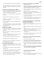
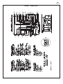
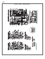
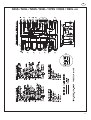
1
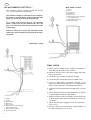
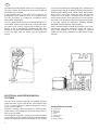
ICE-CUBE MACHINES
N25S / N25L / N35S
N45S / N45L / N50BI
N55S / N55L / N70S
N90S / N90L / N140
Air and water - cooled versions
R 134a
ISO 9001
Cert. N° 0412/2
OUR SYSTEMS COMPLY WITH EEC DIRECTIVE 73/23 - 89/336 CEE
SERVICE MANUAL
Cod. 71503026/0 GB- 01/2006 - Rev. 002
GB
INDEX
GENERAL INFORMATION
• Introduction .........................................................................................................................................................
• Unpacking ad inspection ....................................................................................................................................
pag. 2
“
2
• Locate and levelling ............................................................................................................................................
“
3
• Water supply connections ..................................................................................................................................
“
3
• Electrical connections .........................................................................................................................................
“
4
• Final check .........................................................................................................................................................
“
4
• Operating instructions ........................................................................................................................................
“
5
• Ice - forming cycle ..............................................................................................................................................
“
5
• Electrical and refrigeration systems ...................................................................................................................
“
6
• Machine main parts descriptions ........................................................................................................................
“
7
• Trouble - shooting ...............................................................................................................................................
“
8
INSTALLATION
OPERATION
MAINTENANCE
• Periodical maintenance and cleaning ................................................................................................................
“ 10
• Icemaker cleaning ..............................................................................................................................................
“ 10
• Parts replacement procedures ...........................................................................................................................
“ 10
TECHICAL DATA & WIRING DIAGRAMS
Technical data .......................................................................................................................................................
“ 13
Wiring diagrams ....................................................................................................................................................
“ 22
1
GB
GENERAL INFORMATION
A. INTRODUCTION
This manual provides the specification and the step-bystep procedures for the installation, start-up and operation, maintenance and cleaning for the Icemakers.
The machine cubers are quality designed, engineered and
manufactured.
Their ice making systems are thoroughly tested providing
the utmost in flexibility to fit the needs of a particular user.
This product qualifies for the following listings:
These icemakers have been engineered to our own rigid
sefety and performance standards.
The VDE - SEV - GS seals signifity that it is listed with
them and that it complies with the materials and manufacturing standard of them. These seals also signify that
these icemaker models have been inspectors who reserve
tha right to periodically examine production icemakers at
the factory to assure continued compliance.
NOTE. To retain the safety and performance built into
this icemaker, it is important that installation and maintenance be conducted in the manner outlinde in this manual.
B. UNPACKING AND INSPECTION
1. Call your authorized Distributor or Dealer for proper
installation,.
2. Visually inspect the exterior of the packing and skid.
Any severe damage noted should be reported to the
delivering carrier and a concealed damage claim from
filled in subjetto inspection of the contents with the carrier’s representative present.
3. a) Cut and remove the plastic strip securing the carton
box to the skid.
b) Remove the packing mails securing the carton box
to the skid.
c) Cut open the top of the carton and remove the polystyre protection sheet.
d) Pull out the polystyre posts from the corners and
then remove the carton.
4. Remove the front and the sides panels of the unit and
inspect for any concealed damage. Notify carrier of
your claim for the concealed damage as stated in step
2 above.
5. Remove all internal support packing and masking tape.
2
6. Check that refrigerant lines do not rub against ou touch
other lines or surfaces, and that then fan blades move
freely.
7. Check that the compressor fits snugly onto all its
mounting pads.
8. See data plate on the rear side of the unit and check
that local main voltage corresponds with the voltage
specified on it.
CAUTION. Incorrect voltage supplied to the icemark will void your parts replacement program.
9. Remove tha manufacture’s registation card from the
inside of the User Manual and filling all parts including:
Model and Serial Number taken from the data plate.
Forward the completed self-addressed registration
card the factory.
GB
INSTALLATION
LOCATE AND LEVELLING
This icemaker is designed to be installed in rooms
with temperatures between 10°C and 40°C.
Operating for long period out of these limits will
vaid your warranty program.
Before installing the machine make sure that:
The ambient temperature must not fall bellow 10°C
(50°F) or above 40°C (100°F).
The mains water temperature must not fall below
5°C (40°F) or above 40°C (100°F).
Machine is away from sources of heat and in a sufficiently ventilated area; leave at least 8 inches (20
cms.) between the machine on the back and the
two sides and the wall.
Machine is correctly levelled in both the left to right
and front to rear directions by means of the
adjustable legs.
ted on the water supply machine.
Fix a flexibile palstic pipe (with an inside diameter
of 20 mm. and adequate lenght to reach and open
vented drain) to the waste pipe fitting. In the water
-cooled machine it must also be conected to the
second pipe fitting (that conveys water coming
from the condenser) to the drain.
Level of main drain must be sufficiently below icemaker waste outlets to ensure free flow of waste
water.
The drain recptacle should be an, open, trapped or
vented construction (see skech).
N.B. Make sure that water connection are made
before elettrical connections.
ELECTRICAL CONNECTIONS
Connect machine to water supply first and then to
eletricity supply.
WATER SUPPLY CONNECTIONS
Connect the machine to the eletricity supply after
having checked that the voltage corresponds to
that on the plate on the rear panel of the machine.
The mains water pressure must not fall below 1
atm. (14 Psi) or above 5 atms. (70 Psi). If pressure
is above 5 atms. a pressure regulator shoult be fit-
Connect the machine to the eletricity supply after
having checked that the voltage corresponds to
that on the plate on the rear panel of the machine.
WARNING This icemaker is not designed for outdoor installation and will not function in ambient temperatures
below 10°C (50°F) or above 40°C (100°C).
This icemaker will malfunction with water temperatures below 5°C (40°F) or above 40°C (100°C).
3
GB
Mod. N25W ÷ N140W
ALLACCIAMENTO ELETTRICO....
1)
2)
3)
4)
5)
6)
Switch
Socker
Electrical plug
Water iniet
Suht off valve
Water autlet from the condenser:
water cooled version
7) Water autlet from the bin
8) Open vented water
The maximum voltage variation should not exceed
10% of that stated on the rating plate.
The machine should be connected to an independet fused or suitable power supply protected with
earth. See rating plate for load requirements.
Fix a solid earth ground plug to the electrical
power supply wire of the machine. Be sure the
plug is in conformity with the local electrical code
requirement.
Check by means of a tester the continuity of the
earth mass from the panels to the plug earth terminal board.
Mod. N25S ÷ N140
FINAL CHECK
a) Check that the supply means voltage corresponds to
that stated on the plate of the machine.
b) Open the shut-off valve of the water supply and check
there are no leaks.
c) Check that the icemaker is properly levelled.
d) Check that the storage bin has been wiped clean.
e) Give the “Operationg instructions” manual to the
owner/user and recommend him on the importance to
observe the instructions and period maintenance.
f) Properly fill in the certification card and mail it to Caste
Mac.
g) Check all refrigerant lines and conduit lines or panels
to guard against vibrations and rubbing.
1)
2)
3)
4)
5)
6)
Swicth
Socker
Electrical plug
Water iniet
Shut of valve
Water autlet from the condenser:
water cooled version
7) Water autlet from the bin
8) Open vented water
4
h) Make sure that the unit is installed in a room where the
ambient temperature doesn’t fall below 10°C even winter months.
i) Check that the water supply pressure is of minimum 1
atm (14 Psi).
l) Give the owner the name and the complet address of
the authorized Service in his area.
GB
OPERATION
OPERATING INSTRUCTIONS
Check that the shut-off valve of the water supply is
open, then plug in the machine and swich on the electrical supply; the unit is now ready for automatic operation.
according to the altitude being them different for any thermostat, we suggest regulation by checking if the ice cube
in contact with the thermostat bulb stop the ice-maker not
later than 1 minute.
B) Check that water reaches the pan, that float stops
water inlet before overflow and that there are no water
leaks.
The normal water level inside the pan must not exceed
5 - 10 mm. of its upper part.
The water level can be regulated rotating the
microswitch in the slit of the ralative support, after having removed the fixing screws “1” (see sketch).
This operation must be done after having disconnected the electricity supply.
ICE-FORMING CYCLE
Check that there is no abnormal vibrations due to loose
bolts and screws.
Observe safety practice, disconnect machine from
electricity supply before rectifying water leaks or tightening screws and bolts.
E) Check an ice production cycle ensuring that the cubes
are conveyed into the storage bin.
F) Check the thermostat by putting a cube in contact with
the thermostat bulb inside the storage bin; it must stop
in 1 Minute and it will automatically resume (in a time a
little bit higher) after having removed it.
ATTENTION
In the event the icemaker is installed with altitude higher
than 500 m. from sea level, it is required a different thermostat calibration, as due to barometric pressure
decrease, it is less sensitive and therefore the icemaker
continues to operate even if the storage bin is full.
Access to the thermostat is gained by removing the top of
the wiring case; tighten clockwise the regulating scew
(see sketch). As it is not possible to quantify the turns
The ice cubes form around the fingers of the evaporator,
inside of a pan filled with water which is continuosly
moved by revolving paddies.
The water level is kept constant by a float connected to a
microswitch that controls a water inlet electrovalve.
Dimensions of cubes can be regulated by operating on the
microswitch inclination that controls the water level inside
the pan.
When the ice cubes have reached the required dimensions they get in contact with the revolving paddles that
swings the relative paddle motor which operates a
microswitch that by means of a relay it causes simultaneously:
– Delivery of hot gas to the evaporator by the opening of
an electrovalve, with the consequent fall of cubes from
the evaporator.
– The tilting of the water pan controlled by a lever of the
harvest motor.
The formed cubes fall on a slanting grid inside the pan and
are conveyed in to the storage bin underneath.
The remaining water, collected in a pan placed on one
side of the bin, is then conveyed to the drain.
5
GB
The tilting pan automatically returns to its horizontal position after a minute about and then it fills of water until the
selected level is reached.
In the meantime the hot gas valve il closes and the ice
formingcycle starts again; the time of a complete cycle
can vary from about 15’ to about 25’ according to water
and ambient temperature.
The ice quantity inside the bin is controlled through a termostat bulb fixed on one inside of the storage bin, when
the cubes of ice come in contact with the bulb, the production of ice is automatically discontinued. Only after
enough ice has been removed from the storage bin so as
to free the bulb from the cubes, will the production
resume.
cycle and stops during the defrosting cycle, therefore the
head pressure change on different ambient temperatures.
While on N35S, N55S, N55L, N50BI, N70S, N90S, N90L,
N140 there is a pressure switch that starts and stops the
electric fan so to keep the head pressure constant. On
water-cooled versions the head pressure is kept constant
by means of an automatic valve that regulates the quantity of water cooling the condenser. (N45SW, N55SW,
M50BIW, N70SW, N90SW, 140W models)
On the smallest models instead, the head pressure is kept
constant by a pressure switch that opens and closes a
water inlet solenoid valve which supplies a metered
amdint of water to the condenser in order to limit its temperature.
ELECTRICAL AND REFRIGERATION
SYSTEMS
The “N” series machines operate on standard electrical
supply 220 volts, 50 Hz, single phase. (The tolerance limit
is ± 6 % of the rated base). Special voltages are eventually on specific request.
Therefore, almways check nameplate for electrical information before proceeding with electrical wiring connections to the ice-cubers.
The rifregerant expansion system on the cube machines
is the capillary. On N25S-N25L model the condensing unit
electric fan operates continuously during the ice forming
6
REFRIGERATING SYSTEM
A)
B)
C)
D)
F)
G)
H)
Compressor
Eletric fan
Condenser
Drier
Hot gas valve
Evaporator
Heat exchanger
GB
MACHINE MAIN PARTS DESCRIPTION
L. FAN MOTOR (Air cooled version)
The fan motor, operates during the freezing cycle to draw
B. BIN THERMOSTAT
The bin thermostat, which has its sensing bulb downward
into the storage bin, shuts-OFF automatically the icemaker when the ice storage bin is filled and ice contacts its
bulb.
Lighting of the proper led paints out that the storage bin is
full.
cooling air through the condenser fins so to keep the condensing pressure between the 9/7 bars values.
COOLING WATER INLET SOLENOID VALVE
(N25SW, N35SW)
A second water inlet solenoid valve, operating through an
automatic hi-pressure control, is used on water cooled
versions to supply water to the condenser.
HI PRESSURE CONTROL
(N35S, N55S, N55L, N50BI, N70S, N90S, N90L, N140)
On water cooled ice makers it functions to mainlain the
head pressure within the present values of 8 and 10 bars,
by intermittently activating the water inlet valve to the condenser (in the water cooled models).
On air cooled ice-makers it keeps the head pressure within 2 preset values (8/10 bar) by starting the electric fan of
the condensing unit.
HI TEMPERATURE SAFETY THERMOSTAT
(All water cooled model)
Fastened directly onto the rifregerant liquid line and electrically connected upstream all other controls, this safety
thermostat shut-off the icemakers when senses that the
temperature at the liquid line has rised to the limit of 65°C.
When activated it supplies a metered amount of water to
the condenser in order to limit its temperature and the
refriferant operating high pressure.
N. WATER REGULATING VALVE
(N45SW, N55SW, N50BIW, N70SW, N90SW, N140W)
This valve controls the head pressure in the refrigerant
system by regulating the flow of water going to the condenser.
As pressure increases, the water regulating valve opens
to increases, the water regulating valve opens to increase
the flow of cooling water.
O. COMPRESSOR
FEEDING WATER INLET SOLENOID VALVE
The water inlet solenoid valve is activated only at the end
of the defrosting cycle. When energized it allows a
metered amant of incoming water to flow into the tilting
pan untill the float closes the inlet circuit.
The hermetic compressor is the heart of the refrigerant
system and it is used to circulate and retrieve the refrigerant throughout the entire system. It compresses the low
pressure refrigerant vapor causing its temeprature to rise
and become high pressure hot vapor which is then
released through the disharge valve.
I. THE HOT GAS SOLENOID VALVE
The hot gas solenoid valve consists basically in two parts:
the valve body and the valve coil.
Located on the hot gas line. During the defrost cycle the
hot gas valve coil is activated so to attract the hot gas discharged from compressor to flow directly into the evaporator serpentine to defrost the formed ice cubes.
MAXIMUM PRESSURE SWITCH
(N45SW, N55SW, N50BIW, N70SW, N90SW, N140W)
Fastened directly on to the refrigerant liquid line and electrically connected upstream all other controls, it shut off
the ice-maker when senses that the head pressure reaches 15 bars.
7
GB
TROUBLE - SHOOTING
SYMPTOM
POSSIBLE CAUSE
CORRECTION
Unit will not run
a) Electricity supply disconnected.
Check the electricity supply; replace fuse if
necessary and ckeck for cause.
b) Loose electrical connection.
Check wiring.
c) Damaged storage bin thermostat.
Replace thermostat.
a) Loss or undercharge of refrigerant circuit
Check for leaks, repair, evacuate all the gas
and recharge with R134A by weight (see
nameplate).
b) Water continuously entering into
evaporator chamber.
Check float ball, float ball microswich and
water inlet valve. Replace, if necessary, the
defective components.
c) Moisture in the regrigerant system.
Remove refrigerant charge, raplace drier,
evacuate first, and then recharge.
a) Under-charge of gas.
Check for leak, repair, evacuate all the gas
and recharge.
b) Dirty condenser.
Clean condenser with a non-metal brush or
with a vacuum cleaner.
c) Damaged fan.
Repair and replace fan.
d) Exceedingly warm ambient with low
ventilation.
Move unit to proper location.
e) Partial restriction in drier.
Replace drier, evacuate and recharge.
f) High water level in the reservoir and water
overflows.
Adjust level of float ball microswitch assy.
g) Scale deposit on evaporator.
Polish evaporator.
h) Partial restriction in the capillary tube.
Remove refrigerant charge, evacuate first
and the recharge.
Fan doesnʼt run even if
the delivery pressure
is over 10 atms
Detective pressure switch.
Remplace.
Compressor cycles
intermittently
a) Low voltage.
Check electrity supply.
b) Dirty condenser.
Clean.
Machine runs but
makes no ice
Low ice production
8
GB
DIFETTI
CAUSA
RIMEDI SUGGERITI
c) Air circulation blocked.
Move unit to cooler location.
d) Non-condensable gases in system.
Purge-off.
e) Detective compressor electrical
components.
Replace electrical components.
f) Mechanical or electrical failure inner
compressor.
Remplace compressor.
Icecubes are too low
a) Water level in the pan is too low.
Adjust level by raising the float ball
micro-swicht assy.
Icecubes are too long
a) Water level in the pan is too high.
Adjust level by lowering the float ball microswicht assy.
b) Water solenoid valve is not water-tight.
Check the valve in order to remove eventual
obstructions, or replace defective parts.
a) Incorrect position of revolving paddles.
Center the paddles in accordance with the
evaporator components.
b) Unit is not properly levelled.
Check the machine level by working with the
adjustable feet.
a) Impure water.
Clean the water inlet filter.
b) Calcareous water.
Install a water softener.
a) Detective water seal.
Check and repair.
Unproper shape and/or
irregular dimension of
cubes
Deposits in the pan
Water leaks
9
GB
MAINTENANCE
PERIODICAL
MAINTENANCE AND CLEANING
N.B.: Cleaning and maintenance especially will vary,
depending upon ambient and use conditions.
In particular affect: hard water, ice volume produced and
location requirements.
The following maintenance procedures should be scheduled once per year al least from the local service Agency.
Be sure the electrical power supply of the machine is
OFF, before starting any maintenance and cleaning
procedure.
a) Close the water supply, shut-off valve, disconect the
water inlet pipe and remove the strainer from its seat in
the water inlet elettrovalve withdrawing it bay means of
pilers. Clean the strainer under running water and
reassemble.
b) Check that the ice maker cabinet is levelled in side-toside and front-to-rear directions.
c) Check paddle shaft motor and harvest motor operation.
e) Add hot water to the ice storage bin and thoroughly
wash and rinse all surfaces within the bin.
f) Clean and sanitize the ice storage bin frequently.
PARTS REPLACEMENT PROCEDURES
A) ADJUSTABLE LEGS FOR N55S÷N90L MODELS
Using the couplings and adjustable feet supplied and
screwing them on the base nipples the icemaker can be
placed at 9,5 cm. abt. from ground level.
Extended feet are available on request to adjust the icemaker at 16 cm. about from ground level. A kit of extension feet can be supplied on request also for the N35S
model.
The adjustment should be performed during initial installation of the cabinet and any time the cabinet is moved
from the original location to another site.
N.B.: (WARNING) Be sure the electrical power supply
and the water supply are OFF, before starting any
removal and replacement procedures, as a precaution
to prevent possible personal injury or damage to
equipment.
d) If you think it opportune, check by means of a gauges
the delivery pressure and the evaporator temperature.
e) Clean the air-cooled condenser using a nonmetal
brush or a vacuum cleaner.
B) COMPRESSOR REPLACEMENT
a) Remove the rear panel on the N25S-N25L model and
the rear panel grid on N35S model
f) Check that fan blades move freely and are not touching any sourfaces.
On N45S÷N140 models remove the rear panel grid
and the side panels.
g) Check for refrigerant leaks.
h) Check for water leaks. Pour water down bin drain to be
sure that drain line is open and clear.
i) Check operation of the bin thermostat.
Remove the cover and disconnect the electrical leads
from the compressor junction box.
Bleed off or blow the refrigerant charge through the
valve.
Unsolder and disconnect both the suction line and the
discharge line (from the compressor).
ICEMAKER CLEANING
a) Remove the top panel.
b) Remove all ice from the storage bin.
c) Close the water supply shut-off valve.
d) Fill tilting pan with a solution of water and citric acid
(200-400 grs. of citric acid in one litre of water) and by
means of a brush clean the inside of the tilting pan and
the evaporator fingers. Start the icemaker to tilt the
pan, rinse with clean water in abudance and repeat
cleaning three times.
10
Remove compressor mounting bolts and the compressor from the unit base.
Always install a replacement drier, anytime the sealed
refrigeration system is open. Do not replace the drier
until all other repairs or replacements have been completed.
To install the replacement compressor follow previous
steps in reverse.
Thoroughly evacuate the system to remove moisture
GB
and non-condensables after compressor replacement.
F) EVAPORATOR ASSEMBLY REPLACEMENT
a. Remove the top cover.
Before proceeding with the refrigerant charge check
nameplate for specific refrigeration charge for individual cuber.
b. Remove six screws securing the paddle shaft supports
(two) and the paddle motor support; then remove the
paddle motor/paddle shaft/supports assembly.
C) AIR COOLED CONDENSER REPLACEMENT
Remove the rear panel grid on N25S, N25L and N35S
models. On N45S÷N140 and upper models remove
the front panel grid and the side panels.
Remove the screws which attach the condenser to the
unit base.
Bleed off or blow the refrigerant from the system.
c. Remove the bolts securing the evaporator supports
(two) to the cabinet.
d. Sideways remove the evaporator supports.
e. Unsolder the capillary tube, the hot gas solenoid valve
tube and the suction line.
f. To install the replacement evaporator assembly follow
previous steps in reverse.
g. Install the replacement drier; thoroughly evacuate the
system and proceed with the refrigerant charge.
Unsolder the refrigerant lines from condenser and
remove it from the unit.
Install the replacement condenser following previous
steps in reverse.
Thoroughly evacuate the system to remove moisture
and non condensables; then proceed with the charge
of FREON R134a.
D) DRIER REPLACEMENT
Remove the rear panel grid on N25S, N25L and N35S
Models. On N45S÷N140 models remove the side
panel grids.
Bleed off or blow the refrigerant charge through the
Henrytype valve.
Unsolder the capillary tube from one end of the drier
and the refrigerant line from the other end.
To install a replacement drier remove factory seals.
Thoroughly evacuate the refrigerant system.
G) WATER RESERVOIR/TILTING LEVER/SUPPORT
ASSEMBLY REPLACEMENT
a. Remove screws and top cover.
b. Remove the gear motor/paddle shaft/support assembly.
c. Remove the screws securing the evaporator supports
(two).
d. Sideways remove one evaporator support support as
well as one reservoir gudgeon support.
e. Slightly lift the evaporator and remove the water reservoir assembly.
f. To install the replacement water reservoir assembly
follow previous steps in reserve.
H) WATER INLET ELECTROVALVE REPLACEMENT
a. Remove the rear panel.
b. Check that water supply is closed.
Charge the system with refrigerant by weight (see
nameplate) and check for leaks.
c. Disconnect the water supply connection pipe from the
valve and that of the electrovalve from the reservoir.
E) FAN MOTOR REPLACEMENT
Remove the rear panel grid on N25S, N25L and N35S
models. On N45S÷N140 models remove the side
panel grids.
d. Break contact from the electrovalve and remove the
screws (two) securing the electrovalve to the relevant
frame.
Trace the electric wire leads of fan motor and disconnect the same.
Remove the bolts securing the fan motor assembly to
the cabinet base and the remove the assembly.
Install the replacement fan motor following previous
steps in reverse anc check that the fan blade do not
touch any sourface and move freely.
e. To install the replacement electrovalve follow previous
steps in reverse; before installing the water supply pipe
check that the gasket is not defective.
I. PADDLE MOTOR REPLACEMENT
a. Remove the top cover.
b. Remove six screws securing the paddle shaft supports
(two) and the paddle motor support.
11
GB
c. Trace the electric wire leads of paddle motor and disconnect the same; then remove the paddle shaft motor
assy.
d. Remove the paddle shaft assy from the paddle motor
gudgeon (or guide pin).
e. To install the replacement paddle motor follow previous
steps in reverse.
L) HARVEST MOTOR REPLACEMENT
a. Remove the top cover.
f. Install the replacement harvest motor on the support
and apply the cam; make a Ø 3 mm hole on the motor
shaft and to do it take as a guide the hole already existing on the cam.
g. To install the replacement harvest motor assy follow
previous steps in reverse.
M) THERMOSTAT OR RELAY REPLACEMENT
a. Remove the rear panel on N25S model.
On N35S÷N140 models remove the top cover.
b. Remove the terminal box cover.
b. Remove the screws securing the harvest motor to the
cabinet base.
c. Remove the screws securing the terminal box to the
cabinet.
c. Remove the seeger from the cam pin.
d. Slightly lift the terminal box and remove the screws
securing the thermostat or the Relay to the box same.
d. Trace the electric wire leads of harvest motor and disconnect the same; then remove the harvest
motor/cam/support assembly.
e. Remove the lock pin securing the cam to the motor
shaft and the screws joining the harvest notor to the
relative support.
12
e. Remove the Relay or the Thermostat; in this last case
remove the supports securing the bulb in the storage
bin first, the lift it from the storage bin through the proper slit.
f. To install the replacement thermostat or relay follow
previous steps in reverse.
134A
134A
134A
134A
134A
134A
134A
134A
134A
134A
134A
134A
134A
134A
134A
134A
134A
134A
134A
134A
134A
134A
134A
134A
N21S A
N21S W
N25S A
N25S W
N25L A
N25L W
N35S A
N35S W
N45S A
N45S W
N45L A
N45L W
N55S A
N55S W
N55L A
N55L W
N50BI A
N50BI W
N70S A
N70S W
N90S A
N90S W
N140 A
N140 W
ELECTROLUX GL60TB
220/50HZ
ELECTROLUX GL60TB
220/50HZ
ELECTROLUX GL45TB
220/50HZ
ELECTROLUX GL45TB
220/50HZ
ELECTROLUX GL45TB
220/50HZ
ELECTROLUX GL45TB
220/50HZ
ELECTROLUX GL90TB
220/50HZ
ELECTROLUX GL90TB
220/50HZ
ELECTROLUX GL90TB
220/50HZ
ELECTROLUX GL90TB
220/50HZ
ELECTROLUX GL90TB
220/50HZ
ELECTROLUX GL90TB
220/50HZ
UNITE' HERMETIQUE
CAE4448Y 220/50HZ
UNITE' HERMETIQUE
CAE4448Y 220/50HZ
UNITE' HERMETIQUE
CAE4448Y 220/50HZ
UNITE' HERMETIQUE
CAE4448Y 220/50HZ
UNITE' HERMETIQUE
GP14TB
UNITE' HERMETIQUE
GP14TB
UNITE' HERMETIQUE
CAE4448Y 220/50HZ
UNITE' HERMETIQUE
CAE4448Y 220/50HZ
UNITE' HERMETIQUE
CAJ4461Y 220/50HZ
UNITE' HERMETIQUE
CAJ4461Y 220/50HZ
UNITE' HERMETIQUE
CAJ4511Y 220/50HZ
UNITE' HERMETIQUE
CAJ4511Y 220/50HZ
TYPE COMPRESSOR
2,5A
2,4A
3,6A
220
220
220
3,7A
3.6A
340
340
5,2A
4,8A
640
640
4,2A
4,7A
410
410
3,6A
360
3,6A
3,6A
360
360
3,6A
3,6A
3,6A
3,6A
360
360
360
220
2,4A
2,7A
220
220
1,4A
140
1,4A
1,4A
140
140
1,6A
2A
160
140
2A
160
4A
4,5A
3,8A
4A
3A
3,3A
3A
3,3A
2,8A
3A
2,8A
3A
2A
2,1A
2A
2,1A
2.0A
2,1A
1,2A
1,2A
1,2A
1,4A
1,8A
1,8A
COMPRESSOR
MAX. MEDIUM
POWER
AMPER AMPERE
IN WATT *
-10
9
9.5
9
-5
-8
11
9
-6
-3
11
9
9
11
-4
-8
-5
-8
9
11
-8
-6
9
9
9
9
9
8-10
10
8-10
8-10
8-10
9
9
9
-6
-6
-4
-6
-4
-4
-2
0
0
0
-2
-8
-3,3
-18
-17
-14
-13
-12
-12
-16
-16
-18
-16
-18
-16
-14
-13
-14
-13
-16
-15
-13
-13
-13
-13
-17
-17
22.5
23.5
15.5
16
12.2
12.5
13.5
14.5
11.5
12
11.5
12
7.8
8.0
7.8
8.0
8.2
8.6
5.3
5.3
5.3
5.8
7,5
7,5
90/17g
90/17g
60/17g
60/17g
60/17g
60/17g
35/17g
35/17g
35/17g
35/17g
35/17g
35/17g
35/17g
35/17g
35/17g
35/17g
20/17g
20/17g
15/17g
15/17g
15/17g
15/17g
15/19G
15/19G
84
19
48
11
40
9
37
7
37
7
37
7
30
5,5
30
5,5
22
4,7
15
2,8
15
2,8
21
6
** EXPRESSED IN LITRES FOR HOUR WITH WATER TEMPERATURE OF 15°C AND AMBIENT TEMPERATURE OF 21°C
9
11.5
9
15
9
13.5
9
13
9
12.5
9
12.5
9
12
9
12
10
14
8-10
8-10
8-10
11
9,5
11,5
CUBES FOR
CONDENSING EVAPORATION CONDENSING EVAPORATION
ELECTR.
WATER
CYCLES AND
PRESSURE TEMPERATUPRESSURE TEMPERATURE
CONSUMPTION
CONSUMPTION
WEIGHT SINGLE
STARTING RE STARTING END CYCLE
END CYCLE
ON 24 HRS/KW
**
CUBES IN GRAM
CYCLE (BARS) CYCLE (°C)
(BARS)
(°C)
N
*ABSORVED POWER AT EVAPORATION TEMPERATURE OF -15°C
GAS
MACHINE
GB
MEDIUM AND MAXIMUM ABSORBITION ON THE "N" LINE MACHINES AT 32¡C ROOM TEMPERATURE
CONDENSING PRESSURE AND EVAPORATOR TEMPERATURE AT STARTING AND END CYCLE AT 32¡C ROOM TEMPERATURE
TECHNICAL DATA FOR ICE CUBES MACHINE
GB
WIRING DIAGRAMS
N25S AIR
14
GB
N25L - N35S AIR
15
GB
N25S - N25L - N35S WATER
16
GB
N45S / N45L / N55S / N55L / N70S / N90S / N90L AIR
17
GB
N45S / N45L / N55S / N55L AIR
18
GB
N50 B.I.
AIR
19
GB
N50 B.I.
20
WATER
GB
N70S / N90S / N90L WATER
21
Via del Lavoro, 9 C.P. 172
I - 31033 Castelfranco Veneto (TV) Italy
Tel. (0423) 738452 - Fax (0423) 722811
E-mail: [email protected]
Web-site: www.castelmac.it
Cod. 71503026/0 GB- 01/2006 - Rev. 002