1
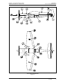
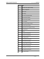
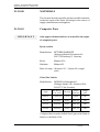
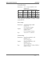
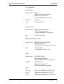
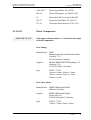
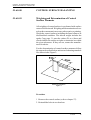
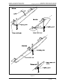
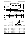
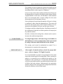
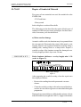
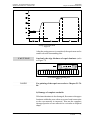
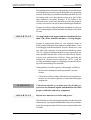
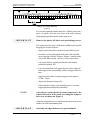
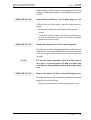
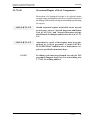
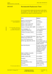
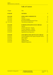
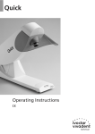
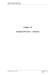
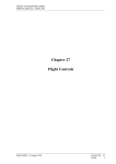
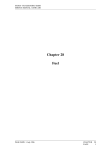
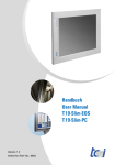
EXTRA - FLUGZEUGBAU GmbH
SERVICE MANUAL EXTRA 300
Chapter 51
Standard Practices and Structures - General
PAGE DATE: 31. January 1995
CHAPTER
PAGE
51
1
EXTRA - FLUGZEUGBAU GmbH
SERVICE MANUAL EXTRA 300
TABLE OF CONTENTS
Chapter
Title
51-00-00
51-00-01
GENERAL
Access Panel Identification
51-10-00
51-10-01
51-10-02
INVESTIGATION
Damage Classification
Repair Criteria and Limits
51-30-00
51-30-01
51-30-02
51-30-03
MATERIALS
Composite Parts
Metal Components
Aluminium Components
51-60-00
51-60-01
CONTROL SURFACE BALANCING
Weighing and Determination of
Control Surface Moments
................................................................................................................
.........................................................................
............................................................................................
.....................................................................................
............................................................................
51-70-02
51-70-03
51-70-04
51-70-05
51-70-06
51-70-07
PAGE DATE: 31. January 1995
6
6
7
8
8
11
12
.........................................................................................................
.....................................................................................................
............................................................................................
............................................................................
..................................
.........................................................................
51-70-00
51-70-01
3
3
REPAIRS
Repair of Reinforced Glass and
Carbon Fibre Components
Repair of Sandwich Material
Repair of Laminates
Repair of Spars
Structural Repair of Steel Components
Painting of Composite Parts
Aluminium and Steel Components Refinishing
................................................................................................................
......................................................................
.................................................................
.......................................................................................
....................................................................................................
........................................
...................................................................
...................
CHAPTER
PAGE
14
14
18
18
20
25
29
30
31
32
51
2
EXTRA - FLUGZEUGBAU GmbH
SERVICE MANUAL EXTRA 300
51-00-00
GENERAL
51-00-01
Access Panel Identification
For the Extra 300 all removable covers and fairings are
defined as access panels (refer to Figure 1 and the adjacent
chart). If maintenance or repair is not restricted to a small
area it is advisable to remove all access panels before
beginning work or checks.
NOTE
Access panels partly overlap. Remove the front panels
first.
All panels are screwed. For the removal/installation of the
wing tip panels refer to Chapter 57.
Prior to unscrewing of the air inlet screen remove bottom
half of the engine cowling not to lose the attachment stopnuts
and washers.
PAGE DATE: 31. January 1995
CHAPTER
PAGE
51
3
EXTRA - FLUGZEUGBAU GmbH
SERVICE MANUAL EXTRA 300
GENERAL
Access Panel Identification
Access Panel Identification
Figure 1
PAGE DATE: 31. January 1995
CHAPTER
PAGE
51
4
EXTRA - FLUGZEUGBAU GmbH
SERVICE MANUAL EXTRA 300
GENERAL
Access Panel Identification
Position Item
PAGE DATE: 31. January 1995
1
Top half of the engine cowling
2
Tank covering sheet
3
Turtle deck
4
Tail fairing
5
Tail cone access panel (RH)
6
Tail side skin (LH/RH)
7
Rear side skin (LH/RH)
8
Cuff (LH/RH)
9
Wheel speed fairing (LH/RH)
10
Front side skin (LH/RH)
11
Bottom half of the enginge cowling
12
Air inlet screen
13
Spinner
14
1. bottom covering sheet
15
2. bottom covering sheet
16
LH wing tip panel
17
LH outbourd access panel
18
LH inboard access panel
19
3. bottom LEXAN-window
20
4. bottom covering sheet
21
RH inboard access panel
22
RH outboard access panel
23
RH wing tip panel
CHAPTER
PAGE
51
5
EXTRA - FLUGZEUGBAU GmbH
SERVICE MANUAL EXTRA 300
51-10-00
INVESTIGATION
51-10-01
Damage Classification
WARNING
All damage of composite parts must first be classified
by qualified personnel. In case of doubt with regard to
the classification of damage, if a clear definition of the
extent of damage is not possible, or if a repair of damage inspite of the valid manufacturer documentation is
doubtful, contact EXTRA-FLUGZEUGBAU GmbH.
WARNING
Only the Damages Classes 2, 3 and 4 may be repaired
by qualified personnel. In case of Damage Class 1 it
has to be contacted EXTRA-FLUGZEUGBAU GmbH.
According to the Luftfahrt-Bundesamt (Federal German
Aviation Authority) four damage classes are defined:
Damage Class 1:
Large scale destruction requiring a partial reconstruction of
the component or large scale repair. Each destruction over
300 mm diameter and each damage of a spar is a large scale
destruction. EXTRA-FLUGZEUGBAU GmbH has to be
contacted prior to repair.
Damage Class 2:
Damage to primary structures and to secondary structures to
the following extent: Holes and fractures extending through
a sandwich component and a scale under 300 mm diameter.
Damage Class 3:
Damage to primary structures and to secondary structures to
the following extent: Small holes or fractures in the external
covering layers, if not accompanied by damage to supporting
layers or internal covering layers.
PAGE DATE: 31. January 1995
CHAPTER
PAGE
51
6
EXTRA - FLUGZEUGBAU GmbH
SERVICE MANUAL EXTRA 300
Damage Class 4:
INVESTIGATION
Damage Classification
Erosion, scratches or nicks not accompanied by fractures or
breakages. Damage to fairings belong to this class.
51-10-02
Repair Criteria and Limits
IMPORTANT
ll damage of composite parts must first be classified
prior to repair. Refer to Chapter "51-10-01 Damage
Classification".
IMPORTANT
Only the Damages Classes 2, 3 and 4 may be repaired
by qualified personnel. In case of Damage Class 1 it
has to be contacted EXTRA-FLUGZEUGBAU GmbH.
The decision whether to repair or replace a major unit of
structure will be influenced by factors such as time and labor
available, and by comparison of labor costs with the price of
replacement assemblies. Past experience indicates that
replacement, in many cases, is less costly than major repair.
Certainly, when the aircraft must be restored to its airworthy
condition within limited time, replacement is preferable.
PAGE DATE: 31. January 1995
CHAPTER
PAGE
51
7
EXTRA - FLUGZEUGBAU GmbH
SERVICE MANUAL EXTRA 300
51-30-00
MATERIALS
This Section describes metallic and non-metallic materials
used in the repair of the Extra 300 and gives the sources of
supply (manufacturers and supplier).
51-30-01
IMPORTANT
Composite Parts
Only approved materials have to be used for the repair
of composite parts.
Epoxy-system
Manufacturer: RÜTGERS, BAKELITE
Aktiengesellschaft,Varzinerstr. 49,
D-47138 Duisburg 12, Germany
Resin:
Hardener:
Rütapox L20
Rütapox SL
Ratio of comp.: 100 parts L20 / 34 parts SL (weight
ratio)
Glass fibre fabrics
Manufacturer: INTERGLAS, Interglas AG
Söflinger Straße 246, Postfach 3820,
D-89077 Ulm, Germany
Style
90070
92110
92125
92140
WLB-No.*
US-style
LN 9169
weave
patterns
weigh
g/m²
1610
plain
80
none
twill 2/2
163
8455160
none
twill 2/2
280
8455160
none
twill 2/2
390
8.4505.60
8454860
*All glass fabric is made of alkali-free E glass with Volan-A
finish or with finish I 550.
PAGE DATE: 31. January 1995
CHAPTER
PAGE
51
8
EXTRA - FLUGZEUGBAU GmbH
SERVICE MANUAL EXTRA 300
MATERIALS
Composite Parts
Carbon fibre fabrics
Manufacturer: CCC, C. Cramer GmbH & Co. KG
Postfach 209,
D-48619 Heek-Nienborg, Germany
Style CCC
447
452
459
WLB-No.*
weave
US-style
DIN 65147
patterns
8,3507;80
weight
g/m²
8,3520;80
none
plain
160
none
twill 2/2
204
-
none
cross-twil
220
*WLB: Werkstoff Leistungsblatt, according to German
standard DIN-WL
Glass rovings:
Manufacturer: GEVETEX Textilglas-GmbH
Postfach 426,
D-5100 Aachen, Germany
Supplier:
Type:
Lange & Ritter GmbH
Postfach 100321,
D-7016 Gerlingen, Germany
Vetrotex EC14 - 2400-P185
Carbon rovings:
Manufacturer: Tenax Fibers GmbH & Co. KG
Kasinostr. 19-21
D-42103 Wuppertal
Supplier:
Type:
PAGE DATE: 31. January 1995
Tenax Fibers GmbH & Co. KG
Kasinostr. 19-21
D-42103 Wuppertal
TENAX J HTA 5131 1600tex f24000 t 0
(WLB: 8.3614.85)
CHAPTER
PAGE
51
9
EXTRA - FLUGZEUGBAU GmbH
SERVICE MANUAL EXTRA 300
MATERIALS
Composite Parts
Core material
a) PVC Foam:
Manufacturer: DIAB
Divincell International Gmbh
Max-von-Laue-Straße 7
D-30966 Hemmingen, Germany
Supplier:
Type:
see above
Divinycell HT 50
b) Honeycomb:
Manufacturer: EURO COMPOSITES S.A:
B.P.95, Zone Industrielle,
L-6401 Echternach / Luxembourg
Type:
ECA-I-R 4.8-29-R
Filler material for resin:
Manufacturer: EBERHARD Chemie GmbH
Olpener Straße 405,
D-51109 Köln 91 (Merheim), Germany
Type:
- Cotton flakes
- Microballoons BJO - 0930
Paint:
Manufacturer: GLASURIT GmbH
Max-Winkelmannstr. 80,
D-48165 Münster/Hiltrup, Germany
Supplier:
Type:
285-100
929-73
352-91
PAGE DATE: 31. January 1995
WESSELS AG
Pagenstecherstraße 121,
D-49090 Osnabrück, Germany
Glassodur-Rapidfüller AC 85-0100
Glassodur-MS-Härter SC 29-0173
Glassodur-Einstellzusatz SV 41-0391
CHAPTER
PAGE
51
10
EXTRA - FLUGZEUGBAU GmbH
SERVICE MANUAL EXTRA 300
1006-202/3
Glassit Härterpaste, rot SB 48-3360
929-73
Glassodur-MS-Härter SC 29-0173
352-91
IMPORTANT
Glassit Spritzfüller SP 60-7023
948-36
21-
51-30-02
MATERIALS
Composite Part Materials
Glassodur-PUR-Acryl-Lack AD/AE 2
Glassodur-Einstellzusatz SV 41-0391
Metal Components
Only approved materials have to be used for the repair
of metal components.
Steel tubing:
Manufacturer: MHP
Mannesmann Hoesch Präzisrohr GmbH
Postfach 1713,
D-59061 Hamm, Germany
Supplier:
Type:
HEINE+BEISSWENGER Stiftung + CO
Postfach 1510,
D-70705 Fellbach, Germany
WLB 1.7734.4
18mm x 1.0mm, 20mm x 1.0mm,
22mm x 1.0mm, 22mm x 1.5mm,
25mm x 1.5mm
Steel sheet metal :
Manufacturer: BÖHLER Edelstahl GmbH
München, Germany
Supplier:
Type:
PAGE DATE: 31. January 1995
BÖHLER Edelstahl GmbH
Hansa Allee 321,
D-40549 Düsseldorf, Germany
WLB 1.7734.4
1.0mm, 1.5mm, 2.0mm, 3.0mm
CHAPTER
PAGE
51
11
EXTRA - FLUGZEUGBAU GmbH
SERVICE MANUAL EXTRA 300
MATERIALS
Metal Components
Paint:
Manufacturer: GLASURITGmbH
Max-Winkelmannstr. 80,
D-48165 Münster / Hiltrup, Germany
Supplier:
Type:
801-1552
Glassofix Grundfüller-EP AC 01-1492
21-
Glassodur-PUR-Acryl-Lack AD/AE 2
352-91
Glassodur-Einstellzusatz SV 41-0391
965-32/2
1929-73
51-30-03
WESSELS AG
Pagenstecherstraße 121,
D-49090 Osnabrück, Germany
Glassofix Härter-EP
SC 65-0322
Glassodur-MS-Härter SC 29-0173
Aluminium Components
Aluminium sheet metal:
Manufacturer: Kaiser Aluminium & Chem. Corp.
Spokane, Washington
Supplier:
Type:
Westdeutscher Metallhandel
Postfach 104245
45141 Essen
WLB 3.1364. T3511 or 2024 T3
0.6mm; 0.8mm; 1.2mm
Control rod tubings:
Manufacturer: Aluminium AG
CH-5737 Menziken
Supplier:
Type:
PAGE DATE: 31. January 1995
Karstens & Knauer GmbH&Co
D-28865 Lilienthal
WLB 3.1354. T3
ø 25x1mm
CHAPTER
PAGE
51
12
EXTRA - FLUGZEUGBAU GmbH
SERVICE MANUAL EXTRA 300
MATERIALS
Aluminium Components
Paint:
Manufacturer: GLASURIT GmbH
Max-Winkelmannstr. 80,
D-48165 Münster / Hiltrup, Germany
Supplier:
Type:
Primer:
283-150
352-228
Lacquer:
WESSELS AG
Pagenstecherstraße 121,
D-49090 Osnabrück, Germany
Glassofix-Grundfüller AB83-1150
Glassofix-Zusatzlösung SC12-0228
21-
Glassodur-PUR-Acryl-Lack AD/AE 2
352-91
Glassodur-Einstellzusatz SV 41-0391
1929-73
Glassodur-MS-Härter SC 29-0173
Aluminium hardware metal (brackets, pedestals,
castings, etc.):
Paint:
Manufacturer: Parker & Anchem, Ambler, PA 19002
Supplier:
Aircraft Spruce
Lacquer:
see above
Chem. coating: Alodine No. 1201 (MIL-C-5541)
PAGE DATE: 31. January 1995
CHAPTER
PAGE
51
13
EXTRA - FLUGZEUGBAU GmbH
SERVICE MANUAL EXTRA 300
51-60-00
CONTROL SURFACE BALANCING
51-60-01
Weighing and Determination of Control
Surface Moments
All weighing of control surfaces is performed with surface
removed from aircraft. Weighing and determination of control surfaces moments is necessary after repairs or painting.
Weigh the control surfaces including the mass balances in
disassembled condition. The aileron weight includes the
spade. Copy page 31, enter the values (W, m, r) there and
check whether the surface weights or moments are within
the given tolerances. If they are not, contact the manufacturer for advice.
For the determination of control surface moments follow
the steps as described below and use two balancing mandrels
like shown in the Figure 2:
Balancing Mandrels
Figure 2
Procedure
1 Remove the control surface (refer to chapter 27).
2 Reinstall the bolts in two brackets.
PAGE DATE: 31. January 1995
CHAPTER
PAGE
51
14
EXTRA - FLUGZEUGBAU GmbH
SERVICE MANUAL EXTRA 300
CONTROL SURFACE BALANCING
Weighing and Determination of Control Surface Moments
3 Put the control surfaces on the balancing mandrels (use
a wire for the trim tab).
4 Weigh by means of a conventional spring balance (kg/gindication) at the given weighing points (Figure 3) and
enter the weight (m) in Figure 4.
5 Measure distance of hinge center line to weighing
point (r) and enter the value in Figure 4.
6 Calculate the control surface moment (M) in Figure 4.
7 Reinstall the control surfaces only if the weight and
moment values fall within the permissible values stated
in Figure 4.
PAGE DATE: 31.
1. June
January
19961995
CHAPTER
PAGE
51
15
EXTRA - FLUGZEUGBAU GmbH
SERVICE MANUAL EXTRA 300
CONTROL SURFACE BALANCING
Weighing and Determination of Control Surface Moments
Determination of Control Surface Moments
Figure 3
PAGE DATE: 31. January 1995
CHAPTER
PAGE
51
16
EXTRA - FLUGZEUGBAU GmbH
SERVICE MANUAL EXTRA 300
CONTROL SURFACE BALANCING
Weighing and Determination of Control Surface Moments
Permissible Weights and Moments
250
Elevator
(incl. mass balance)
200
Rudder
(incl. mass balance)
150
Aileron
(incl. mass balance and spade)
100
50
0
3.5
3
2.5
2
1.5
1
5
5.5
6
Mass (kg)
6.5
7
7.5
Trim tab
70
80
90
Weights
Aileron LH:
(W) . . . . . . . . . . kg
Rudder:
(W) . . . . . . . . . . kg
Trim Tab:
(W) . . . . . . . . . . kg
100
110
Mass (g)
120
130
140
Aileron RH: (W) . . . . . . . . . . kg
Elevator:
Moments
(W) . . . . . . . . . . kg
Aileron LH:
(m:) . . . . . . . kg . 9.81m/s2 . (r:) . . . . . . . cm = (M:) . . . . . . . . . . Ncm
Elevator:
(m:) . . . . . . . kg . 9.81m/s2 . (r:) . . . . . . . cm = (M:) . . . . . . . . . . Ncm
Aileron RH: (m:) . . . . . . . kg . 9.81m/s2 . (r:) . . . . . . . cm = (M:) . . . . . . . . . . Ncm
Rudder:
(m:) . . . . . . . kg . 9.81m/s2 . (r:) . . . . . . . cm = (M:) . . . . . . . . . . Ncm
Trim Tab:
(m:) . . . . . . . kg . 9.81m/s2 . (r:) . . . . . . . cm = (M:) . . . . . . . . . . Ncm
15. January
December
1999
PAGE DATE: 31.
1995
Control Surface Weights and Moments
Figure 4
CHAPTER
PAGE
51
17
EXTRA - FLUGZEUGBAU GmbH
SERVICE MANUAL EXTRA 300
51-70-00
REPAIRS
51-70-01
Repair of Reinforced Glass and Carbon
Fibre Components
IMPORTANT
Repair of composite parts has to be carried out only by
qualified and authorized personnel.
If the aircraft is damaged, proceed as follows. First conduct
a careful visual inspection of the surface and the damaged
area. Frequently, the damage extends to futher components,
sometimes a fracture will continue invisible beneath the
surface.
Perform the repair work with utmost care. The external shell
of the wing and empannage is stressed; a failure of this
bonded structure can lead to an aircraft crash. In order to
eliminate dangerous stress concentrations, avoid changes in
cross-sectional areas.
IMPORTANT
The resin-hardener mixture ratio must be precisely
maintained (+0.5%). Clean cups and tools must be used.
The weight ratio of glass fabric to resin mixture should
be approximately 50:50.
Immediately prior to applying the wet laminate, sand and
vacuum clean the repair area, so that no dirt and dust is
involved which could prevent a secure adhesion.
WARNING
Sanding carbon and glass fibre laminates gives off a fine
dust that may cause skin and/or respiratory irritation
unless suitable skin and resiration protection is used.
WARNING
Carbon-tetracloride or Acetone used for cleaning repair areas are flamable liquids and should be used with
proper ventilation and safety equipment.
IMPORTANT
As with plywood grain, the direction of the various fibres (longitudinal or diagonal) is of great importance
for the stability.
PAGE DATE: 31. January 1995
CHAPTER
PAGE
51
18
EXTRA - FLUGZEUGBAU GmbH
SERVICE MANUAL EXTRA 300
REPAIRS
Repair of Reinforced Glass and Carbon Fibre Components
The number of layers required to restore the stability in the
damaged area can be taken from the layer sequence/placement plan.(Refer to the respective Chapters)
It is necessary to know the number and direction of layers in
the damaged area, in order to be able to replace them with the
original number. In all cases, the thickness of the laminate
has to be measured with a vernier calliper for the exact
determination of the laminate tickness.
One technique to learn about the number of layers is to burn
a small piece taken from the damaged area. The resin will
burn off, leaving the glass and/or carbon fabric to be inspected for the number of layers and the type of fabric.
Creating a scarfed overlap takes time. Sand away as much of
the old material, that the new fabric patches do not project
beyond the contour.
In order to shorten the curing time, a heater can be used to
increase the ambient temperature.
CAUTION
Too high temperature will cause large air bubbles in
the laminate. Local overtemperature can be prevented
by using a foil tent which leads the hot air stream.
The curing cycle must be maintained as stated. Use a
thermometer to monitor the temperature.
IMPORTANT
After repair of control surfaces, check for proper balance ( refer to chapter 27, Flight Controls).
It is recommended to prepare test specimens at the same
time as the actual repair is accomplished. These can then be
subject to a material test to establish the quality of the
laminate in the repaired part. To make this determination
valid, the specimens must be assembled with the same style
of fabric and resin mixture. Subsequently the specimens
must be subject to the curing pressure, temperature and time
identical with those in the actual repair.
PAGE DATE: 31. January 1995
CHAPTER
PAGE
51
19
EXTRA - FLUGZEUGBAU GmbH
SERVICE MANUAL EXTRA 300
51-70-02
REPAIRS
Repair of Sandwich Material
Two types of core materials are used for sandwich on the
EXTRA 300:
- PVC hard foam
- Honeycomb
both with glass or carbon fibre shells
The following section describes the repair of both types of
sandwich. Different processing techniques for these materials, if necessary, are also described.
a) Minor surface damage
Around a visible crack, the laminate may be separated from
the core material. Determine the extent of this area by coin
tapping. Remove the separated laminate carefully using a
sanding disk, sanding block or a sharp knife. Prepare a
scarfed overlap of the laminate around the damaged area.
Overlap lenght per fabric layer min. 20 mm;
IMPORTANT
Ratio (laminate thickness : overlay lenght) min. 1: 50
(refer to Figure 5).
Minor surface damage
Figure 5
After preparing the scarfed overlap, clean the repair area
thoroughly as follows:
- Remove the sanding dust with a pneumatic vacuum
cleaner
- Clean the scarfed overlaps with carbon-tetrachloride or
acetone in case of dirt or grease was introdued during the
preparation.
Damaged core material has to refilled with a mixture of resin
and microballoons (weight ratio 100:15). Apply resin mixture
PAGE DATE: 31. January 1995
CHAPTER
PAGE
51
20
EXTRA - FLUGZEUGBAU GmbH
SERVICE MANUAL EXTRA 300
REPAIRS
Repair of Sandwich Material
to the repair area and lay on fabric in accordance to the layer
sequence plans. Ensure to use correct style and direction of
fabric.
IMPORTANT
Repair area must be clean of dirt, dust and grease!
Lay out the required number and size of fabric pieces on a
piece of colored plastic foil and soak (wet) them with resin
mixture, subsequently position them on the repair area.
IMPORTANT
Remove the plastic foil after each positioning process.
For a repair of honeycomb sandwich parts you have to
observe the following: The repair area has to be cured under
condition of vacuum bagging.
For vacuum bagging, proceed as follows:
- Apply peel nylon fabric on the last repair fabric layer
- Perforate a clean, thin plastic foil with a thick needle
(max.spacing of holes: 20mm x 20mm) - mainly in the
area of the honeycomb - and lay it on the repair area.
- Lay a jute cloth (weave) or equivalent bleeder cloth on
this perforated plastic foil.
- Lay an air tight plastic foil upon the jute weave and seal
their edges to the surrounding surface using an adhesive
tape.
- Apply suction with a vacuum pump (pressure approx.
0.7 bar/ 10 psi)
- Apply the thermal curing cycle.(Refer to Figure 3)
- Following the curing cycle remove vacuum bagging
material and peel nylon fabric.
After the pre-curing period at room temperature, the repaired area has to be cured according the temperature cycle
as shown on Figure 6.
PAGE DATE: 31. January 1995
CHAPTER
PAGE
51
21
EXTRA - FLUGZEUGBAU GmbH
SERVICE MANUAL EXTRA 300
REPAIRS
Repair of Sandwich Material
Curing cycle resin L20/SL
Figure 6
After the curing process is completed, the repair area can be
sand level to the surrounding area.
CAUTION
Sand only the edge thickness of repair laminate (refer
to Figure 7)!
Level Sanding of Surrounding Area
Figure 7
NOTE
For painting of the repair area refer to Chapter 51-7006.
b) Damage of complete sandwich
If the inner laminate is also damaged, first remove the upper
laminate within the area, where no secure bond connection
to the core material is suspected. Trim out the complete
damaged portion of core material to a circular or elliptical
shape.
PAGE DATE: 31. January 1995
CHAPTER
PAGE
51
22
EXTRA - FLUGZEUGBAU GmbH
SERVICE MANUAL EXTRA 300
REPAIRS
Repair of Sandwich Material
The damaged area of the inner laminate has to be taken out as
well. Make sure not to increase the disbond area by preparing
the hole. Preferably use a hand held milling machine. In case
of cutting with a saw, the pulsation stress may peel of the
inner laminate (secondary damage). If the extent of the
disbonded area on the inner laminate exceeds the prepared
cut out, increase the cut out of material and upper laminate.
Prepare a scarfed overlap of laminate around the circular cut
out. Overlap lenght of inner laminate should not be less than
20 mm.
IMPORTANT
Overlap lenght of the upper laminate should not be less
than 1/50; (ratio: laminate thickness / overlap lenght).
Prepare a replacement block of core material (foam or
honeycomb) with equivalent diameter and thickness. Cut it
to fit snuggly in the trimmed hole. In case of foam core, coat
one side with a mixture of resin and microballoons (ratio
100:15). Apply prelaminated fabric layers required for the
inner laminate on this side of the core filler block. Ensure
correct style and direction of fabric. After precuring the
laminate at elevated room temperature (30°C), scarf the
overlap and sand the upper overlapping core material down,
up to the surrounding core material.
Subsequently clean the repair area thoroughly as follows:
- Remove the sanding dust with a pneumatic vacuum
cleaner
- Clean the scarfed overlaps with carbon-tetrachloride or
acetone in case of dirt or grease was introdued during the
preparation.
WARNING
IMPORTANT
PAGE DATE: 31. January 1995
Carbon-tetracloride or Acetone used for cleaning repair areas are flamable liquids and should be used with
proper ventilation and safety equipment.
Repair area must be free of dirt and grease.
Wet all surfaces of the backing plate and the scarfed area with
resin mixture. Lay on prelaminated fabric layer in accordance
to the layer sequence plan. Ensure correct style and direction
of fabric.
CHAPTER
PAGE
51
23
EXTRA - FLUGZEUGBAU GmbH
SERVICE MANUAL EXTRA 300
REPAIRS
Repair of Sandwich Material
Damage of Complete Sandwich
Figure 8
Lay out the required number and size of fabric pieces on a
piece of plastic foil and wet them with resin mixture.
Subsequently position them on the repair area.
IMPORTANT
Remove the plastic foil after each positioning process.
The repair area has to be cured under condition of vacuum
bagging. Proceed as follows:
- Apply peel nylon fabric on the last repair fabric layer
- Perforate a clean, thin plastic foil with a thick needle
(max. spacing of holes: 20mm x 20mm) - mainly in the
area of the honeycomb - and lay it on the repair area.
- Lay a jute cloth or equivalent bleeder cloth on this
perforated plastic foil
- Lay a second plastic foil uppon the jute weave and seal
their edges to the surrounding surface using an adhesive
tape.
- Apply suction with a vacuum pump (pressure approx.
0.7bar / 10psi)
- Apply the thermal curing cycle
- Following the curing cycle carefully remove vacuum
bagging material and peel nylon fabric.
NOTE
After the pre-curing period at room temperature, the
repaired area has to be cured according the temperature cycle as shown on Figure 6.
After the curing process is completed, the repair area can be
sand level to the surrounding area.
IMPORTANT
PAGE DATE: 31. January 1995
Sand only the edge thickness of repair laminate!
CHAPTER
PAGE
51
24
EXTRA - FLUGZEUGBAU GmbH
SERVICE MANUAL EXTRA 300
REPAIRS
For painting of the repair area proceed like mentioned in
Chapter 51-70-06.
51-70-03
Repair of Laminates
a) Minor damage
Scarf the edges of the minor damage area with sandpaper.
Minimum lenght of scarf per fabric layer approx. 20 mm;
ratio (laminate thickness : scarf lenght) approx. 1: 50.
Following the scarf procedure, clean the repair area thoroughly:
- Remove the sanding dust with a pneumatic vacuum
cleaner
- Clean the scarfed overlaps with carbon-tetrachloride or
acetone in case of dirt or grease was introdued during the
preparation.
CAUTION
Repair area must be free of dirt, dust and grease.
Wet the prepared scarfed areas with resin mixture. Lay on
prelaminated fabric layer in accordance to the layer sequence plan. Ensure correct style and direction of fabric.
Apply peel nylon fabric on the last repair fabric layer.
NOTE
Lay out the required number and size of fabric pieces
on a piece of colored plastic foil and wet them with
resin mixture. Subsequently position them on the repair
area.
IMPORTANT
Remove the plastic foil after each positioning process.
CAUTION
After the curing process is completed, remove the peel
nylon fabric. The repair area can be sand level with the
surrounding area.
Sand only the edge thickness of repair laminate!
Refinish the surface according chapter 51-70-05 Painting.
PAGE DATE: 31. January 1995
CHAPTER
PAGE
51
25
EXTRA - FLUGZEUGBAU GmbH
SERVICE MANUAL EXTRA 300
REPAIRS
Repair of Laminates
If the extent of the damaged area exceed 10 cm (4 inches) a
large damage repair is required.
Carefully trim out the damaged portion to a circular or oval
shape.
Prelaminate a backing plate from two layers of glass fibre
fabric and resin mixture, which must be approx. 20 mm
larger than the damaged area. Apply peel nylon fabric as
external layer. Sandwich the resin wetted layers between two
sheets of plastic foil.
Work the excess resin out and allow the plate to cure at
elevated room temperature for 8 hours on a flat surface or a
plasticfoil-covered surface of the proper curvature near the
damaged area, or the same location on a comparable
undamaged part.
Following the curing cycle remove plastic foil and peel
nylon fabric. Bond the backing plate to the inside using a
mixture of resin and cotton flocks, and adapt to the contour.
Cure the bonding at elevated room temperature for 8 hours.
Subsequently scarf the edges of the damaged portion with
sandpaper. Minimum lenght of scarf per fabric layer approx.
20 mm;
IMPORTANT
Ratio (laminate thickness : scarf lenght) approx. 1: 50.
Following the scarf procedure, clean the repair area thoroughly:
- Remove the sanding dust with a pneumatic vacuum
cleaner
- Clean the scarfed overlaps with carbon-tetrachloride or
acetone in case of dirt or grease was introdued during the
preparation of the overlap.
IMPORTANT
Repair area must be free of dirt, dust and grease.
Wet all surfaces of the backing plate and the scarfed area with
resin mixture. Lay on prelaminated fabric layer in accordance to the layer sequence plan. Ensure correct style and
direction of fabric.
PAGE DATE: 31. January 1995
CHAPTER
PAGE
51
26
EXTRA - FLUGZEUGBAU GmbH
SERVICE MANUAL EXTRA 300
REPAIRS
Repair of Laminates
NOTE
Lay out the required number and size of fabric pieces
on a piece of colored plastic foil and wet them with
resin mixture. Subsequently position them on the repair
area.
IMPORTANT
Remove the plastic foil after each positioning process.
The repair area has to be cured under condition of vacuum
bagging. Proceed as follows:
- Apply peel nylon fabric on the last repair fabric layer
- Perforate a clean, thin plastic foil with a thick needle
(max. spacing of holes: 20mm x 20mm) - mainly in the
area of the honeycomb - and lay it on the repair area.
Repair of minor damage
Figure 9
b) Large damage
If the extent of the damaged area exceed 10 cm (4 inches) a
large damage repair is required.
Carefully trimm out the damaged portion to a circular or oval
shape.
Prelaminate a backing plate from two layers of glass fibre
fabric and resin mixture, which must be approx. 20 mm
larger than the damaged area. Apply peel nylon fabric as
external layer. Sandwich the resin wetted layers between two
sheets of plastic foil. Work the excess resin out and allow the
plate to cure at elevated room temperature for 8 hours on a
flat surface or a plasticfoil-covered surface of the proper
curvature near the damaged area, or the same location on a
comparable undamaged part.
Following the curing cycle remove plastic foil and peel
nylon fabric. Bond the backing plate to the inside using a
mixture of resin and cotton flocks, and adapt to the contour.
Cure the bonding at elevated room temperature for 8 hours.
PAGE DATE: 31. January 1995
CHAPTER
PAGE
51
27
EXTRA - FLUGZEUGBAU GmbH
SERVICE MANUAL EXTRA 300
REPAIRS
Repair of Laminates
Subsequently scarf the edges of the damaged portion with
sandpaper. Minimum lenght of scarf per fabric layer approx.
20 mm;
IMPORTANT
ratio (laminate thickness : scarf lenght) approx. 1: 50.
Following the scarf procedure, clean the repair area thoroughly:
- Remove the sanding dust with a pneumatic vacuum
cleaner
- Clean the scarfed overlaps with carbon-tetrachloride or
acetone in case of dirt or grease was introdued during the
preparation of the overlap.
IMPORTANT
Repair area must be free of dirt, dust and grease.
Wet all surfaces of the backing plate and the scarfed area with
resin mixture. Lay on prelaminated fabric layer in accordance
to the layer sequence plan. Ensure correct style and direction
of fabric.
NOTE
Lay out the required number and size of fabric pieces
on a piece of colored plastic foil and wet them with
resin mixture. Subsequently position them on the repair
area.
IMPORTANT
Remove the plastic foil after each positioning process.
The repair area has to be cured under condition of vacuum
bagging. Proceed as follows:
- Apply peel nylon fabric on the last repair fabric layer.
PAGE DATE: 31. January 1995
CHAPTER
PAGE
51
28
EXTRA - FLUGZEUGBAU GmbH
SERVICE MANUAL EXTRA 300
REPAIRS
Repair of Laminates
- Perforate a clean, thin plastic foil with a coarse needle
(max. spacing of holes: 20mm x 20mm) - mainly in the
area of the honeycomb - and lay it on to the repair area.
- Lay a jute cloth or equivalent bleeder cloth on this
perforated plastic foil.
- Lay an air tight plastic foil upon the jute weave and seal
their edges to the surrounding surface using an adhesive
tape.
- Apply suction with a vacuum pump (pressure difference
approx. 0.7bar / 10psi)
- Curing cycle
- Following the curing cycle carefully remove vacuum
bagging material and peel nylon fabric.
After the pre-curing period at room temperature, the repaired area has to be cured according the temperature cycle
as shown on Figure 3.
After the curing process is completed, the repair area can be
sand level to the surrounding area.
CAUTION
51-70-04
Sand only the edge thickness of repair laminate!
Refinish the surface according chapter: 51-10-09 Painting.
Repair of Spars
The spars consists of carbon roving caps, glass or carbon
fibre webs and PVC foam cores.
IMPORTANT
PAGE DATE: 31. January 1995
The spars are higly stessed; a failure of this bonded structure can result in loss of the aircraft! In all cases, the
repair of a spar must be considered as a large-scale repair with a Damage Class 1 (Refer to Chapter 51-10-01
Damage Classification"). EXTRA-FLUGZEUGBAU
GmbH has to be contacted prior to repair!
CHAPTER
PAGE
51
29
EXTRA - FLUGZEUGBAU GmbH
SERVICE MANUAL EXTRA 300
51-70-05
REPAIRS
Structural Repair of Steel Components
Restoration of a damaged fuselage to its original design
strength, shape and alignment involves careful evaluation of
the damage, followed by exacting workmenship in performing
the repairs.
IMPORTANT
Should structural repairs practicable on the aircraft
be necessary, refer to "Aircraft Inspection and Repair
FAA AC 43.13-1A" and "Aircraft Alterations Acceptable Methods, Techniques and Practices FAA AC 43.132A".
IMPORTANT
Alterations or repair of the airplane must be accomplished by licensed personnel. Consult EXTRAFLUGZEUGBAU GmbH in case of doubt about a repair not specifically mentioned there.
NOTE
If welding work must be performed, use only the TIG
procedure (Tungsten Inert Gas). Use steal welding wire
1.7734.2 for welding additive.
PAGE DATE: 31. January 1995
CHAPTER
PAGE
51
30
EXTRA - FLUGZEUGBAU GmbH
SERVICE MANUAL EXTRA 300
51-70-06
REPAIRS
Painting of Composite Parts
WARNING
Coating materials may cause sensitization by inhalation and skin contact. Hardeners and coating materials
ready for use can have an irritant and sensitizing effect
upon the skin and respiratory tracts and cause allergic
reactions.
WARNING
Provide for a continuous supply of fresh air during and
also after the application, do not inhale the vapours and
wear a breathing mask during the spray application of
these materials. Persons suffering from an allergy or
being prone to diseases of the respiratory tracts must
not get in contact with coating materials.
Refer to the manufacturer technical information sheet!!
After curing cycle the surface of repared area can be sanded
with sandpaper (80 grade). Indentations are filled with white
polyester filler. Subsequently achieve a surface as uniformly
rough as possible using a finer dry sandpaper (150 or 320
grade). Prior to paint application, the surface of the repair
area must be cleaned thoroughly of all sanding dust, separation
compounds and other foreign materials. Subsequently apply
Glassodur Rapid Filler with a spray gun.
NOTE
The Rapid Filler must be completely dry before the covering paint can be applied.
For the final sanding, use 400 grade wet sandpaper to achieve
a smooth clean surface. Allow surface to dry. Paint application
of Glassodur-Pur-Acryl-Lack AD/AE 21 two component
acryl paint is performed with a spray gun.
Paint can be mixed with small quantities of reducer. After
completion of the painting, polish the repair area.
PAGE DATE: 31. January 1995
CHAPTER
PAGE
51
31
EXTRA - FLUGZEUGBAU GmbH
SERVICE MANUAL EXTRA 300
51-70-07
REPAIRS
Aluminium and Steel Components
Refinishing
Complete procedure necessary to remove existing paint
from aluminium and steel components and then to repaint
them as described in the following paragraphs.
Degreasing
WARNING
Cleaning solvents can be toxic and volatile. Use only in
well ventilated areas. Avoid physical contact with solvent and do not inhale vapors. Keep solvent containers
covered when not in use.
CAUTION
Before stripping parts, remove all fittings, O-rings,
nuts, bolts, washers, pistons, bearingcups, etc.
1 Clean all metal parts by immersing in a clean degreasing
solution. An alkaline based solution is recommended
for aluminium and magnesium parts.
2 Hardened dirt or grease may be removed with soft bristle brush, or by soaking in cleaning solution.
3 Where necessary clean bearing cones carefully in a
separate container of clean solvent.
CAUTION
Do not spin bearing cones with compressed air.
4 After cleaning, thoroughly dry all metal parts with filtered, dry compressed air.
5 It is recommended that all O-rings, backup rings, and
wipers be replaced at each overhaul. However, if necessary, O-rings may be reused, but should be put back into
position from which removed.
6 Wipe down O-rings, backup rings, wipers, or other rubber
parts with a clean dry cloth. Lubricate with a suitable Oring lubricant prior to installation.
PAGE DATE: 31. January 1995
CHAPTER
PAGE
51
32
EXTRA - FLUGZEUGBAU GmbH
SERVICE MANUAL EXTRA 300
Aluminium
and
Steel
Components
REPAIRS
Refinishing
Paint Removal
Disassemble components to the level required for repainting, then proceed as follows.
WARNING
Stripping solvents can be toxic and volatile. Use only
in well ventilated areas. Avoid physical contact with
solvent and do not inhale vapors. Keep solvent
containers covered when not in use.
CAUTION
Before stripping parts, remove all fittings, O-rings,
nuts, bolts, washers, pistons, bearingcups, etc. Parts
must be totally immersed in solvent, to maximize
cleaning.
1 Degrease part per degreasing paragraph.
2 Totally immerse part in paint removing solvent. Portions
not totally covered by solvent will begin to corrode.
NOTE
Stripping agents are commercially available for removing topcoat and primer. Follow manufacturer's recommendations for use and disposal of stripping solutions.
3 Remove part from solvent and rinse thoroughly with
water heated to 160° to 180°F (71° to 82° C). Flush
solvent from all cavities and threaded holes where entrapment might occur
4 Thoroughly dry part with filtered, dry compressed air.
5 Where applicable refer to inspections procedures given
in the respective chapters for specific parts to locate
possible defects.
NOTE
PAGE DATE: 31. January 1995
Refinishing should be completed as soon as possible;
unprotected parts will begin to corrode.
CHAPTER
PAGE
51
33
EXTRA - FLUGZEUGBAU GmbH
SERVICE MANUAL EXTRA 300
Aluminium
and
Steel
Components
REPAIRS
Refinishing
Repainting
Paint all surfaces exept those which are subjected to friction
(bearing surfaces, anchor bolt bores, etc.). Proceed as
follows:
1 Parts to be repainted should be cleaned and stripped per
instruction in degreasing and paint removal paragraphs.
2 Aluminium parts should have a protective barrier between the topcoat and base metal. It is recommended
they be treated with solutions listed in Chapter 51-30.
3 Apply solution liberally and evenly. Allows it to set from
1 to 5 minutes. The solution must completely wet the
surface and overlap onto the adjoining anodize.
4 Remove excess coating by flushing with clean water.
5 Paints parts with one coat of wash primer. Allow to dry
thoroughly.
6 Paint parts with one coat of lacquer listed in Chapter
51-30. Allow to dry thoroughly before reassembly.
PAGE DATE: 31. January 1995
CHAPTER
PAGE
51
34