1
SERVICE MANUAL
AX20 SERIES FORKLIFT TRUCKS
Federal Environmental Protection Agency (EPA) Emission Control Compliant
AX20:
FG1511B(S)(H)- 7
SIN 670001A-
CHASSIS
IA
WARNING
(
Read and observe all warnings on this unit
before operating it.
DO NOT operate this equipment unless all
factory installed guards and shields are
properly secured in place.
-
-
Komatsu Forklift USA, Inc.
ISSUED: NOVEMBER 2004
INTRODUCTION
This Service Manual has been developed as an information resource to help the reader
learn about, understand, repair and maintain the AX20 Series forklift trucks, and the various equipment, systems, inspections, sensors, diagnostic procedures and diagnostic
equipment utilized to maintain, adjust and troubleshoot these systems. Although reference is made to maintenance procedures necessary to perform servicing of this vehicle,
you should refer to the applicable Operation and Maintenance Manual for these lift trucks
for more complete maintenance information.
Komatsu Forklift is involved in a concentrated and highly technical program of designing
and developing cleaner burning, more efficient and more powerful engines for use in the
industrial truck market. As a result, new computerized sensors, systems and diagnostic
monitors have been created to make the job of maintaining and repairing these systems
simple and easy.
Read this manual carefully, refer to it often and learn the repair, testing and adjustment
procedures to the best of your ability. Please note that some illustrations are generic and
may not look exactly like your unit in every detail.
Ensure that, when you are working on or around industrial trucks, Safety is priority
Number One. Read, understand and obey all WARNINGS and CAUTIONS.
Follow the instructions and procedures presented in this manual when working on these
lift trucks and their systems. Damage to the equipment, and possible injury to yourself or
others, may result if these procedures are not adhered to carefully.
Keep this manual nearby and accessible for use when necessary. If this book becomes
dirty, worn or illegible, contact Komatsu Forklift for a replacement. The procedures outlined in this manual will be updated periodically. Be sure that you have the latest revision
in order to learn the newest information available. Revision dates will be clearly displayed on the lower left hand corner of the cover page.
This will aid in maintaining your equipment in excellent condition and in ensuring that
these lift trucks will operate safely at maximum efficiency.
ENGINE SERIAL NUMBER LOCATION
The K211K25 engine serial number is stamped on
an angled and machined pad on the right side of
the engine block in the center just beneath the
valve cover.
The machined boss is split vertically by a groove.
The Engine Model number is on the left pad and
the Engine Serial number is on the right pad.
ENGINE SERIAL
TRANSMISSION DATA PLATE
Example
Location on transmission
On top of the torque converter bell housing.
Transmission Serial No.
Example: 9Y2195
Ist character = Year of manufacture
2nd character = Month of manufacture
(1, January; 2, February; 3, March; etc.; x, October; Y, November; Z, December)
3rd character = Monthly serial number
SIN 9Y2195 was manufactuered in November 1999,
and was transmission no. 2,195 for that month.
NOTICE
For EPA engine-related troubleshooting, refer t o the following
manuals:
SM300 - "K211K25 Engine Service Manual" (follows the chassis I
TM100 "EPA Engine Training Manual" (separate from this book)
mast section of this book)
CONTENTS
Page No.
INTRODUCTION . . . . . . . . . . . . . . . . . . . . . . . . . . . . . . . . . . . . . . . . . . . . . . . . . . . . . . . . . . . . . . . . . . .1
ENGINE SERIAL NUMBER LOCATION . . . . . . . . . . . . . . . . . . . . . . . . . . . . . . . . . . . . . . . . . . . . . . . .2
.
TABLE OF CONTENTS . . . . . . . . . . . . . . . . . . . . . . . . . . . . . . . . . . . . . . . . . . . . . . . . . . . . . . . . . . . . 3
APPLICABLE EPA LIFT TRUCK MODELS COVERED IN THIS PUBLICATION . . . . . . . . . . . . . . . . .9
FEDERAL EPA EMISSION CONTROL STATEMENTS . . . . . . . . . . . . . . . . . . . . . . . . . . . . . . . . . . . .11
CHAPTER 01 .SAFETY SECTION . . . . . . . . . . . . . . . . . . . . . . . . . . . . . . . . . . . . . . . . . . . . . . . .01-01
SafetyManagement . . . . . . . . . . . . . . . . . . . . . . . . . . . . . . . . . . . . . . . . . . . . . . . . . . . . . . . . . 01-02
SafeTravel . . . . . . . . . . . . . . . . . . . . . . . . . . . . . . . . . . . . . . . . . . . . . . . . . . . . . . . . . . . . . . . . 01-07
Loadingoperations . . . . . . . . . . . . . . . . . . . . . . . . . . . . . . . . . . . . . . . . . . . . . . . . . . . . . . . . . . 01-15
Stoppingand Parking . . . . . . . . . . . . . . . . . . . . . . . . . . . . . . . . . . . . . . . . . . . . . . . . . . . . . . . . 01-22
InspectionandMaintenance . . . . . . . . . . . . . . . . . . . . . . . . . . . . . . . . . . . . . . . . . . . . . . . . . . . 01-24
Structure and Stability of the Lift Truck . . . . . . . . . . . . . . . . . . . . . . . . . . . . . . . . . . . . . . . . . . . 01-32
SafetyLabelLocations . . . . . . . . . . . . . . . . . . . . . . . . . . . . . . . . . . . . . . . . . . . . . . . . . . . . . . . 01-35
CHAPTER 02 .GENERAL INFORMATION AND SPECIFICATIONS . . . . . . . . . . . . . . . . . . . . . . 02-01
Specifications .Mast Data & Features (Indoor & Outdoor Trucks) . . . . . . . . . . . . . . . . . . . . . . 02-02
Truck Data Tables .Pneumatic Tire Trucks . . . . . . . . . . . . . . . . . . . . . . . . . . . . . . . . . . . . . . . 02-04
Truck Data Tables .Cushion Tire Trucks . . . . . . . . . . . . . . . . . . . . . . . . . . . . . . . . . . . . . . . . . 02-06
Periodic Replacement of Consumable Parts . . . . . . . . . . . . . . . . . . . . . . . . . . . . . . . . . . . . . . 02-08
Standard Tightening Torque for Pipe Joints . . . . . . . . . . . . . . . . . . . . . . . . . . . . . . . . . . . . . . .02-09
Standard Tightening Torque for Bolts . . . . . . . . . . . . . . . . . . . . . . . . . . . . . . . . . . . . . . . . . . . . 02-10
CHAPTER 03 .SERVICE DATA . . . . . . . . . . . . . . . . . . . . . . . . . . . . . . . . . . . . . . . . . . . . . . . . . . .03-01
Service Data .Gasoline Engines .Pneumatic Trucks . . . . . . . . . . . . . . . . . . . . . . . . . . . . . . . 03-02
Service Data .Gasoline Engines .Cushion Trucks . . . . . . . . . . . . . . . . . . . . . . . . . . . . . . . . . 03-04
CHAPTER 04 .TESTING, ADJUSTING AND MEASURING . . . . . . . . . . . . . . . . . . . . . . . . . . . . . 04-01
.
Adjusting Ignition Timing . . . . . . . . . . . . . . . . . . . . . . . . . . . . . . . . . . . . . . . . . . . . . . . . . . . . . 04-02
Adjusting Spark Plug Gap . . . . . . . . . . . . . . . . . . . . . . . . . . . . . . . . . . . . . . . . . . . . . . . . . . . . . 04-02
.
Adjusting Valve Clearance . . . . . . . . . . . . . . . . . . . . . . . . . . . . . . . . . . . . . . . . . . . . . . . . . . . 04-02
AdjustmentofFanBelt . . . . . . . . . . . . . . . . . . . . . . . . . . . . . . . . . . . . . . . . . . . . . . . . . . . . . . . 04.03
Measuring Engine Cylinder Compression . . . . . . . . . . . . . . . . . . . . . . . . . . . . . . . . . . . . . . . . . 04-04
Measuring Hydraulic Drift on Lift & Tilt Cylinders . . . . . . . . . . . . . . . . . . . . . . . . . . . . . . . . . . . 04-04
Adjusting the Parking Brake Lever . . . . . . . . . . . . . . . . . . . . . . . . . . . . . . . . . . . . . . . . . . . . . . 04-05
Adjusting the Accelerator Pedal . . . . . . . . . . . . . . . . . . . . . . . . . . . . . . . . . . . . . . . . . . . . . . . . 04-06
.
Throttle Position Sensor System . . . . . . . . . . . . . . . . . . . . . . . . . . . . . . . . . . . . . . . . . . . . . . . 04-07
Accelerator Pedal Position Sensor . . . . . . . . . . . . . . . . . . . . . . . . . . . . . . . . . . . . . . . . . . . . . . 04-08
Adjusting the ClutchIBrake Pedal (Manual Transmission) . . . . . . . . . . . . . . . . . . . . . . . . . . . . 04-09
Measuring Brake Stopping Distance (Braking Effect) . . . . . . . . . . . . . . . . . . . . . . . . . . . . . . . .04-10
Adjusting the Stop Lamp Switch . . . . . . . . . . . . . . . . . . . . . . . . . . . . . . . . . . . . . . . . . . . . . . . .04-11
Adjusting the InchingIBrake Pedal (TorqFlow Transmission) . . . . . . . . . . . . . . . . . . . . . . . . . .04-11
Checking Torqflow Clutch Actuation Pressure . . . . . . . . . . . . . . . . . . . . . . . . . . . . . . . . . . . . 04-13
.
Checking Torque Converter Stall Speed . . . . . . . . . . . . . . . . . . . . . . . . . . . . . . . . . . . . . . . . . . 04-13
Testing Specific Gravity of Battery Electrolyte . . . . . . . . . . . . . . . . . . . . . . . . . . . . . . . . . . . . . . 04-14
Checking Tires and Adjusting Pneumatic Tire Pressure . . . . . . . . . . . . . . . . . . . . . . . . . . . . . . 04-15
Measuring Minimum Left and Right Turning Radius . . . . . . . . . . . . . . . . . . . . . . . . . . . . . . . . . 04-15
Measure Hydraulic Control Valve Relief Pressure . . . . . . . . . . . . . . . . . . . . . . . . . . . . . . . . . . 04-16
CHAPTER 05 .INSPECTION . . . . . . . . . . . . . . . . . . . . . . . . . . . . . . . . . . . . . . . . . . . . . . . . . . . . .05-01
Inspect Engine Starting Operation . . . . . . . . . . . . . . . . . . . . . . . . . . . . . . . . . . . . . . . . . . . . . 05-02
.
Inspect Engine Running Condition . . . . . . . . . . . . . . . . . . . . . . . . . . . . . . . . . . . . . . . . . . . . .05-02
.
Inspect Air Cleaner Assembly . . . . . . . . . . . . . . . . . . . . . . . . . . . . . . . . . . . . . . . . . . . . . . . . . . 05-02
Inspecting for Loose Cylinder Head Mounting Bolts & Re-Torquing . . . . . . . . . . . . . . . . . . . . . 05-02
InspectEngineMounts . . . . . . . . . . . . . . . . . . . . . . . . . . . . . . . . . . . . . . . . . . . . . . . . . . . . .05-03
..
Inspect the Engine Lubricating System . . . . . . . . . . . . . . . . . . . . . . . . . . . . . . . . . . . . . . . . . 05-03
..
Inspect Engine Fuel System . . . . . . . . . . . . . . . . . . . . . . . . . . . . . . . . . . . . . . . . . . . . . . . . . . . 05-03
Inspect LPG Vaporizer for Tar Buildup . . . . . . . . . . . . . . . . . . . . . . . . . . . . . . . . . . . . . . . . . . . 05-03
Inspect the Blow-by Gas Recirculation System . . . . . . . . . . . . . . . . . . . . . . . . . . . . . . . . . . . . 05-04
Inspect Cooling System and Radiator . . . . . . . . . . . . . . . . . . . . . . . . . . . . . . . . . . . . . . . . . . . . 05-05
Inspect Charging System Wiring . . . . . . . . . . . . . . . . . . . . . . . . . . . . . . . . . . . . . . . . . . . . . . . . 05-05
Inspect Front Axle and Re-Torque Mounting Bolts . . . . . . . . . . . . . . . . . . . . . . . . . . . . . . . . . 05-05
.
Inspect Rear Axle and Re-Torque Mounting Bolts . . . . . . . . . . . . . . . . . . . . . . . . . . . . . . . . . . 05-05
Inspectwheels . . . . . . . . . . . . . . . . . . . . . . . . . . . . . . . . . . . . . . . . . . . . . . . . . . . . . . . . . . . . .
05-06
.
Inspect Steering Knuckles . . . . . . . . . . . . . . . . . . . . . . . . . . . . . . . . . . . . . . . . . . . . . . . . . . . .05-06
InspectSteeringWheel . . . . . . . . . . . . . . . . . . . . . . . . . . . . . . . . . . . . . . . . . . . . . . . . . . . . . .
. 05-06
Inspect the Power Steering System . . . . . . . . . . . . . . . . . . . . . . . . . . . . . . . . . . . . . . . . . . . . . 05-06
Inspect Brake System Rods, Cables and Links . . . . . . . . . . . . . . . . . . . . . . . . . . . . . . . . . . . . 05-07
Inspect Brake Piping & Connections . . . . . . . . . . . . . . . . . . . . . . . . . . . . . . . . . . . . . . . . . . . . . 05-07
Inspect Brake Master and Wheel Cylinders . . . . . . . . . . . . . . . . . . . . . . . . . . . . . . . . . . . . . . . 05-07
Inspect Brake Shoes and Associated Parts . . . . . . . . . . . . . . . . . . . . . . . . . . . . . . . . . . . . . . . 05-07
..
InspectBrakeDrums . . . . . . . . . . . . . . . . . . . . . . . . . . . . . . . . . . . . . . . . . . . . . . . . . . . . . . . 05-08
Inspect Brake Backing Plates . . . . . . . . . . . . . . . . . . . . . . . . . . . . . . . . . . . . . . . . . . . . . . . . . . 05-08
..
InspectLoadForks . . . . . . . . . . . . . . . . . . . . . . . . . . . . . . . . . . . . . . . . . . . . . . . . . . . . . . . . 05-08
InspectMast . . . . . . . . . . . . . . . . . . . . . . . . . . . . . . . . . . . . . . . . . . . . . . . . . . . . . . . . . . . . . . . 05-08
..
InspectForkCarriage . . . . . . . . . . . . . . . . . . . . . . . . . . . . . . . . . . . . . . . . . . . . . . . . . . . . . . 05-09
InspectLiftChains . . . . . . . . . . . . . . . . . . . . . . . . . . . . . . . . . . . . . . . . . . . . . . . . . . . . . . . . . . . 05-09
Inspectchainwheels . . . . . . . . . . . . . . . . . . . . . . . . . . . . . . . . . . . . . . . . . . . . . . . . . . . . . . . . 05-10
InspectAttachments . . . . . . . . . . . . . . . . . . . . . . . . . . . . . . . . . . . . . . . . . . . . . . . . . . . . . . . . . 05-10
InspectHydraulicTank . . . . . . . . . . . . . . . . . . . . . . . . . . . . . . . . . . . . . . . . . . . . . . . . . . . . . . .05-10
Inspect Chassis and Attachment Piping . . . . . . . . . . . . . . . . . . . . . . . . . . . . . . . . . . . . . . . . . . 05-10
..
lnspectHydraulicPump . . . . . . . . . . . . . . . . . . . . . . . . . . . . . . . . . . . . . . . . . . . . . . . . . . . . 05-10
InspectLiftCylinder. . . . . . . . . . . . . . . . . . . . . . . . . . . . . . . . . . . . . . . . . . . . . . . . . . . . . . . . . . 05-10
. 0
Inspect Tilt Cylinders . . . . . . . . . . . . . . . . . . . . . . . . . . . . . . . . . . . . . . . . . . . . . . . . . . . . . . . .05-1
Inspect Attachment Cylinders . . . . . . . . . . . . . . . . . . . . . . . . . . . . . . . . . . . . . . . . . . . . . . . . . .05-10
.
Inspect Lift Truck Chassis and Frame . . . . . . . . . . . . . . . . . . . . . . . . . . . . . . . . . . . . . . . . . . . 05-10
lnspectCab(1fEquipped) . . . . . . . . . . . . . . . . . . . . . . . . . . . . . . . . . . . . . . . . . . . . . . . . . . . . . 05-10
Inspect the Operator's Seat . . . . . . . . . . . . . . . . . . . . . . . . . . . . . . . . . . . . . . . . . . . . . . . . . .05-1
. 1
Inspect Equipment Used for Accessing the Lift Truck . . . . . . . . . . . . . . . . . . . . . . . . . . . . . . . .05-11
InspectDisplayPanel . . . . . . . . . . . . . . . . . . . . . . . . . . . . . . . . . . . . . . . . . . . . . . . . . . . . . . . . 05-11
05-11
InspectOverheadGuard. . . . . . . . . . . . . . . . . . . . . . . . . . . . . . . . . . . . . . . . . . . . . . . . . . . . . .
Inspect Lights, Gauges and Warning Devices . . . . . . . . . . . . . . . . . . . . . . . . . . . . . . . . . . . . 05-11
.
Inspect Rear View Mirror and Reflectors . . . . . . . . . . . . . . . . . . . . . . . . . . . . . . . . . . . . . . . . . 05-11
Inspect Speed and Forward/Reverse Levers (Manual Shift Transmission). . . . . . . . . . . . . . . . 05-12
CHAPTER 06 .MAINTENANCE OPERATIONS . . . . . . . . . . . . . . . . . . . . . . . . . . . . . . . . . . . . . . 06-01
LubricantList-K21 Engines . . . . . . . . . . . . . . . . . . . . . . . . . . . . . . . . . . . . . . . . . . . . . . . . . 06-02
..
OilandGreasingCha rt . . . . . . . . . . . . . . . . . . . . . . . . . . . . . . . . . . . . . . . . . . . . . . . . . . . . . 06-03
..
Changing Engine Oil and Filter - GasolinelLP Engines . . . . . . . . . . . . . . . . . . . . . . . . . . . . . .06-04
Changing Gear Oil in Differential Case . . . . . . . . . . . . . . . . . . . . . . . . . . . . . . . . . . . . . . . . . . . 06-05
Changing Transmission Fluid in TorqFlow Transmission Case . . . . . . . . . . . . . . . . . . . . . . . . .06-06
Changing Oil in Hydraulic Tank . . . . . . . . . . . . . . . . . . . . . . . . . . . . . . . . . . . . . . . . . . . . . . . . . 06-07
Replacing the Fuel Filter . . . . . . . . . . . . . . . . . . . . . . . . . . . . . . . . . . . . . . . . . . . . . . . . . . . . .06-08
.
Cleaning and/or Replacing Air Cleaner Element . . . . . . . . . . . . . . . . . . . . . . . . . . . . . . . . . . . . 06-08
CHAPTER 07 .REMOVAL. DISASSEMBLY. ASSEMBLY. INSTALLATION . . . . . . . . . . . . . . . . . 07-01
Overall Disassembly and Assembly Drawing . . . . . . . . . . . . . . . . . . . . . . . . . . . . . . . . . . . . . . 07-02
Weight Table .Component Assemblies and Parts . . . . . . . . . . . . . . . . . . . . . . . . . . . . . . . . . . 07-04
Engine
.
Engine Removal from Chassis . . . . . . . . . . . . . . . . . . . . . . . . . . . . . . . . . . . . . . . . . . . . . . . . 07-05
Engine Disassembly and Assembly . . . . . . . . . . . . . . . . . . . . . . . . . . . . . . . . . . . . . . . . . . . . . 07-07
Engine Installation . . . . . . . . . . . . . . . . . . . . . . . . . . . . . . . . . . . . . . . . . . . . . . . . . . . . . . . . . . . 07-07
Transmission and Drive Axle
Clutch1 Torque Converter. Transmission. Drive Axle Removal from Chassis . . . . . . . . . . . . . . 07-09
Mast Removal (Generic) . . . . . . . . . . . . . . . . . . . . . . . . . . . . . . . . . . . . . . . . . . . . . . . . . . . . . .07-10
Clutch Disassembly .Manual Transmission .Exploded View . . . . . . . . . . . . . . . . . . . . . . . . . 07-14
Clutch Specifications .Manual Transmission .Checking . . . . . . . . . . . . . . . . . . . . . . . . . . . . . 07-15
Clutch Assembly .Manual Transmission .Diagram . . . . . . . . . . . . . . . . . . . . . . . . . . . . . . . . . 07-17
Clutch Installation .Manual Transmission . . . . . . . . . . . . . . . . . . . . . . . . . . . . . . . . . . . . . . . . . 07-18
Clutch Piping .Bleeding Air from Lines . . . . . . . . . . . . . . . . . . . . . . . . . . . . . . . . . . . . . . . . . . .07-18
Torque Converter Installation . . . . . . . . . . . . . . . . . . . . . . . . . . . . . . . . . . . . . . . . . . . . . . . . . . 07-18
Transmission and Drive Axle Installation . . . . . . . . . . . . . . . . . . . . . . . . . . . . . . . . . . . . . . . . . 07-18
Pedal Assembly .Brake Piping Installation . . . . . . . . . . . . . . . . . . . . . . . . . . . . . . . . . . . . . . . . 07-18
Brake System .Bleeding Air From Lines . . . . . . . . . . . . . . . . . . . . . . . . . . . . . . . . . . . . . . . . . 07-19
Mast Installation (Generic) . . . . . . . . . . . . . . . . . . . . . . . . . . . . . . . . . . . . . . . . . . . . . . . . . . . . 07-20
Steering Axle
Steering Axle Removal from Chassis . . . . . . . . . . . . . . . . . . . . . . . . . . . . . . . . . . . . . . . . . . . . 07-21
Steering Axle Disassembly .Exploded View (Pneumatic Trucks) . . . . . . . . . . . . . . . . . . . . . . . 07-22
Steering Axle Disassembly .Exploded View (Cushion Trucks) . . . . . . . . . . . . . . . . . . . . . . . . 07-23
Steering Axle Specifications .Checking . . . . . . . . . . . . . . . . . . . . . . . . . . . . . . . . . . . . . . . . . . 07-24
.
Steering Axle .Lubrication and Adjustments . . . . . . . . . . . . . . . . . . . . . . . . . . . . . . . . . . . . . 07-24
Steering Axle Assembly (Pneumatic Trucks) . . . . . . . . . . . . . . . . . . . . . . . . . . . . . . . . . . . . . . 07-26
Steering Axle Assembly (Cushion Trucks) . . . . . . . . . . . . . . . . . . . . . . . . . . . . . . . . . . . . . . . . 07-27
Steering Axle Installation . . . . . . . . . . . . . . . . . . . . . . . . . . . . . . . . . . . . . . . . . . . . . . . . . . . . . . 07-28
Wheel Brake
WheelBrakeRemoval . . . . . . . . . . . . . . . . . . . . . . . . . . . . . . . . . . . . . . . . . . . . . . . . . . . . . . . 07.30
WheelBrakeDisassembly . . . . . . . . . . . . . . . . . . . . . . . . . . . . . . . . . . . . . . . . . . . . . . . . . . .. 07.31
Wheel Brake .Structure . . . . . . . . . . . . . . . . . . . . . . . . . . . . . . . . . . . . . . . . . . . . . . . . . . . . . . 07-32
Wheel Brake Specifications .Checking . . . . . . . . . . . . . . . . . . . . . . . . . . . . . . . . . . . . . . . . . . 07-33
WheelBrakeAssembly . . . . . . . . . . . . . . . . . . . . . . . . . . . . . . . . . . . . . . . . . . . . . . . . . . . . . . . 07-33
Power Steering Valve (OSPC)
Power Steering Valve .Exploded View . . . . . . . . . . . . . . . . . . . . . . . . . . . . . . . . . . . . . . . . . . . 07-36
Power Steering Valve .Troubleshooting Chart . . . . . . . . . . . . . . . . . . . . . . . . . . . . . . . . . . . . 07-37
.
Power Steering Valve .Disassembly(Photo Sequence) . . . . . . . . . . . . . . . . . . . . . . . . . . . . . .07-40
Power Steering Valve .Cleaning . . . . . . . . . . . . . . . . . . . . . . . . . . . . . . . . . . . . . . . . . . . . . . .07-47
.
Power Steering Valve .Assembly . . . . . . . . . . . . . . . . . . . . . . . . . . . . . . . . . . . . . . . . . . . . . . . 07-47
Power Steering Valve .Installation . . . . . . . . . . . . . . . . . . . . . . . . . . . . . . . . . . . . . . . . . . . . . . 07-59
Brake Master Cylinder
Brake Master Cylinder . . . . . . . . . . . . . . . . . . . . . . . . . . . . . . . . . . . . . . . . . . . . . . . . . . . . . . .07-60
.
Brake Master Cylinder .Disassembly . . . . . . . . . . . . . . . . . . . . . . . . . . . . . . . . . . . . . . . . . . . . 07-61
Brake Master Cylinder .Testing . . . . . . . . . . . . . . . . . . . . . . . . . . . . . . . . . . . . . . . . . . . . . . . . 07-62
Brake Master Cylinder .Assembly . . . . . . . . . . . . . . . . . . . . . . . . . . . . . . . . . . . . . . . . . . . . . . 07-63
Clutch Master Cylinder
Clutch Master Cylinder .Manual Shift Trucks .Exploded View . . . . . . . . . . . . . . . . . . . . . . . .07-64
Clutch Release Cylinder
Clutch Release Cylinder .Exploded View . . . . . . . . . . . . . . . . . . . . . . . . . . . . . . . . . . . . . . . . 07-65
.
Clutch Release Cylinder .Disassembly . . . . . . . . . . . . . . . . . . . . . . . . . . . . . . . . . . . . . . . . .07-66
.
Clutch Release Cylinder .Specifications . . . . . . . . . . . . . . . . . . . . . . . . . . . . . . . . . . . . . . . . . 07-67
Clutch Release Cylinder .Assembly . . . . . . . . . . . . . . . . . . . . . . . . . . . . . . . . . . . . . . . . . . . .07-67
.
Power Steering Cylinder
Power Steering Cylinder .Disassembly and Assembly . . . . . . . . . . . . . . . . . . . . . . . . . . . . .
Tilt Cylinders
Tiltcylinders . . . . . . . . . . . . . . . . . . . . . . . . . . . . . . . . . . . . . . . . . . . . . . . . . . . . . . . . . . . . . .
Tilt Cylinder .Disassembly . . . . . . . . . . . . . . . . . . . . . . . . . . . . . . . . . . . . . . . . . . . . . . . . . . .
Tilt Cylinder Parts Inspection. . . . . . . . . . . . . . . . . . . . . . . . . . . . . . . . . . . . . . . . . . . . . . . . . .
Tilt Cylinder .Reassembly . . . . . . . . . . . . . . . . . . . . . . . . . . . . . . . . . . . . . . . . . . . . . . . . . . .
Clutch Transmission
Clutch Transmission- Disassembly (After Removal from Truck) . . . . . . . . . . . . . . . . . . . . . . .
Clutch Transmission .Testing . . . . . . . . . . . . . . . . . . . . . . . . . . . . . . . . . . . . . . . . . . . . . . . . .
Clutch Transmission .Assembly . . . . . . . . . . . . . . . . . . . . . . . . . . . . . . . . . . . . . . . . . . . . . . .
Clutch Transmission .Cross-Sectional View . . . . . . . . . . . . . . . . . . . . . . . . . . . . . . . . . . . . .
Drive Axle
Drive Axle .Disassembly and Assembly .Exploded View (Pneumatic Trucks) . . . . . . . . . . .
Drive Axle .Assembly .Torque Chart (Pneumatic Trucks) . . . . . . . . . . . . . . . . . . . . . . . . . . .
Drive Axle .Disassembly and Assembly .Exploded View (Cushion Trucks) . . . . . . . . . . . . .
Drive Axle .Assembly .Torque Chart (Cushion Trucks) . . . . . . . . . . . . . . . . . . . . . . . . . . . . .
Differential
Differential .Direct Drive Transmission .Disassembly . . . . . . . . . . . . . . . . . . . . . . . . . . . . . .
Differential .Direct Drive .Testing . . . . . . . . . . . . . . . . . . . . . . . . . . . . . . . . . . . . . . . . . . . . .
Differential .Direct Drive .Adjusting . . . . . . . . . . . . . . . . . . . . . . . . . . . . . . . . . . . . . . . . . . . .
Differential .Direct Drive .Assembly Drawing . . . . . . . . . . . . . . . . . . . . . . . . . . . . . . . . . . . .
Differential .TorqFlow Transmission .Disassembly and Assembly .Exploded View . . . . . . .
Differential .TorqFlow Transmission .Disassembly Procedure . . . . . . . . . . . . . . . . . . . . . . .
Differential .TorqFlow Transmission .Assembly Procedure. . . . . . . . . . . . . . . . . . . . . . . . . .
Pinion Assembly .Exploded View . . . . . . . . . . . . . . . . . . . . . . . . . . . . . . . . . . . . . . . . . . . . . .
Pinion Assembly .Disassembly Procedure . . . . . . . . . . . . . . . . . . . . . . . . . . . . . . . . . . . . . .
Pinion Assembly .Assembly Procedure . . . . . . . . . . . . . . . . . . . . . . . . . . . . . . . . . . . . . . . . .
Adjusting Ring Gear Backlash . . . . . . . . . . . . . . . . . . . . . . . . . . . . . . . . . . . . . . . . . . . . . . . .
Differential Pinion Shaft Lock Nut .Special Tool . . . . . . . . . . . . . . . . . . . . . . . . . . . . . . . . . . .
Differential Adjustment Nut .Special Tool . . . . . . . . . . . . . . . . . . . . . . . . . . . . . . . . . . . . . . . .
Hydraulic Control Valve
Hydraulic Control Valve .3-Spool Type .Exploded View . . . . . . . . . . . . . . . . . . . . . . . . . . . .
Hydraulic Pump
Hydraulic Pump .2 1 . 0 .
~Aluminum
~
...........................................
Hydraulic Pump .Disassembly . . . . . . . . . . . . . . . . . . . . . . . . . . . . . . . . . . . . . . . . . . . . . . . .
Hydraulic Pump .Replacement of Seals . . . . . . . . . . . . . . . . . . . . . . . . . . . . . . . . . . . . . . . .
Hydraulic Pump .Assembly . . . . . . . . . . . . . . . . . . . . . . . . . . . . . . . . . . . . . . . . . . . . . . . . . .
TorqFlow Transmission
TorqFlow Transmission w l Torque Converter . . . . . . . . . . . . . . . . . . . . . . . . . . . . . . . . . . . . .
TorqFlow Transmission .Main Specifications . . . . . . . . . . . . . . . . . . . . . . . . . . . . . . . . . . . . .
TorqFlow Transmission .Disassembly .Exploded View . . . . . . . . . . . . . . . . . . . . . . . . . . . . .
TorqFlow Transmission .Hydraulic Circuit Diagram . . . . . . . . . . . . . . . . . . . . . . . . . . . . . . . .
TorqFlow Transmission .Explanation of Operation of Hydraulic Circuit . . . . . . . . . . . . . . . . .
TorqFlow Transmission .Dimensional Diagram . . . . . . . . . . . . . . . . . . . . . . . . . . . . . . . . . . .
TorqFlow Transmission .Torque Converter
TorqFlow Transmission .Torque Converter . . . . . . . . . . . . . . . . . . . . . . . . . . . . . . . . . . . . . .
TorqFlow Transmission .Oil Pump
TorqFlow Transmission .Oil Pump . . . . . . . . . . . . . . . . . . . . . . . . . . . . . . . . . . . . . . . . . . . . .
Oil Pump .Disassembly . . . . . . . . . . . . . . . . . . . . . . . . . . . . . . . . . . . . . . . . . . . . . . . . . . . . .
OilPump-Assembly. . . . . . . . . . . . . . . . . . . . . . . . . . . . . . . . . . . . . . . . . . . . . . . . . . . . . . . .
TorqFlow Transmission .Disassembly (Con't) . . . . . . . . . . . . . . . . . . . . . . . . . . . . . . . . . . . .
TorqFlow Transmission .Input Shaft .Exploded View . . . . . . . . . . . . . . . . . . . . . . . . . . . . . .
TorqFlow Transmission .Main Shaft and Clutch Drum . . . . . . . . . . . . . . . . . . . . . . . . . . . . . .
TorqFlow Transmission .Forward and Reverse Gear . . . . . . . . . . . . . . . . . . . . . . . . . . . . . .
Measuring Clutch Pack End Gap . . . . . . . . . . . . . . . . . . . . . . . . . . . . . . . . . . . . . . . . . . . . . .
TorqFlow Transmission .Clutch Return Spring . . . . . . . . . . . . . . . . . . . . . . . . . . . . . . . . . . . .
TorqFlow Transmission .Output Gear . . . . . . . . . . . . . . . . . . . . . . . . . . . . . . . . . . . . . . . . . .
TorqFlow Transmission .Oil Filter. . . . . . . . . . . . . . . . . . . . . . . . . . . . . . . . . . . . . . . . . . . . . .
TorqFlow Transmission .Case Magnets . . . . . . . . . . . . . . . . . . . . . . . . . . . . . . . . . . . . . . . . .
TorqFlow Transmission .Gear Backlash Specifications . . . . . . . . . . . . . . . . . . . . . . . . . . . . .
TorqFlow Transmission .Control Valve Spring Fatigue Chart . . . . . . . . . . . . . . . . . . . . . . . . .
TorqFlow Transmission .Control Valve Assembly .Exploded View . . . . . . . . . . . . . . . . . . . .
TorqFlow Transmission .Control Valve .Disassembly . . . . . . . . . . . . . . . . . . . . . . . . . . . . . .
TorqFlow Transmission .Control Valve .Assembly . . . . . . . . . . . . . . . . . . . . . . . . . . . . . . . .
CHAPTER 08 * MASTS . . . . . . . . . . . . . . . . . . . . . . . . . . . . . . . . . . . . . . . . . . . . . . . . . . . . . . . . .08-01
Masts .35D/40D/50D/55D/60D-MD Series 2-Stage Masts
Contents . . . . . . . . . . . . . . . . . . . . . . . . . . . . . . . . . . . . . . . . . . . . . . . . . . . . . . . . . . . . . . . . . . . . 3. .
1.1lntroduction . . . . . . . . . . . . . . . . . . . . . . . . . . . . . . . . . . . . . . . . . . . . . . . . . . . . . . . . . . . . . . . . .4
1.2SpecialDefinitions . . . . . . . . . . . . . . . . . . . . . . . . . . . . . . . . . . . . . . . . . . . . . . . . . . . . . . . . . . . .4
1.3ToolRequirements . . . . . . . . . . . . . . . . . . . . . . . . . . . . . . . . . . . . . . . . . . . . . . . . . . . . . . . . . . .4
2.1 Truck System Requirements . . . . . . . . . . . . . . . . . . . . . . . . . . . . . . . . . . . . . . . . . . . . . . . . . . . . 5
2.2 Mounting Bracket Installation . . . . . . . . . . . . . . . . . . . . . . . . . . . . . . . . . . . . . . . . . . . . . . . . . . . 5
2.3 Mast Installation . . . . . . . . . . . . . . . . . . . . . . . . . . . . . . . . . . . . . . . . . . . . . . . . . . . . . . . . . . . 6. .
2.4 Inspection & Adjustments . . . . . . . . . . . . . . . . . . . . . . . . . . . . . . . . . . . . . . . . . . . . . . . . . . . . .7.
2.5 Internal Reeving Installation . . . . . . . . . . . . . . . . . . . . . . . . . . . . . . . . . . . . . . . . . . . . . . . . . . .9.
3.1 Periodic Maintenance . . . . . . . . . . . . . . . . . . . . . . . . . . . . . . . . . . . . . . . . . . . . . . . . . . . . . . .10
.
4.0Troubleshooting . . . . . . . . . . . . . . . . . . . . . . . . . . . . . . . . . . . . . . . . . . . . . . . . . . . . . . . . . . .11
.
.
5.1MastRemoval . . . . . . . . . . . . . . . . . . . . . . . . . . . . . . . . . . . . . . . . . . . . . . . . . . . . . . . . . . . . .12
5.2Cylinders . . . . . . . . . . . . . . . . . . . . . . . . . . . . . . . . . . . . . . . . . . . . . . . . . . . . . . . . . . . . . . . . . . 13
5.3 Lowering Control Valve . . . . . . . . . . . . . . . . . . . . . . . . . . . . . . . . . . . . . . . . . . . . . . . . . . . . . . . 22
5.4Carriage . . . . . . . . . . . . . . . . . . . . . . . . . . . . . . . . . . . . . . . . . . . . . . . . . . . . . . . . . . . . . . . . . .24
5.5MastUprights . . . . . . . . . . . . . . . . . . . . . . . . . . . . . . . . . . . . . . . . . . . . . . . . . . . . . . . . . . . . .28
.
5.6Chains . . . . . . . . . . . . . . . . . . . . . . . . . . . . . . . . . . . . . . . . . . . . . . . . . . . . . . . . . . . . . . . . . . . .32
Masts .30D135D/40D/50D/55DI6OD-MS 2-Stage Masts
Contents . . . . . . . . . . . . . . . . . . . . . . . . . . . . . . . . . . . . . . . . . . . . . . . . . . . . . . . . . . . . . . . . . . . . 3. .
1.1lntroduction . . . . . . . . . . . . . . . . . . . . . . . . . . . . . . . . . . . . . . . . . . . . . . . . . . . . . . . . . . . . . . . 4. .
1.2SpecialDefinitions . . . . . . . . . . . . . . . . . . . . . . . . . . . . . . . . . . . . . . . . . . . . . . . . . . . . . . . . . . . . 4
2.1 Truck System Requirements . . . . . . . . . . . . . . . . . . . . . . . . . . . . . . . . . . . . . . . . . . . . . . . . . . .5.
2.2 Mounting Bracket Installation . . . . . . . . . . . . . . . . . . . . . . . . . . . . . . . . . . . . . . . . . . . . . . . . . . . 5
2.3 Mast Installation . . . . . . . . . . . . . . . . . . . . . . . . . . . . . . . . . . . . . . . . . . . . . . . . . . . . . . . . . . . .6.
2.4 Inspection & Adjustments . . . . . . . . . . . . . . . . . . . . . . . . . . . . . . . . . . . . . . . . . . . . . . . . . . . . .7.
2.5 Internal Reeving Installation . . . . . . . . . . . . . . . . . . . . . . . . . . . . . . . . . . . . . . . . . . . . . . . . . . .9.
3.1 Periodic Maintenance . . . . . . . . . . . . . . . . . . . . . . . . . . . . . . . . . . . . . . . . . . . . . . . . . . . . . . .14
.
4.0Troubleshooting . . . . . . . . . . . . . . . . . . . . . . . . . . . . . . . . . . . . . . . . . . . . . . . . . . . . . . . . . . . . 15
..
5.1MastRemoval . . . . . . . . . . . . . . . . . . . . . . . . . . . . . . . . . . . . . . . . . . . . . . . . . . . . . . . . . . . . 16
5.2Cylinders . . . . . . . . . . . . . . . . . . . . . . . . . . . . . . . . . . . . . . . . . . . . . . . . . . . . . . . . . . . . . . . . 17
..
5.3 Lowering Control Valve . . . . . . . . . . . . . . . . . . . . . . . . . . . . . . . . . . . . . . . . . . . . . . . . . . . . . . . 21
.
5.4Carriage . . . . . . . . . . . . . . . . . . . . . . . . . . . . . . . . . . . . . . . . . . . . . . . . . . . . . . . . . . . . . . . . .22
5.5MastUprights . . . . . . . . . . . . . . . . . . . . . . . . . . . . . . . . . . . . . . . . . . . . . . . . . . . . . . . . . . . . 27
..
5.6Chains . . . . . . . . . . . . . . . . . . . . . . . . . . . . . . . . . . . . . . . . . . . . . . . . . . . . . . . . . . . . . . . . . . . . 32
30D135D/40D/50D155DI6OD-MT3-Stage Masts
Contents . . . . . . . . . . . . . . . . . . . . . . . . . . . . . . . . . . . . . . . . . . . . . . . . . . . . . . . . . . . . . . . . . . . .3. .
1.1lntroduction . . . . . . . . . . . . . . . . . . . . . . . . . . . . . . . . . . . . . . . . . . . . . . . . . . . . . . . . . . . . . . . .4.
1.2SpecialDefinitions . . . . . . . . . . . . . . . . . . . . . . . . . . . . . . . . . . . . . . . . . . . . . . . . . . . . . . . . . . . .4
..
2.1 Truck System Requirements . . . . . . . . . . . . . . . . . . . . . . . . . . . . . . . . . . . . . . . . . . . . . . . . . . 5
2.2 Mounting Bracket Installation . . . . . . . . . . . . . . . . . . . . . . . . . . . . . . . . . . . . . . . . . . . . . . . . . .5.
2.3 Mast Installation . . . . . . . . . . . . . . . . . . . . . . . . . . . . . . . . . . . . . . . . . . . . . . . . . . . . . . . . . . . . .6
2.4 Inspection & Adjustments . . . . . . . . . . . . . . . . . . . . . . . . . . . . . . . . . . . . . . . . . . . . . . . . . . . . 7. .
2.5 Internal Reeving Installation . . . . . . . . . . . . . . . . . . . . . . . . . . . . . . . . . . . . . . . . . . . . . . . . . .9. .
3.1 Periodic Maintenance . . . . . . . . . . . . . . . . . . . . . . . . . . . . . . . . . . . . . . . . . . . . . . . . . . . . . . . . 16
4.0Troubleshooting . . . . . . . . . . . . . . . . . . . . . . . . . . . . . . . . . . . . . . . . . . . . . . . . . . . . . . . . . . . .17
5.1MastRemoval . . . . . . . . . . . . . . . . . . . . . . . . . . . . . . . . . . . . . . . . . . . . . . . . . . . . . . . . . . . . . . 18
5.2Cylinders . . . . . . . . . . . . . . . . . . . . . . . . . . . . . . . . . . . . . . . . . . . . . . . . . . . . . . . . . . . . . . . . . .19
5.3 Lowering Control Valve . . . . . . . . . . . . . . . . . . . . . . . . . . . . . . . . . . . . . . . . . . . . . . . . . . . . . . . 29
5.4Carriage . . . . . . . . . . . . . . . . . . . . . . . . . . . . . . . . . . . . . . . . . . . . . . . . . . . . . . . . . . . . . . . .30
..
.
5.5MastUprights . . . . . . . . . . . . . . . . . . . . . . . . . . . . . . . . . . . . . . . . . . . . . . . . . . . . . . . . . . . . .34
5.6Chains . . . . . . . . . . . . . . . . . . . . . . . . . . . . . . . . . . . . . . . . . . . . . . . . . . . . . . . . . . . . . . . . . . . .42
APPENDIX 1 .ELECTRICAL SCHEMATICS .17" x 11" Fold-outs) ............................
Contents . . . . . . . . . . . . . . . . . . . . . . . . . . . . . . . . . . . . . . . . . . . . . . . . . . . . . . . . . . . . . . . . . . . . . . . .
AX20lBX20 EPA TIC .GASOLINE .SHEET 1 . . . . . . . . . . . . . . . . . . . . . . . . . . . . . . . . . . . . . . A .I
AX20lBX20 EPA TIC .GASOLINE .SHEET 2 . . . . . . . . . . . . . . . . . . . . . . . . . . . . . . . . . . . . . . A .2
AX20lBX20 EPA TIC .GASOLINE .SHEET 3 . . . . . . . . . . . . . . . . . . . . . . . . . . . . . . . . . . . . . . A .3
AX201BX20 EPA TIC .LP .SHEET 1 . . . . . . . . . . . . . . . . . . . . . . . . . . . . . . . . . . . . . . . . . . . A
. . .4
AX201BX20 EPA TIC .LP .SHEET 2 . . . . . . . . . . . . . . . . . . . . . . . . . . . . . . . . . . . . . . . . . . . . .A .5
AX201BX20 EPA TIC .LP .SHEET 3 . . . . . . . . . . . . . . . . . . . . . . . . . . . . . . . . . . . . . . . . . . . . . A .6
AX20lBX20 EPA TIC .DUAL-FUEL .SHEET 1 . . . . . . . . . . . . . . . . . . . . . . . . . . . . . . . . . . . . .A .7
AX20lBX20 EPA TIC .DUAL-FUEL .SHEET 2 . . . . . . . . . . . . . . . . . . . . . . . . . . . . . . . . . . . . . A .8
AX20lBX20 EPA TIC .DUAL-FUEL .SHEET 3 . . . . . . . . . . . . . . . . . . . . . . . . . . . . . . . . . . . . . A .9
AX20lBX20 EPA TIC .LP .UL-LPS .SHEET 1 . . . . . . . . . . . . . . . . . . . . . . . . . . . . . . . . . . . .A .10
AX20lBX20 EPA TIC .LP .UL-LPS .SHEET 2 . . . . . . . . . . . . . . . . . . . . . . . . . . . . . . . . . . . A. .I 1
AX20lBX20 EPA TIC .LP .UL-LPS .SHEET 3 . . . . . . . . . . . . . . . . . . . . . . . . . . . . . . . . . . . . A .12
APPENDIX 2 .TORQFLOW TRANSMISSION .HYDRAULIC CIRCUIT DIAGRAM FOLDOUT. . . . . . . .
APPLICABLE AX20 "EPA" LIFT TRUCK MODELS
Model
F G I 5HC-17
Description
3,000 Ib. capacity, K21 Engine, Clutch Spec, Pneumatic Tire
I FG15HT-17
1 3,000 Ib. capacity, K21 Engine, Torqflow Spec, Pneumatic Tire
I FGISHTLS-17
I FG15ST-17
I FG15STLS-17
I FG18HT-17
I FGI8HTLS-I7
I FG18ST-17
I FGI8STLS-I7
/ 3,000 lb. capacity, K21 Engine, Torqflow Spec. LP Special, Pneumatic Tire
1 3,000 lb. capacity. K21 Engine, Torqflow Spec, Cushion Tire
/ 3,000 lb. capacity, K21 Engine, Torqflow Spec. LP Special, Cushion Tire
1 3,500 lb. capacity, K21 Engine, Torqflow Spec. Pneumatic Tire
1 3,500 lb. capacity, K21 Engine, Torqflow Spec. LP Special. Pneumatic Tire
1 3,500 lb. capacity, K21 Engine, Torqflow Spec. Cushion Tire
1 3.500 lb. capacity, K21 Engine. Torqflow Spec, LP Special. Cushion Tire
I
I
FEDERAL EPA EMISSION CONTROL STATEMENT FOR OFF-ROAD LSI
(NON-DIESEL) ENGINES (K21 AND K25 ENGINES)
This section presents information concerning the correct labeling, warranty, parts and maintenance of K21 and K25
engines in order to comply with the EPA off-road, large-spark-ignition (LSI) engine regulations.
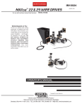
1. LABELS REQUIRED AND LABEL LOCATIONS
All "K" series engines will display the required identification label as follows.
Location on K211K25 Series engines:
EPA LABEL LOCATION
(TOP VIEW OF ENGINE)
-
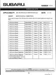
Emission compliance label (SAMPLE shown below)
<
\
g
E
Z
r-'
%
5
2
N
4.375 inch (111.125 mm)
P
EMISSION CONTROL INFORMATION
12003 D E ~
(
ENGINE FAMILY: 4NSXB02.147C ENGINE DISPLACEMENT: 2.1 LITER
JAN
ENGINE MAXIMUM POWER: 55.7 HP
THIS ENGINE IS CERTIFIED TO OPERATE ON LPG
MAR
ENGINE'S USEFUL LIFE IS 5000 HOURS OF OPERATION OR S E E N YEARS
t
MAY
EXHAUST EMISSION CONTROL TYPE: TBI, TWC, HO2S
TEST MODE: VARIABLESPEED ONLY
JUL
IDLE SPEED
NOOTHERADJUSTMENTSNEEDED.
0.38 MM (HOT)
VALVELASH
SEP
SPARK PLUG GAP 0.9 MM
OCT
APR
Em
AUG
1.
THlS ENGINE MEETS CALIFORNIAAND U.S. EPA REGULATIONS
FOR 2004 LARGE NONROAD ENGINES
NlSSAN MOTOR CO LTD I
K21L
'
:
FC
2. WARRANTY
The following statement is hereby provided as required by regulations of the United States Environmental Protection Agency (EPA).
YOUR WARRANTY RIGHTS AND OBLIGATIONS
All off-road large spark-ignition (LSI) engines must be designed, built and equipped to meet the Federal EPA's
stringent anti-smog standards.
Komatsu Forklift USA, Inc. ("KFI") must warrant the emission control system on your engine for the periods of time
listed below provided there has been no abuse, damage, neglect or improper maintenance of your engine.
Your emission control system may include parts such as the carburetor, regulator or fuel-injection system, ignition
system, engine computer unit (ECM), catalytic converter and air induction system.
Also included may be sensors, hoses, belts, connectors and other emission-related assemblies.
Where a warrantable condition exists, an Authorized Komatsu Forklift Dealer will repair your LSI engine at
no cost to you, including diagnosis, parts and labor.
MANUFACTURER'S WARRANTY COVERAGE
Beginning January 1, 2004 off-road large spark-ignition EPA engines are warranted for the time periods listed
below. If any emission-related part on your engine is defective, the part will be repaired or replaced by an Authorized Komatsu Forklift Dealer.
OWNER'S WARRANTY RESPONSIBILITIES
As the off-road LSI engine owner, you are responsible for the performance of the required maintenance listed in
your Operation and Maintenance Manual.
KFI recommends that you retain receipts covering maintenance on your off-road engine, but KFI cannot deny warranty solely for the lack of receipts or for your failure to ensure the performance of all scheduled maintenance.
As the off-road large spark-ignition engine owner, you should be aware, however, that KFI may deny you warranty
coverage if your off-road large spark-ignition engine, or a part thereof, has failed due to abuse, damage, neglect,
improper maintenance or unapproved modifications.
Your engine is designed to operate on gasoline and/or LPG fuel. Use of any other fuel may result in your engine no
longer operating in compliance with the Federal EPA's emissions requirements.
You are responsible for initiating the warranty process. It is suggested that you present your off-road large sparkignition engine to an Authorized Komatsu Dealer as soon as you become aware that a problem exists. The warranty repairs should be completed by the dealer as expeditiously as possible.
If you have any questions regarding your warranty rights and responsibilities, you should contact Komatsu's Product Support Dept. at 1-770-385-4815.
In addition to the standard warranty periods, the components listed below are covered by the following specific
warranty periods.
EMISSION CONTROL WARRANTY - 36 MONTHS OR 2,500 HOURS FOR GENERAL PARTS
For the first 2,500 operating hours, or for a period of thirty-six months from the date of the first use by the original
purchaser from an Authorized Komatsu Forklift Dealer, whichever occurs first, KFI warrants the
following emission-related parts:
Oxygen sensor
Water temperature
sensor
LPG injector
LPG solenoid
Mass air flow sensor
Ignition coil
Camshaft position sensor
.
.
.
.
.
.
.
PCV valve
Gasoline injector
LPG pressure sensor
LPG switching module
Throttle chamber
Crankshaft position sensor
Distributor
Spark plugs
EMISSION CONTROL WARRANTY - 36 MONTHS OR 4,000 HOURS FOR POWER TRAIN PARTS
Intake manifold
Exhaust manifold
EMISSION CONTROL WARRANTY - 60 MONTHS OR 3,500 HOURS FOR GENERAL PARTS
ECM
Catalytic converter
Vaporizer
I
NOTICE
I
Follow the instructions i n the Operations Manual concerning any other maintenance programs not
required for EPA compliance.
For questions and additional information concerning EPA Diesel Engine Exhaust Regulations, contact:
Komatsu Forklift USA, Inc.
14481 Lochridge Blvd., Bldg. #2
Covington, GA 30014-4908
Voice phone: (770) 385-4815
Fax phone: (770) 385-4838
FEDERAL EPA EMISSION CONTROL STATEMENT FOR
OFF-ROAD DIESEL ENGINES (4D94E ENGINES)
Exhaust emissions produced by diesel engines are regulated by the United States Environmental Protection
Agency (EPA). This section presents information concerning the correct labeling, warranty, parts and maintenance
of 4D94E diesel engines in order to comply with current EPA regulations.
1. LABELS REQUIRED AND LABEL LOCATIONS
All certified 4D94E diesel engines will display the required identification label as follows:
4D94E diesel engines:
Labels will be affixed to all appropriate engines on KFI production trucks.
EMISSION CONTROL LABEL
I
4
I
IMPORTANT ENGINE INFORMATION
THlS ENGINE CONFORMS TO 2004 MODEL YEAR U.S. EPA REGULATIONS
LARGE NONROADAND COMPRESSION IGNITION ENGINES
THlS ENGINE IS CERTIFIED TO OPERATE ON "USZD" FUEL
ENGINE FAMILY: 4YDXL2.78P4N DISPLACEMENT: 2.776 LITERS
ENGINE MODEL: 4TNE94-1B
EMISSION CONTROL SYSTEM: EM
FUEL RATE: 47.2 MM3 ISTROKE r@ 44.6 kW I2450 RPM
REFER OWNER'S MANUAL FOR MAINTENANCE SPEClFlCATlONS
AND ADJUSTMENTS
d
@ YANWR
DIESEL ENGME Co., Ltd.
J
)
2. WARRANTY
The following statement is hereby provided as required by regulations of the United States Environmental Protection Agency (EPA).
YOUR WARRANTY RIGHTS AND OBLIGATIONS
The Federal EPA and Komatsu Forklift USA, Inc. (hereinafter referred to as "KFI") are pleased to explain the emission control system warranty on your 2004 or later Diesel heavy duty off-road engine. All new, heavy-duty off-road
engines must be designed, built and equipped to meet the EPA's stringent anti-smog standards. KFI must warrant
the emission control system on your engine for the period of time listed below, provided there has been no abuse,
damage, neglect or improper maintenance of your engine.
Your emission control system may include parts such as fuel injection pump. Also included may be hoses, belts,
connectors and other emission-related assemblies.
Where a warrantable condition exists, an authorized Komatsu dealer will repair the heavy-duty off-road engine at
no cost to the owner, including diagnosis, parts and labor.
Now, KFI hereby certifies that diesel engines for lift trucks produced in 2004 model year and after shall be regulated by Federal EPA exhaust gaseous regulations. The difference between current and EPA-certified engines is
only the label attached on the engine. See available drawing and/or illustration of emission label and its location.
MANUFACTURER'S WARRANTY COVERAGE
Beginning January 1, 2004 heavy-duty off-road EPA engines are warranted for a period of five (5) years, or threethousand (3,000) hours of operation, whichever occurs first. If any emission-related part on your engine is defective, the part will be repaired or replaced by at an authorized Komatsu Forklift dealer.
EMISSION-RELATED PARTS
Fuel injection pump
Fuel injection nozzles
Turbocharger
OWNER'S WARRANTY RESPONSIBILITIES
As the heavy-duty off-road engine owner, you are responsible for the performance of the required maintenance
listed in owner's manual (Instruction Manual). KFI recommends that you retain all receipts and records covering the
maintenance on your engine, but KFI cannot deny warranty solely for the lack of receipts and records or for your
failure to ensure the performance of all scheduled maintenance. For your reference, the following is an emission
control maintenance schedule for certified Diesel engines.
Check oil level and coolant level - Everyday
Change of lubricating - Every 200 hours
Change lubricating oil filter - Every 200 hours
Initial adjustment of valve clearance - Every 200 hours
Change fuel filter - Every 500 hours
Check turbocharger, rebuild or replace if necessary - Every 2,000 hours
Adjust valve clearance - Every 2,000 hours
Check fuel injection nozzles, replace if necessary - Every 2,000 hours
Keep records to show proof of compliance with the required maintenance practices and intervals.
As the heavy-duty off-road engine owner you should, however, be aware that KFI may deny your warranty coverage if your heavy-duty off-road engine or part has failed due to abuse, damage, neglect,
improper maintenance or disapproved modifications.
Your engine is designed to operate on commercial diesel fuel only. Use of any other fuel in our engine
will result in the engine operating in non-compliance with the Federal EPA regulations.
You are responsible for initiating the warranty process. It is suggested that you present your heavy duty
off-road engine to an authorized Komatsu dealer as soon as you become aware that problem exists.
The warranty repair should be completed by the dealer as expeditiously as possible.
If you have any questions regarding your warranty rights and responsibilities, you should contact the
authorized KFI dealer.
LIMITATIONS
KFI is not responsible for resultant damages to an emission-related part or component resulting from:
Any application or installation KFI deems improper as explained in the Instruction Manual.
Attachments, accessory items or parts not authorized for use by KFI.
Improper off-road engine maintenance, repair or abuse.
Owner's unreasonable delay in making the product available after being notified of a potential product
problem.
This warranty is in addition to the KFI standard warranty applicable to the off-road engine product involved.
Remedies under this warranty are limited to the provision of material and services as specified herein. KFI is not
responsible for incidental or consequential damages, such as downtime or lost use of the forklift truck.
CUSTOMER ASSISTANCE - EMISSION CONTROL SYSTEMS WARRANTY
Komatsu Forklift aims to ensure that the Emission Control Systems Warranty is properly administered. In the event
that you do not receive the warranty service to which you believe you are entitled under the Emission Control Systems Warranty, call or write to your Komatsu Forklift Dealer.
Authorized dealers are recommended for major maintenance and repair work, as they are staffed with trained personnel, proper tools and are aware of the latest maintenance methods and procedures. Owners and others who
desire to perform their own work should purchase a service manual and obtain current service information from
their KFI engine dealer.
Follow the instructions in the Operations Manual concerning any other maintenance programs not
required for EPA compliance.
For questions and additional information concerning EPA Diesel Engine Exhaust Regulations, contact:
Komatsu Forklift USA, Inc.
14481 Lochridge Blvd., Bldg. #2
Covington, GA 30014-4908
Voice phone: (770) 385-4815
Fax phone: (770) 385-4838
01. SAFETY SECTION
1. SAFETY MANAGEMENT
WARNING
L
OPERATION MANUAL AND SAFETY LABELS
Read the instructions in this Manual and the Safety Labels attached to the various parts of the lift
truck, and make sure that you understand and follow them. If you do not understand or do not follow the instructions, this will lead to improper operation which may lead to damage, personal injury
or death.
Be sure that you understand the proper method of using the lift truck and the procedure for carrying out an inspection, and ensure that they are carried out safely.
Read this Manual and the Safety Labels again from time to time. If the Operation and Maintenance
Manual or Safety Labels have been lost or become dirty and cannot be read, obtain replacements
from your Komatsu Forklift distributorldealer and attach the Safety Labels in the specified positions.
I A WARNIN, I
OPERATING QUALIFICATIONS
This lift truck should be operated only by qualified personnel. Be sure you have proper qualifications before operating the lift truck.
When operating this lift truck, even if you have experience in operating other lift trucks, obtain
instructions from an authorized person who has experience in operating this lift truck or the same
type of lift truck.
A WARNING
CLOTHING AND PERSONAL PROTECTIVE ITEMS
Avoid loose clothing, jewelry, and loose long hair. They
can catch on controls or in moving parts and cause
serious injury or death.
Always wear a hard hat and safety boots.
Depending on the working conditions, wear other safety
equipment in addition to the hard hat and safety boots.
n
AWMLO
I A WARNING 1
OVERHEAD GUARD, LOAD BACKREST
Do not use this lift truck unless it is equipped with the overhead guard and load backrest shipped
with the lift truck from the factory by Komatsu Forklift.
01. SAFETY SECTION
Any modification made without authorization from Komatsu Forklift can create hazards.
Before making any modification whatsoever, consult your Komatsu Forklift distributorldealer.
Komatsu Forklift will not be responsible for any damage, injury or death caused by any unauthorized modification.
Do not install any equipment or parts which obstruct or limit the operator's view.
Do not leave the engine running where there is poor ventiliation.
The engine exhaust gas contains carbon monoxide. There is a
danger that this will cause gas poisoning which may result in
serious injury or death.
AW55060
1 A WARNING I
FIRE EXTINGUISHER AND FIRST AID KIT
If any abnormality in the lift truck occurs, stop operation immediately, park the lift truck in a safe
place and safe condition, then contact th'e person in charge.
Be sure that fire extinguishers have been provided and that you read the labels to ensure that you
know how to use them.
Know what to do in the event of a fire.
Be sure that you know the phone numbers of persons you should contact in case of an emergency.
Provide a first aid kit at the storage point.
Do not use the lift truck if it is leaking fuel. Inform
the person on charge of the nature of the abnormality, and repair the leakage before using the
lift truck.
Do not leave the lift truck with the engine running.
Always apply the parking brake securely, lower
the forks to the ground, stop the engine, and remove
~ 0 0 ~ ~ 7 0
the key before leaving the lift truck.
&
01. SAFETY SECTION
Do not operate the lift truck if you are fatigued, or when you have been drinking, or you have taken
any medication which can make you drowsy or sleepy.
When carrying out operation, inspection, or maintenance of the lift truck, always follow all work
shop rules, safety regulations and precautions.
During operation, always pay attention to safety and be careful of pedestrians, traffic and other
surrounding conditions.
CHECK WHEN TRAVELING IN REVERSE
When reversing, depending on the situation, an optional alarm, reversing lamp or rotary lamp
should be used. In all cases, be sure to face the rear and check around before traveling in reverse.
TRAVELING REGULATIONS ON PUBLIC ROADS
Always observe all traffic regulations when operating the lift truck.
Do not drive on public roads with the lift truck loaded.
Do not tow other machines on public roads. (Do not tow other machines even when not on public
roads).
Always carry your driver's license when traveling on public roads.
SAFETY EQUIPMENT
The overhead guard is installed to protect the operator from falling objects. It is designed to withstand the force of light boxes or small packages. It is not designed to withstand every possible
impact. Always be careful to prevent damage or injury from falling objects.
I A ~ A R N , N GI
TIRE FENDERS
The tire fenders prevent objects from being thrown up by the tires. When changing from a single
tire to a double tire arrangement on your forklift truck, always extend the tire fenders to cover the
additional tires. If the fenders are not extended, small stones and other objects will be thrown up
and may injure the operator or other people in the surrounding area.
INCORRECT
FENDERS
CORRECT
FENDERS
01. SAFETY SECTION
SAFE WORKING AREA
Always work on level surfaces and wipe up all oil or grease from the ground.
When working on quays, platforms, docks or other places where there is a danger of falling, set up
blocks to prevent the lift truck from going over the edge.
Put warning signs up in dangerous places to warn the operator not to approach.
Mark the travel areas clearly and maintain the road surfaces in good condition.
Put up signs to prevent unauthorized machines from entering areas where trucks are being
operated.
Ensure that there is adequate lighting to enable operations to be carried out safely.
WARNING
L
CLEAN OPERATOR'S COMPARTMENT
Keep the operator's compartment clean and tidy. Be sure to clean up all oil or mud. If the operator's hand or foot slips, this may lead to a serious accident.
Do not leave tools or spare parts lying around in the operator's compartment. They may damage
or obstruct the control levers or pedals. Always keep them in the tool box when not being used.
SAFE OPERATING PLAN
Before operation, establish an operating plan and hold a meeting to discuss operating safety.
In confined areas, position a signal person and carry out operations in accordance with hislher
instructions.
When carrying out operations on roads, put up fences around the working area and carry out operations in accordance with instructions from the signal person.
L
WARNING
REDUCE LOAD FOR LIFT TRUCKS WITH ATTACHMENT
The permissible load for any lift trucks equipped with an attachment is lower than the permissible
load for the standard lift truck.
Reason:
1) The permissible load must be reduced by an amount equivalent to the weight of the attachment itself.
2) Because of the thickness of the attachment, the load center moves forward.
Always observe the permissible load table strictly (this table is stuck to the lift truck or the attachment). Never exceed the permissible load.
I A WARNING I
"NO JUMP START" SAFETY PLATE (DECAL)
DO NOT JUMP START the engine by short circuiting the starting
motor terminals.
This SAFETY PLATE (DECAL) is located on the top center of the
starter's magnet switch.
If your machine is not equipped with this SAFETY PLATE, install a
new plate (decal) in the specified location after cleaning the surface.
01. SAFETY SECTION
WARNING
L
FIRE PREVENTION FOR FUEL
FUEL IS EXTREMELY FLAMMABLE AND CAN CAUSE FIRES AND EXPLOSIONS.
Carry out refueling away from flames or sparks.
Stop the engine when refueling.
*
After refueling, tighten the gas cap securely and wipe up any spilled fuel.
The specific gravity of LPG is heavier than air, so it is easy for the vapors to accumulate in low
places (holes, road surface depressions, etc.). This can create a fire or explosion hazard. Be
extremely careful!
Engine starting aids are highly flammable and may cause an explosion.
Do not use starting aids to start the engine.
WARNING
L
LPG SAFETY I FUEL SYSTEM SAFETY
Accidents involving fuel systems are always dangerous and can cause fire and explosion, serious
injury, death and property damage. Keep the following points in mind when working with fuel systems.
Read, understand and remember relevant information in the NATIONAL FIRE PROTECTION
AGENCY (NFPA) standard for fuel in use. Do this BEFORE working on any fuel system.
Ensure you are wearing proper personal protective equipment.
Check for fuel leaks before you begin work on any fuel system.
On LPG systems, DO NOT work on the system if the fuel storage container is filled with fuel past
the 80% liquid level.
Ensure there are NO SOURCES OF IGNITION nearby before beginning work.
Be sure your work area is adequately ventilated.
Disconnect the battery before working on the fuel system.
LPG is heavier than air and will sink to the lowest area possible. Avoid areas near floor drains or
lubrication pits where escaped fuel may collect.
LPG is stored under high pressure. Ensure the LPG fuel storage container valve is turned OFF
(closed), and pressure is released from the lines, before working on system.
Store all LPG cylinders OUTDOORS is a secured area and safe from any vehicle traffic.
NEVER WELD ON AN LPG PRESSURE VESSEL, STORAGE TANK OR CYLINDER.
LPG fuel tanks mounted horizontally MUST BE positioned properly. See MAINTENANCE Section.
Always utilize a UL listed LPG tank.
-
-
- -
--
01. SAFETY SECTION
2. SAFE TRAVEL
WARNING
L
PRECAUTIONS WHEN STARTING ENGINE
Before starting the engine, always check that the parking brake
is applied and that the directional and speed levers are in neutral.
Depress the clutch pedal (for clutch type trucks), or the brake
pedal (for TORQFLOW transmission trucks), firmly, and then start
the engine.
Adjust the operator's seat and the steering wheel before
starting the engine. Always lock them in position after
adjusting. Adjusting the seat or steering wheel during
operation is dangerous and it may cause you to lose
your balance or to operate the lift truck improperly.
Before starting the engine, check that the surrounding
area is safe. ALWAYS SIT IN THE OPERATOR'S SEAT
when starting the engine.
ABBOl120
Before starting the engine, sound the horn to warn people in the
area.
With large-sized lift trucks, get off the lift truck and walk around it to check that no one is near the
engine compartment, tires or counterweight, then get on the lift truck, sit in the operator's seat, and
start the engine.
Do not a t t e m ~to
t start the enaine bv short-circuitina the enaine startina circuit.
Such an act mav cause a serious bodilv iniurv or fire.
PRECAUTIONS WHEN OPERATING DIRECTIONAL OR
SPEEDLEVERS
When switching between FORWARD and REVERSE, always stop the lift truck. It is dangerous to
change the direction of travel suddenly.
When operating the directional lever or speed lever, always depress the clutch pedal before moving the lever (for clutch type lift trucks).
If the lever is moved without disengaging the clutch, the lift truck will move suddenly and may
cause injury.
I A WARNING I
If the load-engaging means or load is raised, the center of
gravity of the lift truck will also rise and increase the danger of
the lift truck tipping. Do not turn the lift truck when the forks are
raised high.
Do not suddenly raise the forks or tilt the mast to the front or
rear when the forks are loaded. There is danger that the
lift truck will tip.
Reduce speed before turning the lift truck. In particular,
when traveling unloaded, the rear of the lift truck is heavy.
If the lift truck is turned at high speed, there is a greater chance
of tipping than with the forks loaded.
Always ensure that the hood is properly latched.
ABBOIl3O
01. SAFETY SECTION
Do not turn, or travel across or at an angle on slopes.
There is danger that the lift truck will tip.
Before starting to drive up a slope, stop the lift truck and adjust
the clearance between the ground surface and the bottom of
the forks so that the bottom of the forks or pallet do not contact
the ground surface or the tip of the fork does not stick into the
ground when traveling.
For safe travel on slopes:
Travel FORWARD up the slope and in
When loaded:
REVERSE down the slope with the load
upgrade.
Travel in REVERSE up the slope and
When unloaded:
FORWARD down the slope with the loadengaging means downgrade.
When traveling down slopes, use the braking force of the
engine together with the foot brake, and travel slowly down the
slope.
WARNING
L
DO NOT JUMP OFF LIFT TRUCK EVEN IF IT TIPS
iVER JUMP OFF the lift truck even if it seems that it will tip. Alway
Hold the steering wheel securely.
Stay in the operator's seat.
Brace your legs.
If you jump off the lift truck when it turns over,
there is danger that you will be fatally crushed
under the lift truck.
Always stay in the operator's compartment if the
lift truck turns over, then escape from the lift truck
after it has stopped.
Always wear the seat belt correctly.
an'r risk injury ar deal&.
o as follows:
01. SAFETY SECTION
There is danger that soft road shoulders may collapse,
so do not go near them with the lift truck.
Always maintain a safe distance from the edge of road
shoulders and platforms.
I A WARNING I
LOADING HIGHWAY TRUCKS OR RAILROAD CARS
Do not travel on the edge of docks. There is danger that
the lift truck may fall, which may result in serious injury
or death.
Before starting operations, check the load limit for the gangplanks (dock boards), and do not use them if they do not
have ample strength to take the weight of the lift truck when
loaded.
Apply the brakes on the highway truck and block the wheels.
With trailers, use jacks and take steps to prevent the trailer
from sinking when the forklift truck travels on it.
When driving the forklift inside trucks, reduce speed when
backing out and be sure to check that the gangplanks are
safe.
Be careful of pedestrians.
Tell the truck driver not to move the truck until the operation is
completed.
If there is some system to secure the truck to the dock,
always use this system. Secure the gangplanks so that they
do not slip and fall.
WARNING
L
ESCAPING FROM A RAILROAD CROSSING
If engine trouble occurs on a railroad crossing and the lift truck cannot move, you cannot use the
starting motor to move the truck as can be done in automobiles. The lift truck's neutral safety
switch prevents this action.
In such an emergency, light a flare or smoke candle, to warn approaching trains, vehicles and
pesons n the area that there is a broken down truck on the tracks.
It is critically important to remove the lift truck from the tracks as soon as possible.
01. SAFETY SECTION
FORKLIFT TRUCKS ARE ONE-PERSON MACHINES.
Do not allow any other person to ride on the truck under any circumstances.
Never allow anyone to act as an extra counterweight.
I A WARNING I
DRIVING IN REVERSE
When driving in REVERSE, turn to face the rear and
check the area directly behind the lift truck.
l
a
WARNING
OBSTRUCTION OF REAR VIEW WHEN USING LP GAS
FUEL
The LP gas cylinder partially blocks the view to the rear, so there is danger of hitting personnel or
products or buildings in the surrounding area.
Install backup warning devices (backup buzzer, rotating backup lamp, etc.) or backup confirmation
devices (rear view mirror, etc.) to warn personnel in the surrounding area and to confirm that the
area to the rear is safe.
Please contact your Komatsu Forklift distributor 1 dealer for details of installing such optional safety
and warning equipment.
LP GAS CYLINDER r=
\
CYLINDER IS INSTALLED
01. SAFETY SECTION
If the view to the front is obstructed by the load,
turn to the rear and drive the forklift truck in reverse.
When driving in reverse with a high load, use a
signal person to ensure the safety of the load and the
safety in the surrounding area.
I a WARNING I
CHECK BEFORE STARTING
When checking the lift truck before starting, follow the procedure given in this Manual, and do not
start the lift truck until all the checks have been completed.
If anything abnormal is found, inform the person in charge and carry out the necessary repairs.
Check that the lamps light up correctly. Replace any broken or inoperative bulbs.
L
WARNING
KEEP HANDS FREE FROM OIL AND WATER
Do not drive the lift truck if your hands are wet or covered with oil. Your hands will slip on the work
equipment control levers or directional lever, and this may cause a serious accident.
NEVER jump on or off the lift truck.
When getting on or off the lift truck, always stop the lift
truck and use the handrails and steps to ensure that you
support yourself.
Never hold any control levers or the steering wheel when
getting on or off the lift truck.
If there is any oil, grease or mud on the handrails or
steps, wipe it off immediately. Always keep these parts
clean. Repair any damage.
01. SAFETY SECTION
I A WARNING 1
ALWAYS SIT IN OPERATOR'S SEAT
Never operate the lift truck from outside the operator's compartment.
Always keep your body under the overhead guard.
Do not extend your arms and legs outside the operator's compartment.
880 1240
Always wear your seat belt correctly when on the operator's seat.
The seat belt will reduce the risk of injury.
Always check the seat belt mounts and check for any damage to
the seat belt itself. If any abnormality is found, repair or replace
the seat belt immediately.
A WARNING I
SAFETY WHEN STARTING
Before starting and moving the lift truck, check that the surrounding area is safe.
Before moving the lift truck, raise the forks (approx. 8 in. (20cm)
from the ground surface), and tilt the mast back.
Before moving the lift truck, release the parking brake.
Tilt back
'il
20cn
(Bin)
WARNING
L
BRAKING WHEN TRAVELING
Do not stop the engine when traveling. If the engine is stopped, the power steering (for lift trucks
with power steering) and power brake (for trucks with power brakes) will not work.
If the inching pedal is depressed, the braking effect of the engine will be lost.
Do not use the brake excessively. Do not rest your foot on the brake pedal or inching pedal unless
you are operating it.
If you do, the brake will overheat and the braking effect will be lost.
For TORQFLOW lift trucks, if you leave your foot on the inching pedal, the multiple disc clutch
inside the transmission will overheat. In the worst case, the clutch discs will be deformed and the
clutch will not function normally.
01. SAFETY SECTION
SAFETY DURING TRAVEL
Keep a clear view of the path of travel and observe for other traffic, personnel and safe clearances.
Yield the right of way to pedestrians,
When passing oncoming vehicles, reduce speed and keep a safe distance from the other vehicle.
In places where there are speed limits, observe the speed limit and maintain a safe distance from
other vehicles.
When traveling, always pay careful attention to the area
around your lift truck, particularly in the direction of travel or
when turning.
Do not pass other vehicles on narrow roads or at crossings
or other places where the view is poor.
When traveling through crossings or other places where
the view is poor, or when entering or leaving narrow roads,
stop and sound the horn to confirm safety before driving
on.
Even if you sound the horn, not everyone in the surrounding area will necessarily hear it. Always pay careful attention to the movements of people in the surrounding area.
When crossing roads or turning corners, stop and confirm
safety before continuing.
Always pay careful attention to the movements of people in
the surrounding area, and take steps to prevent people
from entering the working area.
L
WARNING
SAFETY DURING TRAVEL
Avoid traveling in places which are flooded or where there
are holes.
Do not try to drive the lift truck on soft ground.
Avoid curbs, rails, ditches or other obstacles, and do not
travel directly over them.
Do not travel on slippery road surfaces.
When entering buildings, check the weight limit of the floor
and be careful not to exceed the limit.
GIVE PRIORITY TO LOADED LIFT TRUCKS
When traveling on slopes or in confined areas, unloaded lift trucks should always give the right of
way to loaded trucks.
01. SAFETY SECTION
When going in or out of places with height or width limits:
Ensure that there is ample height and width for the lift truck to
pass.
Do not extend your hands or legs outside the lift truck.
Check that the surrounding area is safe.
Be careful of electric wires and other obstacles inside and
outside the building.
When turning while traveling forward, the counterweight will
swing far out. Keep an ample clearance from walls and other
objects to ensure safety.
When turning, travel slowly and be careful that the front or
rear wheels do not come off the ground. When turning on soft
road shoulders, there is danger that the rear wheels may
come off the road shoulder and cause the lift truck to tip.
When traveling downhill, it requires a longer distance for the lift truck to stop then when traveling
on level ground.
When traveling downhill, reduce the speed and make sure that you have ample room at the bottom of the slope to stop.
When traveling on wet surfaces, it requires a longer distance to stop then when traveling on normal road surfaces. Always have ample room to stop.
If there is any problem with the brakes or steering system of your lift truck, do not use another lift truck
to tow it.
There is danger that the lift truck may run away.
01. SAFETY SECTION
3. LOADING OPERATIONS
NO OVERLOADING
Do not load the lift truck over the capacity set forth in the
load capacity chart. If the rear wheels come off the ground
because of overloading, the lift truck cannot travel or turn.
There is also danger that it may tip.
Always check the load capacity chart to confirm the loading
capacity.
L
WARNING
DON'T GO UNDER FORKS
Never allow anyone to go under the load-engaging means or load
when it is raised.
The area under the forks is a danger area. If the forks
come down, the person under the forks may be
crushed, or seriously injured or killed.
Never allow anyone to go under the load-engaging means or load
even if it is elevated or sticked. It may fall down suddenly at any
moment.
WARNING
L
DO NOT LIFT PEOPLE ON FORKS
Do not use the forks to lift people. If the person falls from the forks
helshe may be seriously injured.
AD81 7W0A
01. SAFETY SECTION
WARNING
L
BE CAREFUL NOT TO GET CAUGHT OR FALL
Never put your hands or feet into the mast structure. There is danger that you will get caught in moving parts and be seriously injured.
Do not use the mast as a ladder. If you slip, there is danger that you
will fall.
I A WARNING 1
OPERATE FROM OPERATOR'S COMPARTMENT
Always operate the mast and forks from the operator's compartment.
NO UNSTABLE LOADS
Make sure that the center of gravity of the load is in line with
the center of the lift truck. Do not carry loads off-center. There
is danger that unbalanced loads may cause the lift truck to
tip.
Place the load so that it contacts the load backrest.
Do not handle unstable loads. If there is danger that the load
may fall off, secure it in position and take steps to prevent the
load from collapsing or falling.
When carrying stacked loads, tie with rope to prevent the
load from falling.
.
.
.
ABBO 1340
01. SAFETY SECTION
I)
DO NOT LOAD ABOVE HEIGHT OF LOAD BACKREST
Keep the height of the load within the height of the load backrest. Do not carry any load that is higher than the load backrest. If the load is higher than the load backrest, there is
danger that it will fall back on top of the operator.
This may lead to serious injury or death.
AB801350
A WARNING
DO NOT TILT MAST FORWARD WHEN LOADED
Do not tilt the mast forward when the forks are loaded and
raised. There is danger that the load may fall and that the lift
truck may tip.
Do not travel with the mast tilted forward.
Do not load and unload on slopes.
L
WARNING
KEEP TENSION ON CHAIN
If there is any slack in the chain, the mast rail or forks may
catch in the load or a shelf, and there is danger that the load
may fall and the lift truck tip.
Always be careful that there is no slack in the chain when
pulling the forks out from a pallet or shelf.
5
01. SAFETY SECTION
USE ONLY FOR INTENDED PURPOSES
Do not use the lift truck for anything other than the intended
use (loading operations using the forks).
Do not use the forks to open or close the doors of railroad
cars or warehouses.
Do not push any other vehicle.
Do not hook ropes or cables on the forks and use the forks to
lift loads.
Do not use the drawbar pin for towing operations.
AM01380
L
WARNING
LEVER OPERATION
Be careful not to operate the lever by mistake. There is danger that the forks or work equipment
may cause serious injury.
Do not operate the levers when getting off the lift truck.
USING D W B A R PIN
{ A WARNING 1
Do not use the drawbar pin for
towing other lift trucks, for being
towed by other lift trucks, or for
lifting operations.
The drawbar pin installed to the rear of the counteweight is
used only to free the truck when the tires have become stuck
in mud or in a ditch and the lift truck cannot move, or when
loading the lift truck on to a trailer or truck.
01. SAFETY SECTION
WARNING
L
FIT FORKS SECURELY IN POSITION
When adjusting the position (width) of the forks, be careful
not to get your hands caught.
After adjusting, check that the forks are held securely in position by the fork stopper. If the forks are not held in position,
there is a danger that the forks may move when the lift truck
is traveling and the load may fall off.
I,,,,,,,,
ADJUST CHAIN
Be sure the tension of the left and right chains is the same. (See CHECK BEFORE OPERATION).
If the tension is not the same, the load will be unbalanced even if it is loaded correctly in the center,
and there is danger that the lift truck may tip. (For details of adjustment, see page 2-26).
01. SAFETY SECTION
Do not allow the tips of the forks to get close to people.
The tips of the forks are pointed, so there is a risk that
they may cause injury.
Do not hook the tips of the forks under objects. If the
forks slip out, there is danger that the lift truck or object
may move unexpectedly.
L
WARNING
PEOPLE IN WORKING AREA
Do not allow anyone except the signal person in the working area.
Do not let any person or another lift truck come close during operation.
When working with a signal person, always follow their instructions.
WARNING
L
USE STRONG PALLETS AND SKIDS
Always be sure that the pallets and skids have ample strength. If broken or damaged pallets or
skids are used, there is a risk that the load may fall.
Be extremely careful when carrying long or wide loads. Raise
the load slowly and be careful not to touch anything in the
surrounding area.
Keep the load as low as possible and be sure to maintain the
balance.
When turning, operate slowly and be careful not to let the
load move.
01. SAFETY SECTION
I A WARNING I
OVERHEAD OBJECTS
Be careful not to let the mast, overhead guard or load contact
electrical wiring, pipes, sprinklers or roof beams. If the truck
hits such objects, there is a risk that the load will fall or the lift
truck will tip. When the forks are raised, the mast height
increases, so be particularly careful when the forks are
raised.
Do not use the forks to push or pull loads. There is a risk that
the load will be damaged or fall.
PRECAUTIONS WHEN LOADING I UNLOADING
Do not let anyone place a load on the forks.
Do not let anyone remove a load directly from the forks.
Standing on the forks is dangerous because the forks are slippery and the load may move.
Do not use anyone to keep the load stable. The lift truck may move unexpectedly, causing the load
to fall and crush the person.
01. SAFETY SECTION
4. STOPPING AND PARKING
PRECAUTIONS WHEN STOPPING OR PARKING
Observe the following procedure when stopping or parking the lift
truck:
1) Stop the lift truck on level ground.
2) Apply the parking brake securely to make sure that the lift
truck cannot move.
3) Set the directional lever and the speed lever to neutral.
4) Lower the forks to the ground.
5) Turn the key switch OFF to stop the engine.
6) Remove the key from the key switch. hen get off the lift
truck.
( A WARNING I
PARK'NG
Park the lift truck in the specified place.
Park the lift truck on a firm surface.
Do not park near any emergency exit, stairway, fire extinguisher or other safety equipment. Park
the lift truck in a place where it will not obstruct pedestrians or other vehicles.
Never park the lift truck near any flammable object.
When parking the lift truck on a slope, park as specified above (PRECAUTIONS WHEN STOPPING OR PARKING), then put blocks under the tires to prevent the lift truck from moving.
Do not park near any holes for construction or elevator shafts. If LPG leaks, it can accumulate and
cause fire or explosion.
01. SAFETY SECTION
PARKING MACHINE AFTER FAILURE
If the lift truck has suffered a failure and the lift truck must be
parked without lowering the forks, put markers on the tips of
the forks and take steps to prevent pedestrians or other vehicles from hitting the forks.
Select a parking place where people or vehicles do not pass,
and stop the lift truck so that it is difficult for anyone to go
under the forks. (The area under the forks is a DANGER
zone).
Place a stand or something similar under the inner mast rail
or forks to prevent unexpected drop of the forks.
Remove the key from the faulty lift truck and hang signs in the
operator's compartment to prevent its use.
L
WARNING
ABRUPT LOWERING OF STUCK FORK
Because a stuck fork may drop down unexpectedly, do not go under the fork when it is in this condition.
Be very careful when dealing with this problem to prevent damage or injury, and warn those in the
work area.
01. SAFETY SECTION
5. INSPECTION AND MAINTENANCE
USE QUALIFIED PERSONNEL FOR INSPECTION AND
MAINTENANCE
Only persons authorized by the owner or operator of the equipment and having proper certification
(local or national) may carry out inspection, maintenance and repairs of the lift truck.
If inspection, maintenance or repair work is carried out incorrectly, it is very dangerous.
+
When carrying out inspection and maintenance, use a level, dry, dust-free area.
If the work is carried out inside a building, make sure that there is ample ventilation.
u
WARNING
PRECAUTIONS FOR INSPECTION AND MAINTENANCE
To be prepared in the event of a fire, have a fire extinguisher nearby and make sure that you know
how to use it.
Before carrying out inspection, lower the forks to the ground and stop the machine.
Do not run the engine unless it is necessary.
Place the directional lever, speed lever and work equipment control levers in neutral.
PRECAUTIONS WHEN CARRYING OUT INSPECTION
AND MAINTENENCE
Wipe off any oil or grease. Immediately wipe up any oil that has leaked. If the lift truck is dirty, it
becomes difficult or impossible to find cracks or other problems. Always clean the lift truck before
starting inspection.
Do not smoke or allow any flame to exist under any circumstances. Do not use any cloth which is
soaked in fuel, flammable solvent, oil or grease. There is danger that it may catch fire.
Wear suitable clothes for the job.
Use suitable safety and protective equipment (hard hat, safety boots, safety glasses, gloves) for
the job.
When working on top of the lift truck, be careful not to fall.
Do not put your feet under the forks.
When opening or closing the floor plate or engine hood, be careful not to get your hands or body
caught.
When carrying out inspection with the forks raised, insert a stand under the inner mast to prevent
the forks and mast from dropping.
When carrying out the job with another worker, decide who is the leader and carry out the job in
accordance with instructions from that person.
After repairing, make sure that the trouble has been corrected by performing a trial run.
During the trial run, start and operate the lift truck carefully because it is possible that the trouble
has not been fully corrected or that defective parts have not been removed.
01. SAFETY SECTION
Always use tools that are suited for inspection and maintenance.
It is extremely dangerous to use broken tools or tools
designed for another purpose.
L
WARNING
REPLACE SAFETY CRITICAL PARTS PERIODICALLY
Even if no abnormality is found, always replace safety critical parts periodically. As time passes,
these parts deteriorate and may cause fire or failure in the work equipment system.
However, if these parts show any abnormality before the replacement interval has passed, they
should be repaired or replaced immediately.
PRECAUTIONS WITH HIGH TEMPERATURE COOLANT
Immediately after using the lift truck, the engine coolant is at
high temperature (HOT!) and high pressure. Do not remove
the radiator cap under these conditions. Hot water may spurt
out and cause burns.
When removing the radiator cap, use a rag and turn it slowly
to release the internal pressure.
When checking the coolant level, stop the engine and wait for
the engine to cool down before checking. For lift trucks
equipped with a sub-tank or reservoir, check the level in the
sub-tank.
When adding water on lift trucks equipped with a sub-tank,
add the water to the sub-tank.
01. SAFETY SECTION
*
PRECAUTIONS WITH HlGH PRESSURE, HlGH
TEMPERATURE OIL
Immediately after using the lift truck, the oil is at high temper- INCORRECT
ature. Do not drain the oil or replace the filter when the oil is
hot. Hot oil may spurt out and cause burns.
When carrying out inspection and maintenance, wait for the
oil temperature to go down, and carry out the operation in the
order given in this manual.
Do not forget that the work equipment circuits are always
under pressure. Do not add oil, drain oil or carry out maintenance or inspection before completely releasing the internal
pressure. (For details on releasing the oil pressure, see page
3-37).
If oil is leaking under high pressure from holes, it is danger- CORRECT
ous if the jet of high-pressure oil hits your skin or eyes.
Always wear safety glasses and thick gloves, and use a piece
of cardboard or a sheet of plywood to check for oil leakage.
Release the internal pressure before checking the accumulator piping.
If you are hit by a jet of high-pressure oil, consult a doctor
immediately.
A0055180
A035190
ROTATING FAN AND BELT
It is extremely dangerous if you or any tool touches or gets caught
in the fan or fan belt when the fan is rotating. Never touch the fan
when it is rotating.
Always stop the engine before inspecting rotating parts.
When inspecting the areas around rotating parts, do not allow
anything to come close which may get caught.
01. SAFETY SECTION
HANDLING TIRES
Disassembly and assembly of tires should be carried out by a tire dealer.
The tire pressure is extremely high, so caution is needed when handling tires.
The wheel is fitted with mounting (lug) nuts. It also has rim nuts and bolts used to join the rim
halves. When removing the tire from the lift truck, do not loosen the rim nuts and bolts. The tire is
under high pressure, and there is a significant risk that the rim nuts and bolts may fly off. Relieve
tire inflation pressure before removing.
When the tires have been replaced, carry out a test drive and check again for any loose mounting
bolts. If the tightening torque is low, tighten to the specified torque.
l
a
WARNING
JACKING UP LlFT TRUCK (when checking or replacing
tires)
Do not go under the fork lift truck when it is jacked up.
Check the following before jacking up the lift truck. (For details,
see page 3-41).
1) Check that there is no one on the lift truck.
2) Check that there is no load on the forks.
When jacking up, stop when the tires come off the ground surface. Put blocks under both sides of the frame to prevent the lift
truck from coming down.
Put blocks under any tires contacting the ground to prevent the
lift truck from moving.
WARNING
LIFTING LlFT TRUCK (when checking tires)
Lift truck slinging work should be carried out by a qualified
person who has completed a course in correct lifting methods.
Fit wire ropes to the specified lifting points.
When lifting the lift truck, check that the wire ropes have
ample strength and are not damaged.
Block the tires contacting the ground to prevent the lift truck
from moving.
Insert blocks to prevent the lift truck from coming down.
Do not go under the lift truck during the lifting operation.
If the specified lifting point is the counterweight, check that
the counterweight mounting bolts are tightened to the specified torque before carrying out the lifting operation. Check
also that there is no damage to the lifting portion on the counterweight.
AB80 1540
01. SAFETY SECTION
BE CAREFUL NOT TO GET CAUGHT OR FALL
NEVER put your hands or feet into the mast structure. There
is danger that you will get caught in moving parts and be seriously injured.
Do not use the mast as a ladder. If you slip, there is danger
that you will fall.
I
,,,,,,I
CHECKING AND INFLATING TIRES
If the tire inflation pressure is low, it will affect truck stability.
However, do not inflate the tires immediately. The inflation pressure may have gone down because of damage to the rim. If the
rim is damaged or cracked and the tires are inflated, there is
danger that the rim will break when the tire is under high pressure, and this may cause personal injury or death.
For safety, when checking tire pressure, place your body in
front of the tread face of the tire. Do not check from the side
face of the tire.
Suitable qualifications are needed for tire inflation work. Always
have the work carried out by properly qualified personnel.
The tire inflation pressure on a forklift truck is several times
higher than the pressure on an automobile. When the tires are
being inflated, there is danger that dirt or dust may be thrown
up by the compressed air and enter your eyes. Always wear
safety glasses to protect your eyes.
AB801510
01. SAFETY SECTION
BATTERY HAZARD PREVENTION
Battery electrolyte contains sulfuric acid and can quickly burn the skin and eat holes in clothing. If
you spill electrolyte on yourself, immediately flush the area with a large quantity of water.
Battery electrolyte can cause blindness if splashed into the eyes. If electrolyte gets into your eyes,
flush them immediately with large quantities of water and consult a doctor at once.
If you accidentally drink electrolyte, drink a large quantity of water or milk mixed with beaten egg
white or vegetable oil. Call a doctor or poison control center immediately.
When working with batteries, ALWAYS wear safety glasses or goggles.
Batteries generate hydrogen gas. Hydrogen gas is highly EXPLOSIVE, and is easily ignited with a
small spark or flame. Do not smoke or create any spark near a battery.
Before working with batteries, stop the engine and turn the starting switch to the OFF position.
When removing the battery, remove the cable from the negative (-) terminal first. When installing the battery, install the
cable to the positive (+) terminal first. This prevents possible
sparks or arcing between the positive terminal and the positive
cable.
Avoid short-circuiting the battery terminals through accidental
contact with tools or other metal objects across the terminals.
Tighten the battery terminals securely. Loose terminals can
generate sparks and lead to an explosion.
When removing or installing the battery, confirm which is the
CHECK BATTERY
positive (+) terminal and which is the negative (-) terminal. Be
TERMINAL
careful not to connect the cables to the opposite I incorrect terminals.
Tighten the battery caps securely.
When cleaning the battery, leave the battery caps tightened.
BATTERY
A00551 00A
DO NOT PUT METAL OBJECTS ON TOP OF BATTERY
Never place any metal objects on top of the battery. There is danger that they will cause a short circuit and start a fire.
LPG FUEL TANKS
Only trained and certified personnel may change LPG tanks.
Turn ignition switch to the OFF position.
Change LPG tanks in designated and well ventilated area approved for this operation.
Check LPG tank and lines for fuel leaks.
Ensure no sparks, flame or ignition sources are present.
Once the full tank is in place, ensure it is mounted correctly and securely. Check all connections.
Do not attempt to start the truck until all LPG odor is gone.
If the truck is hard to start, contact a certified mechanic to repair the problem. Tag the truck "Out of
Service" until properly repaired.
01. SAFETY SECTION
When the battery is charged, hydrogen gas is generated and the battery is heated by the chemical
change. To prevent the danger of gas explosion, always do as follows:
Carry out the charging operation in a well-ventilated place.
Do not smoke or allow any flame.
Start the charging operation when the temperature of the battery electrolyte is below 95" F (35" C).
If the electrolyte temperature goes above 122" F (50" C) during the charging operation, wait for it
to go down below 95" F (35" C) before starting charging operation again.
When using a battery charger to charge the battery, take the battery caps off.
STARTING WITH BOOSTER CABLES
ALWAYS wear safety glasses or goggles when starting the lift truck with booster (jumper) cables.
When starting using the battery of another lift truck, do not allow the two lift trucks to touch.
Stop the engine before connecting the cables.
Be extremely careful not to let the cables get caught in the fan or fan belt.
Connect the batteries in parallel; positive-to-positive and negative-to-negative. NEVER connect
positive to negative.
DO NOT short-circuit the starter terminals to start a forklift truck.
WARNING
L
DO NOT PUSH START
Do not push the lift truck to start the engine. There is danger that the lift truck may suddenly start
and operate unexpectedly.
HANDLING BRAKE FLUID
It is dangerous if the brakes do not work because, in this condition, the lift truck cannot be stopped.
Always do the following:
Check the level of the brake fluid periodically.
Always use the specified brake fluid.
Check that the breather of the brake fluid reserve tank is not clogged.
Be careful not to let dirt or dust get into the brake fluid reserve tank.
01. SAFETY SECTION
Antifreeze can be flammable. Keep away from flame when handling.
Antifreeze is poisonous, so do not drink it. If you drink it by mistake, drink large amounts of water,
vomit it out, and get medical attention immediately. Follow safety precautions on container.
1 A CAUTION (
WASTE MATERIALS
Obey appropriate laws and regulations when disposing of harmful
items and materials such as oil, fuel, solvent, filters and batteries.
INCORRECT
01. SAFETY SECTION
6. STRUCTURE AND STABILITY OF THE LlFT TRUCK
(TO PREVENT LlFT TRUCK FROM TIPPING)
To operate the lift truck safely, it is important to understand the structure and stability of the lift
truck.
I A CAUTION I
STRUCTURE OF LlFT TRUCK
A forklift truck consists basically of the lifting mechanism (the
forks and mast) at the front and the lift truck itself (with tires) at
the rear.
The front wheels of the lift truck act as the fulcrum, and the center
of gravity of the lift truck and center of gravity of the load are kept
in balance.
The relationship between the position of the center of gravity of
the lift truck and the center of gravity of the load is extremely
important for maintaining the safety of the lift truck.
CENTER OF G M V I T Y OF LOAD
The loads carried by forklift trucks come in various shapes
(and weights) from boxes to planks and long objects. To
judge the stability of the lift truck, it is important to distinguish
the position of the center of gravity for loads of various
shapes.
01. SAFETY SECTION
CAUTION
L
CENTER OF GRAVITY AND STABILITY
The stability of the lift truck is determined by the position of
the combined center of gravity resulting from the combination
of the centers of gravity of the lift truck and the load.
When the lift truck is carrying no load, the center of gravity
remains as it is, but when the lift truck is loaded, the combined center of gravity becomes the combination of the centers of gravity of both the lift truck and the load.
The position of the center of gravity of the load changes
according to whether the mast is tilted forward or back or
whether the mast is raised or lowered.
The position of the combined center of gravity of the lift truck
is governed by the following factors:
Size, weight, shape of load
Lifting height
Tilting angle of mast
Inflation pressure of tires
Acceleration, deceleration, turning radius
Condition of road surface, angle of road
Type of attachments
Center of
aravitv of
lift truck
Combined
Center of
aravitv
Center of
aravitv
of load
Center of
aravitv
of load
It is assumed that the lift
truck bodv is constant. ABaoleoB
STABLE RANGE OF CENTER OF GRAVITY
For the lift truck to be stable, the position of the combined center of
gravity must be inside the triangle (stable range of center of gravity)
formed by the ground contact points of the left and right front tires
and the center of the rear axle.
If the position of the overall center of gravity is in front of the front
axle, the front tires will form the fulcrum and the lift truck will tip to
the front. If the position of the combined center of gravity moves
outside the triangle forming the stable area for the center of gravity,
the lift truck will tip in the direction where the combined center of
gravity moves outside of the triangle.
01. SAFETY SECTION
CAUTION
L
MAXIMUM LOAD (weight and center of gravity of load)
The horizontal distance between the center of gravity of the
load on the forks and the load backrest of the forks, or the front
face of the forks (whichever is shorter), is called the load center.
The maximum load is the maximum weight of the load that can
be loaded at the standard load center. The relationship
between the maximum load and the load center is given in the
load capacity charts on the nameplate on the lift truck. If the
load center moves to the front of the forks, the overall center of
gravity also moves to the front, so this means that the load
must be reduced.
C i-'
W
I
ALLOWABLE LOAD
The allowable load is stamped on the nameplate to show
the relationship regarding the position of the load center,
the height of the fork and the maximum load. Before loading the forks, check that the load and load center are within
the permitted range on the stamped allowable load.
If the shape of the load is complex, set it so that the heaviest part of the load is at the center of the forks and set the
load close to the load backrest.
If the forks are loaded more than the allowable value, the
drive wheels will float during travel and the steering system
will not work. This is very dangerous. Furthermore, the lift
truck will tip over easily under this condition. Therefore, be
sure to keep the load below the allowable value and prop-
SPEED AND ACCELERATION
If a stationary object is not subjected to external force, it will remain stationary. In the same way, if a
moving object is not subjected to external force, it will continue to move at the same speed. This is
called inertia.
Because of inertia, a force is applied towards the rear when the lift truck starts to move, and is applied
towards the front when the lift truck stops. If the brakes are applied suddenly, there is danger of a large
force being applied towards the front which may make the lift truck tip or the load come off the forks.
When the lift truck is turned, a centrifugal force is applied to the outside from the center of the turn.
This force pushes the lift truck to the outside and makes it tip. The range of stability to the left and right
is particularly small, so it is necessary to reduce speed when turning, in order to prevent the lift truck
from tipping. If the lift truck is traveling with a raised load, the position of the overall center of gravity is
high, so the danger of tipping to the front, left or right becomes greater.
01. SAFETY SECTION
SAFETY LABEL LOCATIONS
Keep these labels clean. If a label (decal) comes off, stick it on again in the same location or replace with a
new one. Treat all labels (decals) in the same way whether they are safety related or not.
OF SHROUD
OF ENGINE HOOD)
LEFT AND RIGHT
FRONT WHEELS
d
OUTER RIMS OF LEFT AND
RIGHT REAR WHEELS
AWB2296B
See following pages for labels corresponding to numbered locations
in Figure above.
01. SAFETY SECTION
1. Prohibit the operator from riding on the
forks and lifting or lowering himself.
Never enter the area under the forks.
(Part No. 3EB-96-25840)
4. Never touch fan when rotating.
(Part No. 3EB-96-25770)
5. No one is ~ e r m i t k d
to ride the lift
truck together with the operator.
(Part No. 3EB-96-25740)
2. Do not put your hand on the mast!
(Warning to avoid getting hand caught)
(Part No. 3EB-96-25850)
3 , Caution before operating machine.
(Part No. 3EB-96-25760)
AWARNING
I
B e f o r e s t a r t i n o engine.
.Put g e a r s h i f t lever in
neutral.
. p u l l ~ a r t i n gl e v e r
I
01. SAFETY SECTION
6. Warning for operation (Decal)
(Part No. 3EB-96-25720)
A WARNING
SERIOUS INJURY OR DEATH MAY RESULT IF YOU FAIL TO FOLLOW THESE PRECAUTIONS!
Before O~eratinq
Do not operate or repair truck unless trained and authorized.
Read and understand all warnings and instructions in manuals
and on truck before operating.
Contact forklifl dealer for replacement manuals.
Check truck before use. If truck is in need of repair, do no1
operate until restored to safe condition.
Do not start truck if fuel is leaking or has leaked.
Ee sure load is centered and forks are completely under load.
Never tilt load with mast tilted forward.
Do not til: forward when elevated except to pick
up or deposit load.
Travel load or lifting mechanism low and tilted back.
Tipover can occur if operated improperly.
Do not jump if truck begins to tip over.
Hold on firmly and lean away from point of impact.
Avoid being trapped between truck and ground.
General Precautions
Operate truck only from operator's seat.
Keep lruck under control at all times.
Do not overload truck. Check r ~ p a c i t yplate for load weight
and load center.
Avoid any sudden starts, stops, turn or change of direction.
Obey traffic safety rules. Yield right-of-way to pedestrians.
Keep clear view of travel path. If load being carried blocks
forward view, travel with load trailing.
Slow down and sound horn when vision is blocked.
Watch clearances, especially forks, mast, overhead guard and
tailswing area.
Slow down tor turns and on uneven or slippery surfaces.
Avoid running over loose objects.
Never angle or turn on incline.
Travel with load uphill when loaded.
Travel with lifting mechanism downhill when empty.
Secure dockboard or bridgeplate properly.
Do not exceed rated capacity.
Use special care when operating on dockboard or bridgeplate.
Do not handle unstable loads or loosely stack loads.
Do not handle loads higher than load backrest.
Space forks as far as load permits.
Allow no one lo stand or pass under or near load or
lifting mechanism.
* Never place any pan of body Into mast slructure.
between mast and truck or outside truck.
Do not carry passengers on any part of truck.
Lifi no one under any circumstances.
* Do not operate without overhead guard and load
backrest.
Fill fuel or charge battery only in specified place.
Stop engine when fueling and avoid open flame or
sparks, and prov~deadequate ventilation.
Keep vent caps clear when charging battery.
Disconnect battery during serviang.
-
Before getting OHtruck, shift F-R lever and high-low
lever (clutch-type) to neutral position, fully lower
lifting mechanism and pull parking lever securely.
Shut ofl power when leaving truck unattended.
* Block wheels when parking on incline.
7. Warning for use of split rim (Only pneumatic tires)(Decal)
(Part No. 3EB-96-25750)
I
Deflate tire completely
before removing rim nuts.
I
01. SAFETY SECTION
8. Prevention of tip-over (Decal)
(Parts No. 3EB-96-25730)
9. Warning for handling LPGIFLAMMABLE GAS (Decal)
(Part No. 3EB-96-25780)
Ftammable LP-GAS
10. "NO JUMP START" Decal (Part No. 09842-A0481)
Located top center of starter solenoid.
01. SAFETY SECTION
11. LPG TANK CHANGE INSTRUCTIONS DECAL (On LPG Tank Bracket Base Plate)
LPO N E L CVUNDER REPUCEYEMT PROCEDURE
I. * D P * ) M - D O 4 - R l E L S M D U O I * m u s R L T * m A
BOURLIOfFuELIJmOl
I. REPUm FUU CO*TU*EI. (IE IYIm TO USE T e mRRECT SUE A W
P~PZ
m ~nn
OM PUTE. SECURELY mourn MO
POMO)(LB
r
b.
KUom
mn ,.-w ru mRMIlPOIYTI)Y1Ntl HOLE IN C
mn U M m FoMmm ovm Ur*mKETWAV.
O U .
12. LPG SAFETY MAINTENANCE DECAL (Right side of seat on hood upper surface)
I
RECOMMENDED SAFETY MAINTENANCE PROCEDURE
FOR LP QAS FUELED FORKLIFT TRUCKS
WARNING:wcus~~aombuaa*hwc~c.kwrlnma.*.~.uplngpo
[email protected]
mcaNnd~th.VuclluldmhwlddwbapmpaiypostUmQbyruingth.
loullnp pln or koy way.
Tha fuel valva ahould ba t u m d OR whan lha m v h l m la not In mla.
CutRtUngaahouldnotbaundInthaLPG*8~.
U r only Und.nnlUn -torlaa
or Fatory Y u l w l I M . d LPO*9 how
Mlbl*.I(*R p m a u n M U n n a n mqulnd.
All plp. lhra8d.d Iltllnga should ba Inalalled ualng an approved
~
I
W
~
L
wppand by clamp l o rnkllmh. c M l n g and we".
Tha LP-QAS wbmld v.ha ahould ba w l n d to an wtonutlcahul ofl nrltch (011
prawn a vruurn) to pnrrm h d u g a of
In Iha wml the IgnlUon la on
wllhoul tha .nglm Nnnlng.
awllthap~pun-ldorvwuurn.hu(ot(vah(a~rtoYa:
1. Turn M cyl1nd.r v h OR, dnt md N n q l m unffl II.(op.
?.I~aoto~PSlp..urnpvl01prIrurm*lonAw8.
A . P ~ ~ ~ d . I ~ u n l t . ~ n g d ~ .
r"-
n
d
noll.ton.
-
-~h.phnay~rsond.ryd.o.npw.tm-~pppuv
.vrtmncondntaotcroup.ntamgubtm.
3. Turn qI1nd.r M valw on. The prawn pwg. ahould mdnWn a mu
roadlng. If It d o n not, tha d m o l d valw or vvuurn ahulofl v a h muat ba
np.lrmd or raphcd. An 51la added lo LP-QAS to h d p d d u l Ink% If g u
am la
tha M@Indm apply v d w and .n(llm ahould ta l u m d
on. -A
m i l aourcn 01 IpnlUon. .nd ~ l l a th.
a ru. W a all of th.
~np.mb.lomyouturnlhaMurpp)ron.
Tha canpWa LPaysIrn .hould bm I m p ~ l a p.rlodWly.
d
O m k dl
hon tor war. conrmorp tor la.
and all pm tor durug..
NOTE F u d h o s a have a Ilmltad 11fa a x p . c ~ c l .Thay .hould ba cM.d for
adrlngnddrylngdueto.~.. H M w i t h v l a l b k ~ o l . ~ . a h o u l d b a
~ . U w o n l y U ~ L . b o n t o r * . ~ 1 F ~ Y u t l u l l l b . d L P O * 5
p.* fanplunnmtr
NO= Tha abovm Infomutlon la prov#.d as a puld.. Conault lha N.tloml Fire
Raraon
pmphH M tor (h.u l a u o n g . and handllng 01 l l q d h d
p.tro(.urn
p.ua.Gov.mnmUI u l a t y regulallona in your locality could vay.
Uwck wlth lha aulhortly havlng jurladlcllon to ba w n IMyou r n n t all of thelr
y.
COIItYt lha manufrtumr for datalied n w k a Infomutlon.
b
SERVICE WORK SHOULD BE PERFORMED BY
QUALIFIED PERSONNEL ONLY.
01. SAFETY SECTION
13. LPG FUEL SYSTEM DECALS
A. LPG LOW FUEL ALARM LIGHT (On dashboard t o left o f steering column)(OP)
KFOM0006
B. DUAL-FUEL SYSTEM FUEL CHANGE-OVER INSTRUCTIONS (On Air Cleaner housing)
(Not illustrated in Fig. AWB2296B)
FUEL CHANGEOVER INSTRUCTIONS
DUAL FUEL SYSTEM
s . SwrrcHlNG
CAUTION- FLAMMASLEu o u ~ ~WHEN
FROM LPTO UQUlD FUEL. BE SURE THAT THERE
IS NO S P I W G E OF LIQUID FUEL FROM THE CARBURETOR
FLOAT SYSTEM.
1. SHUT OFF BOTH FUEL UNES COMPLmLY BY PLACING SWITCH
IN THE OFF POSTION.
2. START ENGINEAND RUN UNTIL SYSTEM IS PURGED OF ALL FUEL
AND STOPS.
3. TURN SWITCH TO DESIRED FUEL SELECTION, LPG OR OASOUNE.
4. START ENGINEAS USUAL
-
14. FUEL LEVEL REQUIREMENTS GASOLINE AND LPG (On
dashboard over Fuel Gauge)(Dual-Fuel applications only)
GASOLINE TANK MUST
BE AT LEAST 114 FULL
WHEN OPERATING
02. GENERAL INFORMATION & SPECIFICATIONS
-
-
SPECIFICATIONS MAST DATA & FEATURES INDOOR & OUTDOOR TRUCKS
FG15HC-17
FG18HT-I 7
FG15HT-17
FG18ST-17
FGI 5ST-17
PNEUMATIC TRUCK SHOWN
02. GENERAL INFORMATION & SPECIFICATIONS
-
SPECIFICATIONS MAST DATA & FEATURES (CON'T)
MAXIMUM FORK
HEIGHT
in. (mm)
MAST HEIGHT in. (mm)*
Lowered
in. (mm)
Extended*
in. (mm)
FREE LIFT
in. (mm)*
"Free View" FG15118-17
2-Stage Free View (FV)
106.0 (2,690)
74.5 (1,890)
154.0 (3,910)
5.5 (140)
2-Stage Full Free View (FFV)
106.0 (2,690)
74.5 (1,890)
154.0 (3,910)
26.5 (670)
3-Stage Full Free View (TFV)
158.5 (4,025)
75.5 (1,920)
206.5 (5,245)
27.5 (700)
235.5 (5,980)**
106.5 (2,705)
283.5 (7,200)
58.5 (1,485)
NOTE: Specifications for 4-Stage Full Free View (QFV) masts are not indicated. Please consult your authorized dealer
for information and availability.
** Cushion Trucks Only
02. GENERAL INFORMATION & SPECIFICATIONS
-
TRUCK DATA PNEUMATIC TIRE LIFT TRUCKS (OUTDOOR)
GENERAL
Power Type
Gasoline
Gasoline
Gasoline
Operation Type
Sit Down
Sit Down
Sit Down
Capacity @ 24 in. (600 mm) Load Center
Ibs. (kg)
3.000 (1.360)
3.000 (1.360)
3.500 (1.580)
Load Distance from Center Axle (2-Stage)
in. (mm)
15.8 (400)
15.8 (400)
15.8 (400)
Load Distance from Center Axle (3-Stage)
in. (mm)
15.9 (405)
15.9 (405)
15.9 (405)
54.1 (1,375)
54.1 (1.375)
54.1 (1,375)
5.860 2,660)
5,930 (2,690)
6.380 (2.895)
Wheelbase
in. (mm)
WEIGHT
Service Weight (inc. 2-Stage STD MasVForks Ibs. (kg)
TIRES
Tire Size - Front
Pneumatic
- 10 - 10PR (I)
5.00 - 8 - 8PR (I)
6.50 10 1OPR (I)
6.50 10 - 10PR (I)
5.00 - 8 - 8PR (I)
5.00 8 8PR (I)
-
Number of Wheels - Front IRear
-
Tread (Center of Tires) Front IRear
x = Driven
2x12
2x12
-
- -
6.50
Tire Size Rear
Pneumatic
Pneumatic
Tire Type
2x 12
- -
35.0 (890) 1 35.0 (890)
in. (mm)
DIMENSIONS
Tilting Angle, 2-Stage (FV) Masts, Forward IBackward "
618
6 18
6 18
Tilting Angle. 3-Stage (TFV) Masts, Forward IBackward "
6 I6
6 16
616
-
Mast Height Lowered - 2-Stage Mast
-
Mast Height Extended 2-Stage Mast t
85.5 (2.170)
85.5 (2,170)
85.5 (2.170)
176.0 (4,470)
176.0 (4.470)
176.0 (4,470)
128.0 (3,250)
128.0 (3,250)
128.0 (3,250)
5.5 (140)
5.5 (140)
5.5 (140)
79.7 (2.025)
79.7 (2.025)
79.7 (2,025)
in. (mm)
87.6 (2.225)
87.6 (2.225)
89.0 (2,260)
in. (mm)
87.7 (2,230)
87.7 (2,230)
89.1 (2,265)
42.1 (1,070)
42.1 (1,070)
in. (rnm)
in. (mm)
-
Maximum Fork Height 2-Stage STD Mast " in. (mm)
-
Free Lift Height 2-Stage STD Mast
Height Overhead Guard
Length to Fork Face - 2-Stage Mast
-
Length to Fork Face 3-Stage Mast
Overall Width at Drive Tires
-
in. (mm)
in. (mm)
I
42.1 (1,070)
in. (mm)
Forks Thickness x Width x Length
in. (mm)
Carriage Width IITA Class
in. (mm)
Ground Clearance under Mast
Ground Clearance - Center of Wheelbase
Right Angle Stacking Aisle (2-Stage Mast) tt
Right Angle Stacking Aisle (3-Stage Mast) tt
Turning Radius -Outside
1.6 x 4.0 x 42.0 (40 x 100 x 1.070)
41 .O (1,040) 1 11
41.0 (1.040)111
41 .O (1.040) 1 11
5.5 (140)
5.5 (140)
5.5 (140)
5.3 (135)
5.3 (135)
5.3 (135)
in. (mm)
92.4 (2,345)
92.4 (2,345)
93.8 (2,380)
in. (mm)
92.4 (2.345)
92.4 (2.345)
93.9 (2,385)
76.6 (1,945)
76.6 (1,945)
78.0 (1,980)
in. (mm)
in. (mm)
in. (mm)
PERFORMANCE
Travel Speed. Forward - Loaded IUnloaded mph (klhr.)
11.8 (19.0) 1 12.4 (20.0)
11.5 (18.5) 1 12.1 (19.5)
Lifting Speed - Loaded IUnloaded (2-Stage) fpm (mmls)
-
Lifting Speed Loaded IUnloaded (3-Stage) fpm (mmls)
135 (685) 1 138 (700)
123 (625) 1 126 (640)
132 (670) 1 136 (690)
116 (590) 1 120 (610)
-
Lowering Speed Loaded IUnloaded (2-Stg) fpm (mmls)
98 (500) 189 (450)
96 (490) 189 (450)
Lowering Speed - Loaded IUnloaded (3-Stg) fpm (mmls)
96 (490) 179 (400)
98 (500) 169 (350)
Maximum Drawbar Pull - Loaded
Ibs. (kN)
Maximum Gradeability - Loaded 1 Unloaded at 1 mph
%
Service Brake - Operation IControl
Parking Brake - Operation IControl
3,730 (16.6)
31 123
39 123
35 121
Foot IHydraulic
Foot 1 Hydraulic
Foot IHydraulic
Hand IMechanical
I
Steerins Tvpe
I
3.730 (16.6)
3,210 (15.4)
TABLE CONTINUED ON NEXT PAGE
Hand IMechanical
Hand IMechanical
I
Hydrostatic Power
I
I
Hydrostatic Power
I
Hydrostatic Power
02. GENERAL INFORMATION & SPECIFICATIONS
DRIVE
Battery Voltage I Capacity (20 hour rating)
V/Ah
Engine Model
12/41
12/41
K2 1
K2 1
K21
12/41
Rated Output (SAE Gross)
HP (kW) @ rpm
60.1 (45) @ 2,950
60.1 (45) @ 2,950
65.7 (49) @ 2,900
Maximum Torque (SAE Gross)
Ib.ft (Nm) @ rpm
115 (156) @ 1,600
115 (156) @ 1,600
145 (197) @ 1.600
No. of Cylinders / Displacement
Cylinder Bore x Stroke
Fuel Tank Capacity
4 / 126 (2,065)
cu. in. (cm3)
in. (mm)
U.S. gallons (liters)
3.5 (89) x 3.3 (83)
I
9.8 (37)
OTHER
Relief Pressure - Maximum
Hydraulic Tank Capacity
Clutch
Transmission
Air Cleaner Type
psi (bar)
U.S. gallons (liters)
2,650 (182.7)
2.650 (182.7)
2.650 (182.7)
8.2 (31)
8.2 (31)
8.2 (31)
Dry Clutch
Torque Converter
Synchromesh
TORQFLOW
Cyclone
Cyclone
Cyclone
NOTE: Most values shown in this publication are rounded. Therefore, direct conversion between metric and English or
Imperial may be slightly different than displayed in this table. The performance of the machines is affected by the condition of
the vehicle and how it is equipped as well as the nature and condition of the operating area. If these specifications are critical
or if your needs exceed the specifications shown here, discuss the proposed application with your authorized dealer.
Optional masts, attachments, longer load dimensions and higher lifting heights may result in derating of the capacity. Contact your authorized dealer.
" Other mast heights available. See MAST DATA CHART for other mast heights. Contact your authorized dealer.
t Includes 48 in. (1,220 rnm) high Load Backrest. Contact your authorized dealer for additional information.
tt Add load length and clearance. Contact your authorized dealer.
02. GENERAL INFORMATION & SPECIFICATIONS
-
TRUCK DATA CUSHION TIRE LIFT TRUCKS
FG18ST-17
FGISST-17
GENERAL
Power Type
Gasoline
Gasoline
Operation Type
Sit Down
Sit Down
3,500 (1,580)
Capacity @ 24 in. (600 mm) Load Center '
Ibs. (kg)
3.000 (1,360)
Load Distance from Center Axle (2-Stage)
in. (mm)
15.4 (390)
15.4 (390)
Load Distance from Center Axle (3-Stage)
in. (mm)
15.4 (390)
15.4 (390)
47.2 (1.200)
47.2 (1,200)
5,940 (2,695)
6,450 (2.925)
Wheelbase
in. (mm)
WEIGHT
Service Weight (inc. 2-Stage STD MasUForks Ibs. (kg)
TIRES
Tire Type
-
Tire Size Front
Cushion
Cushion
1 8 . 0 ~ 12
6 ~118
18.0 x 6 x 12 118
Tire Size - Rear
14x4112~8
1 4 x 4 112x8
Number of Wheels - Front IRear
x = Driven
Tread (Center of Tires) - Front IRear
2x 12
in. (mm)
2x12
32.1 (815) 132.1 (815)
DIMENSIONS
"
717
717
Tilting Angle. 3-Stage (TFV) Masts, Forward IBackward "
7 15
715
Tilting Angle, 2-Stage (FV) Masts, Forward IBackward
Mast He~ght- Lowered - 2-Stage Mast
-
in. (mm)
-
Mast Height Extended 2-Stage Mast t
Maximum Fork Height - 2-Stage STD Mast
83.5 (2,120)
83.5 (2,120)
176.0 (4.470)
176.0 (4,470)
in. (mm)
128.0 (3,250)
128.0 (3,250)
in. (mm)
5.5 (140)
5.5 (140)
77.6 (1,970)
77.6 (1.970)
in. (mm)
79.3 (2.015)
80.9 (2.055)
in. (mm)
79.3 (2.015)
80.9 (2,055)
38.0 (965)
38.0 (965)
in. (mm)
'+
Free Lift Height - 2-Stage STD Mast
Height Overhead Guard
Length to Fork Face - 2-Stage Mast
-
Length to Fork Face 3-Stage Mast
Overall Width at Drive Tires
in. (mm)
in. (mm)
Forks - Thickness x Width x Length
in. (mm)
Carriage Width / ITA Class
in. (mm)
Ground Clearance under Mast
in. (mm)
Ground Clearance - Center of Wheelbase
1.6 x 4.0 x 42.0 (40 x 100 x 1.070)
37.0 (940) 1 11
37.0 (940) I 1 1
3.5 (90)
in. (mm)
4.0 (100)
Right Angle Stacking Aisle (2-Stage Mast) tt
in. (mm)
83.3 (2.115)
85.1 (2,160)
Right Angle Stacking Aisle (3-Stage Mast) tt
in. (mm)
83.3 (2,115)
85.1 (2,160)
67.9 (1,725)
69.7 (1,770)
10.3 (16.5) 110.3 (16.5)
10.3 (16.5)l 10.3 (16.5)
-
Turning Radius Outside
in. (mm)
PERFORMANCE
Travel Speed. Forward - Loaded IUnloaded mph (klhr.)
Lifting Speed - Loaded IUnloaded (2-Stage) fpm (mmls)
1
135 (685) 1 138 (700)
1
123 (625) 1 126 (640)
Lifting Speed - Loaded IUnloaded (3-Stage) fpm (mmls)
132 (670) 1 136 (690)
116 (590) / 120 (610)
Lowering Speed - Loaded IUnloaded (2-Stg) fpm (mmls)
98 (500) 189 (450)
97 (490) I89 (450)
97 (490) 179 (400)
98 (500) 169 (350)
4.610 (20.5)
4,610 (20.5)
-
Lowering Speed Loaded IUnloaded (3-Stg) fpm (mmls)
Maximum Drawbar Pull - Loaded
Maximum Gradeability - Loaded
Ibs. (kN)
%
41 120
371 18
Foot IHydraulic
Foot IHydraulic
Parking Brake Operation I Control
Hand IMechanical
Hand IMechanical
Steering Type
Hydrostatic Power
Hydrostatic Power
Sewice Brake -Operation IControl
-
TABLE CONTINUED ON NEXT PAGE
02. GENERAL INFORMATION & SPECIFICATIONS
DRIVE
Battery Voltage I Capacity (20 hour rating)
12/41
VIAh
Engine Model
12/41
K21
K21
Rated Output (SAE Gross)
HP (kW) @ rpm
60.1 (45) @ 2.950
60.1 (45) @ 2,950
Maximum Torque (SAE Gross)
1b.R (Nm) @ rpm
115 (156) @ 1,600
115 (156)@ 1,600
No. of Cylinders / Displacement
Cylinder Bore x Stroke
Fuel Tank Capacity
cu. in. (cm3 )
in. (mm)
U S . gallons (liters)
4 1126 (2,065)
4 / 126 (2.065)
3.5 (89) x 3.3 (83)
3.5 (89) x 3.3 (83)
6.6 (25)
6.6 (25)
2.650 (182.7)
2,650 (182.7)
OTHER
-
Relief Pressure Maximum
Hydraulic Tank Capacity
psi (bar)
U.S. gallons (liters)
Clutch
Transmission
Air Cleaner Type
II
5.8 (22)
5.8 (22)
Torque Converter
Torque Converter
TORQFLOW
TORQFLOW
Cyclone
Cyclone
I
I
NOTE: Most values shown in this publication are rounded. Therefore, direct conversion between metric and English or Imperial may be slightly different than displayed in this table. The performance of the machines is affected by the condition of the
vehicle and how it is equipped as well as the nature and condition of the operating area. If these specifications are critical or if
your needs exceed the specifications shown here, discuss the proposed application with your authorized dealer.
Optional masts, attachments, longer load dimensions and higher lifting heights may result in derating of the capacity. Contact your authorized dealer.
" Other mast heights available. See MAST DATA CHART for other mast heights. Contact your authorized dealer.
t Includes 48 in. (1,220 mm) high Load Backrest. Contact your authorized dealer for additional information.
tt Add load length and clearance. Contact your authorized dealer.
02. GENERAL INFORMATION & SPECIFICATIONS
PERIODIC REPLACEMENT OF CONSUMABLE PARTS
For operational safety, always perform specified periodic maintenance, and be sure to replace all consumable parts listed in the table below following the recommended schedule.
These parts may deteriorate in time and are susceptible to wear. It is difficult to estimate the degree of
wear at the time of your periodic maintenance, therefore, even if no wear is apparent, always replace the
items with new parts within the scheduled period.
Consumable parts must certainly be replaced sooner than the recommended intervals if wear, damage or
malfunction occurs earlier. An effective and timely inspection and maintenance program will reveal such
conditions before more serious damage occurs to the truck.
No.
I
Part Name
Period of
Replacement
1
Brake Master Cylinder and Wheel Cylinder caps
and dust seals
Every 1 year
2
Brake hoses and tubes
Every 1 to 2 years
3
Brake reservoir tank and tube
Every 2 to 4 years
4
Power steering hose
Every 2 years
5
Stop lamp switch (Oil pressure type)
Every 2 years
6
Fuel hoses
Every 2 to 4 years
7
Rubber parts of power steering assembly
Every 2 years
8
9
/ Lift chain(s)
Load handling hoses
Every 2 to 4 years
Every 1 to 2 years
02. GENERAL INFORMATION & SPECIFICATIONS
STANDARD TIGHTENING TORQUE FOR PIPE JOINTS
Elbows, nipples and unions
Width across Flats B (rnrn)
-
(
I
22
I
30
36
-
19
22
30
21.7 - 28.9
(29.4 - 39.2) (3 - 4)
57.9 - 75.9
(78.5 - 103) (8 - 10.5)
86.8 - 119.3
(117.7 - 161.8) (12 - 16.5)
314 - 16 UNF
718 - 14 UNF
--
Width D (rnrn)
Tightening Torque Wlbs.
(Nm) (kgfm)
Port Size (in.)
Tightening Torque Nrn
(kgfrn)
I
50.6 - 54.3
(68.6 - 73.6) (7 - 7.5)
I
UNION
ELBOW
High-pressure rubber hoses, pipes and sleeve nuts
Width across flats B (mm)
19
24
Bore A (mm)
Tightening Torque Wlbs.
57.9 - 61.4
(78.5 - 83.3) (8 - 8.5)
1
14.5 - 21.7
1
17.3 - 50.6
I
--
,,
02. GENERAL INFORMATION & SPECIFICATIONS
STANDARD TIGHTENING TORQUE FOR BOLTS
For unspecified bolts and nuts, use the torque values specified
in this list.
Select a proper torque value corresponding to the width across
the flats (b) of the bolt or nut.
When replacing bolts and nuts, always use the manufacturer's
specified part(s) of the same size and strength as the original
parts.
Thread diameter
of bolt -in. (mm)
(a)
Width across
flat in. (mm)
(b)
-
Tightening Torque
.
Ib.lft
Nm
kgfm
03. SERVICE DATA
-
-
SERVICE DATA GASOLINE ENGINE TRUCKS PNEUMATIC
Component
Check Item
I
Unit
FG15-17
I
FG18-17
ENGINE
Engine Model
Idling Speed
ENGINE
Maximum Speed
Torque Converter Stall Speed
rPm
rpm
Engine Oil Capacity
qts. (L)
Engine Oil Pressure @ 178" F (80" C)
(kPa)
Coolant Capacity IRadiator Cap Press.
I
2,100 5 100 rpm
I
3.91 (3.7) wl Filter 13.59 (3.4) wlo Filter
qts. IL
1
I
Idle: 14.22 (98)
At 2.000 rpm: 39.8 - 45.5 (274 - 313)
2.4 (9.1) 1 12.8 psi (0.9 kg/cm2)
in. (mm)
1
0.47 - 0.55 (12 - 14) Finger Pressure (98N)
--
I
Unleaded Regular Gasoline (89+ Octane)
BTDC"
I
Variable - Controlled by ECU
psi (Nm)
I
50.8 PSI (350 KPa)
Intake
in. (mm)
I
,015 (0.38) wl Engine Warm
Exhaust
in. (mm)
Fan Belt Tension
Fuel Type
lnjection Timing
FUEL SYSTEM
700
No Load = 3,600
(Instantaneous)
Continuous Load = 3.000
psi 1 rprn
(MPa Irpm)
Compression
LUBRICATING I
COOLING SYSTEMS
rPm
lnjection Order
lnjection Pressure
Fuel Tank Capacity
INTAKE I
EXHAUST SYSTEMS
ELECTRICAL
SYSTEM
Valve Clearance
I
.015 (0.38) w l Engine Warm
Spark Plug Gap
in. (mm)
,035 (0.9)
Spark Plug Type
--
PIN 22401-FU412
BTDC" Irpm
0" 1700
Firing Order
-
1-3-4-2
Battery Electrolyte Specific Gravity
--
I
Minimum 1,240
rpm
I
2,100 2 100 rprn
Ignition Timing
POWER TRAIN
Stall Speed
TORQUE
CONVERTER
Inlet Port Oil Pressure
psi Irpm
91.4 - 156.6 (0.63 - 1.08) 1 1,000
127.6 - 177.0 (0.88 - 1.22) 12,000
Outlet Port Oil Pressure
psi (MPa)
35.5 - 63.8 (0.245 - 0.440)
psi Irpm
(MPa Irpm)
(0.63 - 1.08 1 1,000)
127.6 - 176.9 1 2,000
(0.88 - 1.22 1 2,000)
Relief Pressure
TORQFLOW
TRANSMISSION
Clutch Actuation Pressure
Lubricating Oil Pressure
Oil Capacity
DIFFERENTIAL
psi (MPa)
I
12.68 (12) Including Torque Converter
qts. (L)
qts. (L)
Oil Capacity
Clutch Type
qts. (L)
Continued
14.5 - 56.6 (0.1 - 0.39)
I
6.34 (6)
13.74 (13) inc. Direct Drive Trans.
03. SERVICE DATA
Component
I
FG15-17
Check Item
Front tires
psi (MPa)
98.6 (0.68)
Rear tire(s)
psi (MPa)
98.6 (0.68)
in. (mm)
Minimum ,063 (1.6) (at tread width 114)
Inflation Pressure
TIRES
I Tread Depth
HUB NUT
I
Front Wheels
Ib./fl (Nm)
113.6 - 180.1 (154 - 245)
Rear Wheels
Ib./ft (Nm)
61.2 - 108.4 (83 - 147)
Front Wheels
Ib.1ft (Nm)
Tightening Torque
RIM
NUT
Tightening Torque
POWER STEERING RELIEF
VALVE
Relief Pressure
STEERING
WHEEL
Play
1 Rear Wheels I
Ib./ft (Nm)
Minimum Turning Radius
I
I
BRAKE
FORK
CHAIN
in. (mm)
I
76.6 (1,945)
78.0 (1,980)
Support Thrust Clearance
in. (mm)
0.028 (0.7)
Play
in. (mm)
0.12 - 0.2 (3 - 5)
Play
in. (mm)
0.08 - 0.12 (2 - 3)
Interconnected Travel
in. (mm)
1.85 - 2.09 (47 - 53)
Play
in. (mm)
0.51 - 0.67 (13 - 17)
INCHING PEDAL
BRAKE
43.5 - 54.6 (59 - 74)
1.2 - 2.4 (30 - 60)
in. (mm)
STEERING AXLE
BRAKE PEDAL
64.9 - 90.7 (88 - 123)
I
psi (MPa)
I
CLUTCH PEDAL
FG18-17
Pedal Height when Depressed
in. (mm)
3.15 - 3.54 (80 - 90)
Brake Fluid Capacity
qts. (L)
,158 (015)
Parking Brake Operating Force
Ibf (N)
55.1 (245)
Torque for Back Plate Mtg. Bolt
Ib.lft(Nm)
108.4 - 144.5 (147 - 196)
STOPPING
Unloaded
DISTANCES
Loaded
14.76 (4.5)
ft (m)
6.56 (2.0)
Thickness at Fork Root
in. (mm)
1.26 (32) Minimum
Difference in Height
in. (mrn)
Amount of Opening at Tip
in. (mm)
1.4 (35) Maximum
Length of 17 Links
in. (mm)
13.1 (332) Maximum
Hydraulic Drift (Lift Cylinder)
in. (mm)
20 (50) Maximum I
15 Minutes
Hydraulic Drift (Tilt Cylinder)
in. (mm)
1.8 (45) Maximum I
15 Minutes
0.6 (15) Maximum
CYLINDER
MAIN RELIEF
VALVE
Relief Pressure
HYDRAULIC
SYSTEM
Oil Capacity
I
psi (MPa)
1.34 (34) Minimum
I
03. SERVICE DATA
-
-
SERVICE DATA GASOLINE ENGINE LIFT TRUCKS CUSHION
Component
I
Check Item
I
Unit
I
FG15S-I7
FG18S-17
ENGINE
Engine Model
Idling Speed
ENGINE
No Load = 3,600 (Instantaneous)
Continuous Load = 3,000
Maximum Speed
Torque Converter Stall Speed
rPm
Compression
Engine Oil Capacity
LUBRICATING I
COOLING SYSTEMS
Engine Oil Pressure @ 178°F (80°C)
1
3.91 (3.7) wl Filter 13.59 (3.4) wlo Filter
psi
I
Idle: 14.22 (98)
At 2,000 rpm: 39.8 - 45.5 (274 - 313)
Coolant Capacity IRadiator Cap Pressure
2.4 (9.1) 1 12.8 psi (0.9 kgflcm2)
in. (mm)
0.47 - 0.55 (12 - 14) Finger Pressure (98N)
--
Unleaded Regular Gasoline (89+ Octane)
lnjection Timing
BTDC"
Variable - Controlled by ECU
Injection Order
--
4-2-1-3
-
Fuel Type
FUEL SYSTEM
+ 100 rpm
178 1250
(1.2 I250)
qts. (L)
Fan Belt Tension
-
2,100
psi Irpm
(MPa Irpm)
psi (MPa)
I
50.8 PSI (350 KPa)
Intake
in. (mm)
I
,015 (0.38) wl Engine Warm
Exhaust
in. (mm)
Injection Pressure
Fuel Tank Capacity
INTAKE I
EXHAUST SYSTEMS
ELECTRICAL
SYSTEM
Valve Clearance
I
,015 (0.38) wl Engine Warm
Spark Plug Gap
in. (mm)
,035 (0.9)
Spark Plug Type
--
PIN 22401-FU412
Ignition Timing
Firing Order
Battery Electrolyte
Specific Gravity
--
I
Minimum 1,240
POWER TRAIN
Stall Speed
TORQUE
CONVERTER
TORQFLOW
TRANSMISSION
rPm
2,100 2 100 rpm
Inlet Port Oil Pressure
psi Irpm
91.4 - 156.6 (0.63 - 1.08) 1 1,000
127.6 - 177.0 (0.88 - 1.22) 12,000
Outlet Port Oil Pressure
psi (MPa)
Relief Pressure
psi (MPa)
153.74 (1.06)
psi Irpm
(MPa Irpm)
91.4 - 156.6 1 1,000
(0.63 - 1.08 1 1,000)
127.6 - 176.9 12,000
(0.88 - 1.22 12,000)
Clutch Actuation Pressure
Lubricating Oil Pressure
Oil Capacity
DIFFERENTIAL
Oil Capacity
TORQFLOW
psi (MPa)
I
I
35.5 - 63.8 (0.245 - 0.440)
14.5 - 56.6 (0.1 - 0.39)
qts. (L)
12.68 (12) Including Torque Converter
qts. (L)
6.34 (6)
qts. (L)
Continued
1
13.74 (13) Inc. Direct Drive Trans.
03. SERVICE DATA
Component
I
Check Item
I
Unit
I
I
FG15S-17
Front tires
psi (MPa)
NIA
Rear tire(s)
psi (MPa)
NIA
FG18S-17
Inflation Pressure
TIRES
I
Tread Depth
I
NIA
Front Wheels
Ib.lft (Nm)
115.8 - 180.7 (157 - 245)
Rear Wheels
Ib.lft (Nm)
NIA
Front Wheels
Ib.lft (Nm)
NIA
Rear Wheels
Ib.1ft (Nm)
NIA
Relief Pressure
psi (MPa)
1,073.3 (7.4)
Play
in. (mm)
Tightening Torque
HUB NUT
in. (mm)
RIM MATING NUT Tightening Torque
STEERING I BR
POWER STEERING RELIEF
VALVE
STEERING
WHEEL
I
STEERING AXLE
Minimum Turning Radius
(
in. (mm)
1
Support Thrust Clearance
I
in. (mm)
I
Play
CLUTCHPEDAL
INCHING PEDAL
BRAKEPEDAL
BRAKE
CHAl N
in. (mm)
0.08-0.12 (2 - 3 )
InterconnectedTravel
in. (mm)
1.85 - 2.09 (47 - 53)
Play
in. (mm)
0.51 - 0.67 (13 - 17)
Pedal Height when Depressed
in. (mm)
3.15 - 3.54 (80 - 90)
Brake Fluid Capacity
qts. (L)
,158 (0.15)
Parking Brake Operating Force
Ibf (N)
55.1 (245)
Torque for Back Plate Mtg. Bolt
Ib.lft(Nm)
108.4 - 144.5 (147 - 196)
Unloaded
14.7 (4.5)
Loaded
6.56 (2.0)
VALVE
I
I Length of 17 Links
I
SYSTEM
1.34 (34) Minimum
0.6 (15) Maximum
in. (mm)
Difference in Height
1
1.26 (32) Minimum
in. (mm)
I Amount of Opening at Tip
CYLINDER
.12 - .20 (3 - 5mm)
in. (mm)
Thickness at Fork Root
FORK
69.7 (1,770)
0.028 (0.7)
Play
STOPPING
DISTANCES
BRAKE
1
67.9 (1,725)
in. (mm)
I
in. (mm)
I
1.4 (35) Maximum
13.1 (332) Maximum
Hydraulic Drift (Lift Cylinder)
in. (mm)
20 (50) Maximum 115 Minutes
Hydraulic Drift (Tilt Cylinder)
in. (mm)
1.8 (45) Maximum 1 15 Minutes
gal (L)
9.25 (35)
Relief Pressure
Oil Capacity
04. TESTING, ADJUSTING AND MEASURING
ADJUSTING IGNITION TIMING
Ignition timing is automatically set at 0" by the Electronic Control Unit (ECU) and it is not adjustable.
With the Special Service Tool (SST) attached and operating, the ignition timing may be temporarily changed
for diagnostic purposes, but once the SST is disconnected from the unit, the ignition timing will default back
I
ADJUSTING SPARK PLUG GAP
1. Using a proper spark plug removal tool, remove the spark
plug(s).
2. Carefully remove any soot or carbon buildup adhered to
the spark plug tip and surrounding area.
3. If the plug is burned or shows electrode damage, replace
the spark plug(s).
4. Measure the gap (A) with a gap gauge.
5. Set spark plug gap to .031 .035 in. (0.8 0.9 mm)
-
p
~
p
~
INSULATOR
TERMINAL
-
-&-PLUG
--
GAP
A
Spark Plugs - (Replace every 18 months13,600 hours)
04-0001
22401-FU412
Part Number
-
GAP: 0.31 0.35 in. (0.8 - 0.9rnrn)
,f-=
ADJUSTING VALVE CLEARANCE
1. Remove the cylinder head (valve) cover.
2. Rotate the crankshaft aligning the timing mark (white dot)
on the crankshaft pulley with the raised boss on the front
cover as shown at right.
3. Check that No. 1 cylinder or No. 4 cylinder is at piston
compression Top Dead Center (TDC). Both intake and
exhaust valves for that cylinder should be fully closed at
TDC.
4. Adjust valve clearance starting with the valves for the
cylinder at TDC.
NOTE: When No. 1 cylinder is at TDC:
Adjust the valve clearance of the valves marked "X"
Intake valve
I
I
X
1 x 1
X
I
I
1 0
0
I
CRANKSHAFT
PULLEY
I
TIMING MARK
(WHITE)
04-0002
- - -
I
(
+
1 3 4 2
ENGINE FIRING ORDER:
Exhaust valve
U
1
I
1 0 1
X
I
(
0
04. TESTING, ADJUSTING AND MEASURING
in the table above. Then rotate the crankshaft one
revolution clockwise (facing the pulley) and adjust
the clearance on the valves marked "0"in the table.
When No. 4 cylinder is at TDC:
Adjust the valve clearance of the valves marked "0"
in the table above. Then rotate the crankshaft one
revolution clockwise and adjust the valves marked
with an "X".
Loosen the locknut (1) of adjustment screw (2). Then
adjust the clearance between valve stem (3) and rocker
arm (4) using a straight bladed screwdriver on the
adjustment screw. When properly adjusted, the feeler
gauge should have a snug, sliding fit, but should not grab
or bind the gauge.
After adjusting the clearance to specification, tighten the
locknut, while holding the adjusting screw in position, to
lock down the adjustment screw (See Fig. 04-0003).
Recheck the clearance.
Reinstall the two valve cover bolts and washers and
tighten to 10 11.6 Wlbs (13.7 15.7 Nm).
-
-
The valve clearance must be finally adjusted when the engine is fully warmed up. Adjusting
the valves in a cold state after assembly will make final adjustments easier.
ADJUSTMENT OF FAN BELT
Inspect and adjust fan (accessory) belt with engine stopped.
1. Visually check for damage, cracks, wear and oil smears.
2. Ensure that the belt is not bottoming out in the pulley.
3. Check belt deflection by pressing on the belt at the center
between the pulleys.
Pressing Force
Fan Belt Deflection
I
1
22 Ibf (98N) (10 kg)
-
-
.43 .51 in. (11 13 mrn)
-
-
-
-
04. TESTING, ADJUSTING AND MEASURING
MEASURING ENGINE CYLINDER COMPRESSION
1. Start the engine and fully warm it up until the coolant
water temperature reaches 167" 185°F (75" - 85°C).
2. Stop the engine
3. Release the fuel pressure..
4. Remove the spark plugs.
5. Screw the end of the compression gauge into the
cylinder spark plug hole to be measured.
6. Set the throttle valve to the fully open position.
7. Depress the throttle (accelerator) pedal to the fully
open position.
8. Crank the engine over and read the gauge.
NOTE: Keep the engine cranking rpm at about 250.
This is normal cranking rpm at full charge.
Complete the compression measurement
process as quickly as possible.
-
COMPRESSION
GAUGE
Standard Compression Pressure
K21
178 psi (1,230 kPa 1 250 rpm)
9. The compression pressure differences between cylinders must not exceed 14.2 psi @ 250 rpm. If any
cylinder produces an extremely low compression pressure reading, put a small amount of oil into the
cylinder through the spark plug hole and remeasure.
If the pressure rises after adding oil to the cylinder, the piston ring is worn or damaged.
If the pressure remains unchanged after adding oil, the valve is stuck or i s not sealing
correctly.
If low compression pressure is observed in two adjacent cylinders and the pressure is
not restored after adding oil to those cylinders, the head gasket is leaking. In this case,
oil and water may enter into the combustion chamber.
If the engine RPM is not i n the specified range (250 rpm), check the battery specific
gravity.
MEASURING HYDRAULIC DRIFT ON LIFT & TILT CYLINDERS
PRECAUTIONS WHEN MEASURING DRIFT
When measuring drift, never allow anyone to go under the load.
Do not put your feet on the mast stays or dashboard or climb up when measuring the
hydraulic drift of the lift cylinder. There is a DANGER that you may get your hands or
feet caught in the mast.
Always use a strong, stable stand when measuring.
Before measuring, check that the hydraulic oil level is correct and that the hydraulic oil
is not dirty or mixed with any other brand of oil.
Always carry out the measurement on flat horizontal ground in front of a strong platform which will support the truck if it should tip over towards the front.
04. TESTING, ADJUSTING AND MEASURING
MEASURING PROCEDURE
Place a load on the lifting forks equal to or slightly less than the specified lifting capacity of the truck.
Secure the load to the lift truck with wire.
Bring the truck to a stop about 20 in. (500rnrn) in front of
the platform.
Operate the lift and tilt repeatedly to bring the oil
temperature to 122°F (50°C).
Raise the load about 60 in. (1,500rnrn) and set the mast
ERPENDICULAR
perpendicular to the ground.
Wait for 3 minutes. Then place a ruler against the lift
cylinder piston rod and make a mark.
Measure the hydraulic drift over the next 15 minutes.
I
HYDRAULIC DRIFT 20 in.115 min
OF LIFT CYLINDER 50 mm115 min
+LIFT
Wait for 3 minutes. Then place a ruler against the tilt
cylinder piston rod and make a mark.
Measure the hydraulic drift over the next 15 minutes.
ADJUSTING THE PARKING BRAKE LEVER
1. Release the parking brake (lever in forward position).
2. Using a screwdriver, press down on the adjustment
button (A). Keep it pushed down and rotate it to adjust
the operating effort required to set the parking brake.
Specified Force: 55 Ib.lf (245 N)(25 kg)
3. After adjusting, align the hexagonal portion of the
adjustment button (A) to match the hexagonal hole in
the tip of the grip (B). Remove the screwdriver.
4. With parking brake applied, check that the parking brake
can hold the lift truck while stopped on a slope as shown
in the table below.
~ i ftruck
t
unloaded
Lift truck loaded
1
10" slope or higher
8.5" slope or higher
MAST
CYLINDER
TILT CYLINDER
.
... - - . .. . ..
--
04. TESTING, ADJUSTING AND MEASURING
ADJUSTING THE ACCELERATOR PEDAL
The AX20 Series forklift trucks are equipped with an electronic
Throttle Position Sensor (TPS) and an Accelerator Pedal Position
Sensor (APPS). These sensors must be adjusted while using a
Service Support Tool (SST) (Diagnostic Monitor).
The stopper bolt located on the floor plate directly beneath the
toe-area of the pedal is factory preset at 1.93 in. (49mm).
With the stopper bolt at the specified height, the released pedal
height should be 5.08 in. (129mm).
'
To adjust the Throttle Position Sensor to the proper voltage
values, loosen the two adjuster screws on the TPS and gently-rotate the TPS clockwise or counter-clockwise
while observing the voltage readings on the SST. Once correct values have been achieved, tighten the two
adjusting screws. (See next page). You may also be able to achieve the correct voltage values by adjusting the
linkage rod. Simply loosen the two lock nuts and rotate the threaded union to shorten or lengthen the rod length.
NOTE: Do not disassemble the sensor.
04. TESTING, ADJUSTING AND MEASURING
THROTTLE POSITION SENSOR SYSTEM
(1) Service Tool Data Monitor Display
Monitor item
~ h % e sensor 2 (pedal depressed fully)
%C
At approx. 2,000 rpm
At idle after warming up
Approx. 0.6V
ETC Throttle sensor 1 (pedal released)
Approx. 0.7V
I Approx. 4.5V
Approx. 4.4V
(2) Control Unit InputlOutput Signal Specifications
Measure voltage between terminals shown below and ground using a circuit tester.
Terminal
At idle after warming up
Signal name
At approx. 2,000 rprn
66
Sensor ground (Throttle position sensor)
Approx. OV
47
Sensor power supply (Throttle position sensor)
Approx. 5V
50
Throttle position sensor 1 (pedal released)
Approx. 0.6V
Approx. 0.7V
69
Throttle position sensor 2 (pedal depressed fully)
Approx. 4.5V
Approx. 4.4V
(3) Circuit Diagram
Accelerator pedal
+ position sensor
-
I
U
Throttle control '5
motorrelay
hrottle control motor
w
5-3.
Open
6
Close
13
ECCS
CIU
--0
I S
.---
signal
5
4
T
(4) Component Parts Inspection
THROTTLE POSITION SENSOR 1 , 2 (ELECTRIC THROTTLE CONTROL ACTUATOR ASSEMBLY)
Check voltage between ECCS CIU terminal 50,69 and ground
@
(
acOgTw
c1-y
ECM connector
50.69
I
-
ECMOIOI
-
TP I(terminal 50) At idle after warm-up:
TP 1 (terminal 50) IGN ON, engine OFF
WI
pedal released:
TP 1 (terminal 50) IGN ON, engine OFF
wl pedal depressed fully:
TP 1 (terminal 50) - A t 2,000 rpm:
TP 2 (terminal 69) - A t idle after warm-up:
TP 2 (terminal 69) IGN ON, engine OFF
wl pedal released:
TP 2 (terminal 69) IGN ON, engine OFF
wl pedal depressed:
TP 2 (terminal 69) At 2,000 rpm:
-
-
-
About 0 . 6 0 ~
About 0.7511
About 0.7%
About 0 . 7 0 ~
About 4 . 5 0 ~
About 4.3%
About 4 . 3 5 ~
About 4 . 4 0 ~
Make sure that there is no moisture around connector when removing and installing throttle position sensor connector. If there are any water drops, completely wipe them off.
Do not apply voltage to throttle position sensor terminal.
Perform "Throttle Valve Closed Position Learning" if disconnecting connector. Perform "Throttle
Valve Closed Position Learning and Idle Air Volume Learning" if replacing electric throttle control
actuator. (See Publication TMIOO K211K25 Engine Training Manual).
-
04. TESTING, ADJUSTING AND MEASURING
ACCELERATOR PEDAL POSITION SENSOR
(1) Service Tool Data Monitor Display
Monitor item
At approx. 2,000 rpm
At idle after warming up
ETC Acceleration sensor 1
Approx. O.6V
Approx. 0.65V
ETC Acceleration sensor 2
Approx. 0.3V
Approx. 0.35V
(2) Control Unit InputlOutput Signal Specifications
Measure voltage between terminals shown below and ground using a circuit tester.
At approx. 2,000 rpm
At Idle
Signal name
Terminal
90
Sensor power supply
Approx. 5V
106
Accelerator pedal position sensor 1
Approx. 0.6V
I Approx. 0.65V
I Approx. 0.35V
91
1 Sensor ground
I Accelerator pedal position sensor 2 power supply
98
( Accelerator pedal position sensor 2
I Approx. OV
I Approx. 2.5V
I Approx. 0.3V
I Accelerator pedal position sensor 2 ground
I Approx. OV
82
I
83
When the accelerator pedal is depressed slowly from the fully-closed position, the voltage must
increase in proportion to the opening of the throttle. [Ignition switch ON (engine stopped)]
lgnition switch ON, engine stopped
Accelerator pedal is fully released
Signal name
Terminal
I
106
I Approx. 4.2V
I Approx. 2V
I Accelerator pedal position sensor 1 signal I Approx. 0.6V
I Accelerator pedal position sensor 2 signal I Approx. 0.3V
I
98
Ignition switch ON, engine stopped
Accelerator pedal is fully depressed
I
(3) Circuit Diagram
-
.-
-kE
2
$
2
Accelerator peda
position sensor 2
Power supply
Signal 1
Ground
Power supply
6
Signal 2
Ground
2
5
3
4
I
90
106
82
91
98
83
ECCS
c/u
-
04. TESTING, ADJUSTING AND MEASURING
(4) Component Parts Inspection
ACCELERATOR PEDAL POSITION SENSORS (APPS) 1,2 (ACCELERATOR WORK UNIT)
Check voltage between ECM terminal 106,98 and ground.
@
I
acOgTm
ECCS CU
I
I
connector
106.98
LJP?
-
ECMOIO~
APPS 1 (terminal 106) - A t idle:
APPS 1 (term. 106) IGN ON, engine OFF
wl pedal depressed:
APPS 1 (term. 106) IGN ON, engine OFF
wl pedal released:
APPS 1 (term. 106) - A t 2,000 rpm:
APPS 2 (term. 98) - A t idle:
APPS 2 (term. 98) IGN ON, engine OFF
WI pedal released:
APPS 2 (term. 98) IGN ON, engine OFF
wl pedal depressed:
APPS 2 (term. 98) At 2,000 rprn:
-
-
-
Do not apply voltage to accel. pedal sensor terminal.
Do not disassemble accelerator work unit.
ADJUSTING THE CLUTCHIBRAKE
PEDAL (MANUAL TRANSMISSION)
TOP VIEW
Clutch Pedal
1. Adjust the clutch pedal stopper bolt (A) so that
the released pedal height (See illustration) is 7.87
in. (200mm).
2. Then loosen the locknut on the clutch master
cylinder rod and adjust the rod to provide a pedal
free play of 0.12 0.20 in. (3 5mm).
-
-
Brake Pedal
1. Adjust the brake pedal stopper bolt (B) so that so
that the released pedal height is 8.67 in.
(220rnm).
2. Then loosen the locknut on the brake master
cylinder rod and adjust the rod to provide a pedal P
free play of 0.51 0.67 in. (13 17rnm).
3. Pedal depressed height should be 3.15 -3.54 in. (80 90 rnrn).
-
-
Brake Fluid
3. Check the brake fluid level and add if necessary.
.(DOT 3 brake fluid)
-
II :M
About 0 . 6 0 ~
About 0 . 6 0 ~
About 4 . 2 0 ~
About 0 . 6 5 ~
About 0 . 3 0 ~
About 0 . 3 0 ~
About 2 . 0 0 ~
About 0 . 3 5 ~
04. TESTING, ADJUSTING AND MEASURING
CLUTCH TYPE TRUCK
10.85 in. (275.5mm)
- --- ---_
-
04-0015
MEASURING BRAKE STOPPING DISTANCE (BRAKING EFFECT)
1.
2.
3
4.
5.
6.
Using a qualified forklift truck driver, perform this test safely on a flat, dry, open paved surface.
Accelerate the truck to maximum speed, then stop the machine suddenly.
Check for steering wheel pull to the right or left.
Check for a "dragging" feel to the brakes.
Listen for abnormal noise or grinding.
Measure the stopping distance using an assistant. Stopping distances should be within specified limits
shown in the table below.
With truck unloaded
Within 14.7 ft. (4.5m) at 12.4 mph (20 kmlh)
With truck loaded
Within 6.56 fi. (2.0m) at 6.2 mph (10 kmlh)
04. TESTING, ADJUSTING AND MEASURING
ADJUSTING THE STOP LAMP SWITCH
1. After adjusting the brake pedal height, set the gap
(D) to 0.02 - 0.06 in. (0.5 1.5mm).
2. Coat the sliding portion of the link with lithium
grease.
-
'
I
II
CLUTCH PEDAL
/
Link Ratio
ClutchlBrake
Pedals
6.11
ADJUSTING THE INCHING I BRAKE
PEDAL (TORQFLOW TRUCKS)
Brake Pedal
1. When assembling, coat the sliding portion of the
link with lithium grease.
2. Set the brake pedal stopper bolt (A) so that the
brake pedal released height is 7.8 in. (198mrn).
3. Loosen the rod adjuster nut and rotate the rod to
set the pedal play at 0.51 0.67 in. (13 17rnm).
Tighten the adjuster nut and recheck.
-
-
Inching Pedal
1. Adjust the inching pedal stopper bolt (B) to set
the inching pedal released height at 8.16 in.
(207mm).
CYLINDER
O4-O0I6
04. TESTING, ADJUSTING AND MEASURING
lnching PedallBrake Pedal Interconnected Travel
1. Adjust the stopper bolt (C) (See Figure 04-0017)
to set the brake pedal so that it travels 1.85 2.09
in. (47 53mm) down, from the released position,
before interlocking with the inching pedal.
-
-
Link Ratios
Inching
Pedal
7.05
SIDE VIEW
04. TESTING, ADJUSTING AND MEASURING
CHECKING TORQFLOW CLUTCH ACTUATION PRESSURE
A WARNING
I
When carrying out the following tests and checks, apply the parking brake securely and
-
block the lift truck wheels. Watch out for sudden lift truck movement.
1. Place the FORWARDIREVERSE (FNV) lever at the FORWARD or REVERSE position.
2. Fully depress the accelerator pedal and measure the pressure at the Clutch Pressure Sensing Port in
the top of the transmission.
(See Figure 04-0019).
INCHING SHIFT
LUBE
Units: psi (Mpa) (kgf/cm2)
1 rprn
Clutch Actuation
Pressure (Pedal
Released)
91.4 - 156.6 (0.63 - 1.08)
(6.5 - 11.O) / 1,000
NOTE: The pressures displayed in the table
above refer to pressures measured with
the Inching Pedal released. When the
pedal is depressed, the pressures should
all drop to zero.
CHECKING TORQUE CONVERTER STALL SPEED
NOTE: This operation raises the transmission fluid temperature rapidly. Do not continue this
operation for more than a few seconds at a time.
1. Warm engine up to normal operating temperature.
2. Hold down brake pedal and place in gear.
3. Depress the accelerator pedal fully and run at maximum speed.
4. While at maximum speed, check the rprn with a tachometer.
-
K21 Maximum Governed Speed
2,950 - 3,000 rpm
Torque Converter Stall Speed
2,100 2 100 rpm
Main Pressure
Lube Pressure
92.5 psi (6.5 kgf/cm2) I750 rprn
177.8 psi (12.5 kgf/cm2) 12,000 rprn
I
30 - 50 psi (2.1 - 3.5 kgf/cm2)
04. TESTING, ADJUSTING AND MEASURING
TESTING SPECIFIC GRAVITY OF BATTERY ELECTROLYTE
Precautions when handling a battery:
Battery electrolyte is dangerous. If i t gets into your eyes or on your skin or clothing,
wash it off with large amounts of fresh water quickly. If it gets into your eyes, seek medical attention immediately.
WEAR ADEQUATE EYE AND HAND PROTECTION WHEN HANDLING BATTERIES AND
WHEN CHECKING BATTERY ELECTROLYTE.
Keep away from sparks, flames and any ignition source.
To avoid gas explosions, do not smoke or cause a short circuit or spark near the battery. Do not lay tools or metal objects on top of the battery.
1. Charge the battery and, after charging, check that the battery electrolyte fluid level is correct.
If theelectrolyte level in the battery isbelow the top of the electrode plates, add distilled water to the top
of the plates. Do not overfill.
2. Check and clean battery caps and terminals.
3. Check the battery case for cracking, damage or stains caused by leakage. If you notice white, crusty
deposits around the base of the battery or on the battery tray, there may be a leakage problem.
4. Using a Specific Gravity Meter and a thermometer,
measure the specific gravity and temperature of the
electrolyte. Write them down.
5. Insert the values obtained in Step 4 into the formula
shown below, and calculate S
.,-2,
S20 = St + 0.0007 (t 20)
Specific gravity at 68" F (20" C)
S20:
St:
Specific gravity (measured value) at
t°C (actual measured temperature)
t:
Temperature of battery electrolyte as
measured in the battery
S20= 1.27 1.29
Normal value:
-
-
If specific gravity is below 1.225, check terminals, cables and
charging system and repair as needed.
RELATIONSHIP BETWEEN SPECIFIC
GRAVITY AND ELECTROLYTE
TEMPERATURE
st
1
04. TESTING, ADJUSTING AND MEASURING
CHECKING TIRES AND ADJUSTING PNEUMATIC TIRE PRESSURE
Check pneumatic tire pressure before each daily forklift operation using an accurate tire pressure gauge.
Add or remove air from the tires as required to meet the specified pressure.
Front Tires
98.6 psi (0.68MPa) (7.0 kgflcm2)
Rear Tire(s)
1
98.6 psi (0.68MPa) (7.0 kgflcm2)
Check all tires for cuts and cracks in tread and sidewalls,
abnormal wear (uneven or stepped wear), metal pieces and
debris stuck in tires. Replace severely damaged or worn tires.
Check tread depth and if the depth of tread is less than 0.63
in. (1.6mm), replace the tire(s).
CHECK TREAD DEPTH MIDWAY
BETWEEN SIDEWALL AND
CENTER LINE OF TIRE.
MEASURING MINIMUM LEFT AND RIGHT TURNING RADIUS
NOTE: A aualified forklift truck driver must be used for this operation.
1. Attach'a piece of chalk securely to the end of a stick or rod. Attach it to the outermost side of the
counterweight with the chalk contacting the ground. Be sure to perform this operation on a clean, level
surface so that the chalk mark can be observed.
2. Instruct the operator to turn the lift truck in the tightest right turn possible with the chalk marking a circle
on the ground. In a different spot, perform the same operation while turning left.
3. Measure the diameter of the circles.
4. The measurements should fall within the specified limits in the table below.
5. Adjustments can be made by turning the stopper bolts. Loosen the jam nut and adjust the stopper bolt
in or out as necessary to obtain the specified turning radius. Tighten the jam nut when done.
Trucks
Pneumatic Tire
Cushion Tire
1.5-ton
Within 76.6 in. (1,945mm) + 5%
Within 67.9 in. (1,725mm) + 5%
1.8-ton
Within 78.0 in. (1,980mm)
+ 5%
Within 69.7 in. (1,770mm) + 5%
Difference between right 8 left turn diameters
I
Within 3.9 in. (100mm)
04. TESTING, ADJUSTING AND MEASURING
MEASURE HYDRAULIC CONTROL VALVE RELIEF PRESSURE
1. Install an oil pressure gauge to the relief measurement
port (A) as shown in the figure at right.
2. Raise the forks to maximum lifting height and measure
the pressure when the oil is relieved.
3. The oil relief pressure reading should match the specified
relief pressure specified in the table below.
Relief set pressure
2,625 psi (18.1 MPa)
(185 kgf/cm2)
OM
LIC
\
04-OM5