1
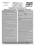
MMS Tote & Platform Lift
MMS-20
Service Manual
LIFT PRODUCTS INC
PO BOX 349
ELM GROVE WI 53122
262-521-5720 FAX 262-521-5725
Toll Free 877-543-8776
Model: MMS-20
S/N ________________________________
Customer____________________________
REGISTRATION INFORMATION
(To validate your warranty and receive updated service bulletins, please complete this form)
Date_______________
Model No.________________
How did you first hear of Lift Products?
____Magazine Ad (Specify which magazine)_____________________________________
____Recommended by a dealer (Name of Dealer)_________________________________
____Received information in the mail
____Internet
____Other (Please specify)___________________________________________________
What factors caused you to choose Lift Products?____________________________________
____________________________________________________________________________
____________________________________________________________________________
Describe how and where products are being used?____________________________________
____________________________________________________________________________
____________________________________________________________________________
Name of person completing this form______________________________________________
Title________________________________________________________________________
Company____________________________________________________________________
Street Address________________________________________________________________
City, State, Zip________________________________________________________________
Phone________________________ Fax No.________________________________________
Purchased From:
Name of Dealer_______________________________________________________________
Street Address________________________________________________________________
City, State, Zip________________________________________________________________
Phone No._____________________Fax No.________________________________________
Please fax this form to 262-521-5725.
CONTENTS
I
Nomenclature of Each Section
II
Attention
III
Operation Instructions
IV
Daily Care
V
Periodical Inspection
VI
How to Assemble
VII
Safety Instructions
VIII
Exploded Figure and Parts List
1
I
NOMENCLATURE OF EACH SECTION
1. Table
2. Lowering Valve
3. Foot Pedal (Pumping Pedal)
4. Drawer (Low Profile without Drawer
5. Brake
6. Chassis
7. Lift
8. Lowering Valve
9. Lower
10.Stopper
11.Foot Pedal (Pumping Pedal)
II
ATTENTION
1. Use it on a level paved road. If it is driven on a level road, the wheels are not
damaged and can be operated lightly.
2. Don’t overload it beyond the prescribed maximum load.
3. When putting a load on the table, don’t load it biased, for instance, on one side or at
the force end of the table.
2
III
OPERATION INSTRUCTIONS
IV
DAILY CARE
V
PERIODICAL INSPECTION
VI HOW TO ASSEMBLE
When assemble “Platform Stacker” do so securely, taking the following step.
When assembling it, two spanners 13 and two spanners 17 are required.
Clamping tools, such as monkey wrenches will do as well.
1. Raise (Lift) of the table.
• Tighten the lowering valve (by turning it clockwise), put down the foot pedal and work it. Then the table will lift up.
2. Lowering of the table.
• Loosen the lowering valve (by turning it counter-clockwise), and then the table
will lower down.
3. Lowering speed of the table can be adjusted according to the degree it is turned.
4. Range of lowering speed adjustment.
• In order to prevent abrupt lowering of the table when loading good, the truck is
provided with stopped. When the lowering speed is too quick or too slow, adjust
the position of this stopped.
1. If the load chain is corroded, it becomes weak and dangerous, so always lubricate it
by applying grease.
2. Unless oil leaks from the pump. It is not necessary to supply oil for about half a year
to one year.
3. Usually, when changing oil or replenishing oil, use L-HL68 Hydraulic oil (equivalent to
ISO VG68). If temperature is between -15°C -- -5°C, please use L-HL46 Hydraulic oil
(equivalent to ISO VG68).
1.
2.
3.
4.
Inspect the chain fixing nut for looseness.
Check whether the rotating parts are well lubricated or not.
Inspect the wheels for wear.
Inspect the screw in each part for looseness.
1. Take the assemblies from the carton box and disassemble them in order of (a), (b),
(c), (d), and (e) as follow:
Carton Box (a); Chassis (b); Handle (c); Table (d); Drawer (e); Bolt & Nut
3
Lay the handle on the floor as shown in the figure below.
2. Put the table into the handle.
CAUTION! Put it between the two rollers of the table
3. Attach the chain. Fasten the unit with the nut tightly.
4. After attaching the chain, invert the unit as shown in the Figure below.
5. Fasten the chassis with 4 bolts securely. Put the pin into the hole in the pump.
4
6. Erect the chassis and put it into the drawer.
VII
SAFETY INSTRUCTIONS
1.
Safety Rules
WARNING: Failure to obey the instructions and safety rules in this manual may result in death or serious injury.
1.1
Do Not Operate Unless:
1. You learn and practice the principles of safe machine operation contained in this
operating manual.
• Avoid hazardous situations.
• Always perform a pre-operation inspection.
• Always perform the function tests prior to use.
• Inspect the work place.
• Only use the machine as a material lift.
2. You read, understand and obey:
• Manufacturer’s instructions and safety rules.
• Employer’s safety rules and work site regulations.
• Applicable governmental regulations.
1.2
To Avoid Hazardous Situations
1. Fall Hazard
Do not use a personnel lifting platform or step.
2. Tip-Over Hazards
• Do not overload the winch stacker.
• Do not raise the load unless the machine is on a firm, level surface.
• Do not move the machine with a raised load, except for minor positioning.
• Do not tilt the machine back with a raised load.
• Do not operate the machine in strong or gusty winds.
• Prior to use, check the work area for drop-offs, holes, bumps, debris, unstable
surfaces or other possible hazardous conditions.
• Do not subject the machine to horizontal force by raising or lowering a fixed or
5
overhanging load.
3.
4.
5.
6.
7.
8.
9.
• User refers to prEN1005-3 for further guidance.
• If the load exceeds the actual operational capacity, the operator must be assisted
by one or more persons.
• The machine can be only used in the light environment of at least 50LUX.
Collision Hazards
• Do not lift if the load is not properly centered on the forks.
• Check the work area for overhead obstruction or other possible hazards.
• Do not stand under or allow personnel under the machine when the load is
raised.
• Do not lower the load unless the area below is clear of personnel and
obstructions.
Bodily Injury Hazards
• Do not grasp the cable.
• Keep hands and fingers away from pulleys, the carriage and other potential pinch
points.
• Recommended operators to wear safety shoes and gloves.
• Do not put the feet under the forks to avoid any damages when using the
machine.
Improper Use Hazard
• Never leave a machine unattended with a load.
• Unauthorized personnel may attempt to operate the machine without proper
instruction, creating an unsafe situation.
Damaged Machine Hazards
• Do not use a damaged or malfunctioning machine.
• Do not use a machine with a worn, frayed, kinked or damaged cable.
• Do not use a machine with less that 4 wraps of cable on the winch drum when
the carriage is fully lowered.
• If you see the red mark on the cable, at least 4 wraps are on the winch drum.
• Conduct a thorough pre-operation inspection prior to each use.
• Be sure that all decals are in place and legible.
• Maintain proper lubrication of the winch.
Crushing Hazard
• Do not release grasp on the winch handle until the brake is locked.
Lifting Hazard
• Use proper lifting techniques to load or tip the machine.
Other Items
• When pushing the machine on the rough floor the force will be bigger.
• To avoid overloading, the operating force will increase and reach to 400N when
reaching to the nominal load.
• Pay attention to the balance of the goods to avoid their turning over when lifting
them.
• Do pay attention to avoid the goods turn over towards the back when using the
machine on a slope.
6
VII
Exploded Figure and Parts List
7
LIFT TABLE SPARE PARTS LIST FOR MMS-20
NO
1
2
3
4
5
6
7
8
9
10
11
12
13
14
15
16
17
18
19
20
21
DESCRIPTION
Hand Rack
Nut
Washer
Nut
Bolt
Nut
Retain Pin
Bolt
Washer
Roller
Bearing
Roller Pin
Platform
Drawer
Pin
Retaining Ring
Retaining Ring
Bearing
Front Wheel
Chassis
Nut
QTY
1
2
2
2
4
4
4
4
4
4
4
4
1
1
2
4
4
4
2
1
2
NO
22
23
24
25
26
27
28
29
30
31
32
33
34
35
36
37
38
39
40
41
42
DESCRIPTION
Washer
Steering Wheel
Screw
Washer
Spring
Steel Ball
Bolt
O-Ring
Screw
Spring
Pin
Link Plate
Locating Plate
Spring
Screw
Locating Ring
Shaft
Revolving Ring
Pin
Chain Bolt
Chain
QTY
2
2
2
2
4
2
2
2
1
1
1
1
1
1
2
2
1
1
2
2
1
8
LIFT TABLE SPARE PARTS LIST FOR MMS-20
NO
43
44
45
46
47
48
49
50
51
52
53
54
55
56
57
58
59
60
61
62
63
DESCRIPTION
Chain Wheel Cover
Bearing
Chain Wheel
Pin
Retaining Ring
Chain Wheel Cover
Nut
Bolt
Piston Rod
Dustproof Ring
O-Ring
Retaining Ring
Internal Bush
Pump Rod
Internal Cylinder
Pump Spring Cover
Sealing Plate
Pump Spring
Locating Lug
Cylinder Pin
Valve Core
QTY
1
1
1
1
2
1
2
2
1
1
2
1
1
1
1
1
1
1
2
1
1
NO
64
65
66
67
68
69
70
71
72
73
74
75
76
77
78
79
80
81
82
DESCRIPTION
O-Ring
Pipe
External Cylinder
Pump Body
Dustproof Ring
O-Ring
Retaining Ring
Pump Bush
Oil Holder
Pin
Pump Base
Nut
Pin
Pump Pressure Roll
Bearing
Steel Ball
Bearing Bush
Bar
Rubber Bush
QTY
2
1
1
1
1
2
1
1
2
1
1
1
1
1
1
1
1
1
1
9