1
TK-3160
CIRCUIT DESCRIPTION
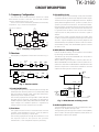
6) Tone Volume Fixed Circuit
This function generates a TONE signal sound even if the
AF volume of the transceiver is the minimum.
A TONE signal is sent through Q602 to the AF amplifier
when, in the FPU, “TONE Volume Fixed” is set to ON.
(3) MSK (Fleet Sync)
Fleet Sync utilizes 1200bps and 2400bps MSK signal is
output from pin 6 of IC601. And is routed to the VCO.
When encoding MSK, the microphone input signal is muted.
RECEIVE SIGNALING
IC601
AQUA
VOL
IC601
FM IF IC401
IC605
TA7368F
IC805 BEEP
CPU
IC602
IF Amp
SIGNAL
DTMF
IF Amp
AQUA
QT/DQT
TONE VOL FIXED
Q602
BEEPSW
Hi: ON
LOW: OFF
IC605
AF PA
IC805
LSDI
AN SQL
Q608
SW
SP
CLK,DATA,
STD,LOADN
+
SP-J
IC603
BPF & COMPALATER
CPU
HSDI
SP MUTE
SP
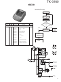
Fig. 5 AF amplifier and squelch
Output Level (mV)
[VOL Position vs Output Level]
(4) DTMF
The DTMF input signal from the IF IC (IC401) is amplified
by IC602 and goes to IC601, the DTMF decoder. The
decoded information is then processed by the CPU.
500
ON
25
Min
Q603,604,607
SW
2-TONE
OFF
Center
Max
Fig. 4 Tone volume fixed circuit
3. PLL Frequency Synthesizer
The PLL circuit generates the first local oscillator signal for
reception and the RF signal for transmission.
7) Squelch
Part of the AF signal from the IC enters the FM IC (IC401)
again, and the noise component is amplified and rectified
by a filter and an amplifier to produce a DC voltage
corresponding to the noise level.
The DC signal from the FM IC goes to the analog port of
the microprocessor (IC805). IC805 determines whether to
output sounds from the speaker by checking whether the
input voltage is higher or lower than the preset value.
To output sounds from the speaker, IC805 sends a high
signal to the SP MUTE line and turns IC605 on through
Q603,Q604,Q607 and Q608. (See Fig. 5)
8) Receive Signalling
(1) QT/DQT
The output signal from IF IC (IC401) enters the
microprocessor (IC805) through IC601. IC805 determines
whether the QT or DQT matches the preset value, and
controls the SP MUTE and the speaker output sounds
according to the squelch results.
(2) 2-TONE
Part of the received AF signal output from the AF amplifier
IC602, and then pass through an audio processor (IC601),
goes to the other AF amplifier IC603, is compared, and then
goes to IC805. IC805 checks whether 2-TONE data is
necessary. If it matches, IC805 carries out a specified
operation, such as turning the speaker on. (See Fig. 5)
8
1) PLL
The frequency step of the PLL circuit is 5 or 6.25kHz.
A 16.8MHz reference an oscillator signal is divided at IC1
by a fixed counter to produce oscillator (VCO) output signal
which is buffer amplified by Q9 then divided in IC1 by a
dual-module programmable counter. The divided signal is
compared in phase with the 5 or 6.25kHz reference signal
from the phase comparator in IC1. The output signal from
the phase comparator is filtered through a low-pass filter
and passed to the VCO to control the oscillator
frequency.(See Fig. 6)
2) VCO
The operating frequency is generated by Q6 in transmit
mode and Q5 in receive mode. The oscillator frequency is
controlled by applying the VCO control voltage, obtained
from the phase comparator, to the varactor diodes (D4 and
D7 in transmit mode and D3 and D9 in receive mode). The
RX pin is set high in receive mode causing Q8 and Q12 to
turn Q6 off and turn Q5 on.
The TX pin is set high in transmit mode. The outputs from
Q5 and Q6 are amplified by Q9 and sent to the RF amplifiers.