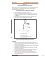
1
Service Manual
PG-08 Integrated Engine Control
System for GM 8.1L Engines
2008 Emission-Certified
Non-Adjustable
Natural Gas Fuel System
Revision 01
Limited Mechanical Warranty on New GM Powertrain Engines
Manufactured by Buck’s Engines
Used In Industrial Applications
Terms of Coverage: Uses
This warranty applies to the first retail purchaser and subsequent owners during the WARRANTY PERIOD for new GM Powertrain Engines
manufactured by Buck’s Engines (referred to as Engine) that are used in industrial applications.
Defects:
This warranty covers Engine REPAIRS to correct any warranted malfunction occurring during the WARRANTY PERIOD resulting from defects in material
or workmanship.
Repairs:
To obtain warranty repairs, you must request the needed repairs within the WARRANTY PERIOD from an authorized Buck’s Engines service outlet. Repairs
covered by this warranty must be pre-approved by a Buck’s Engines authorized representative. Only new genuine parts or remanufactured parts or
components supplied or approved by Buck’s Engines will be used. Buck’s Engines may, at its discretion, replace rather than repair
components. A reasonable time must be allowed to perform the warranty repair after taking the Engine to the authorized service outlet. Repairs will be
performed during normal business hours.
This Warranty Does Not Cover:
Repairs Due to Accidents, Misuse, Storage Damage, Negligence or Certain Modifications
Buck’s Engines is not responsible for repairs due to improper calibration of spark, fuel, and cooling systems; misuse, negligence, accident, alterations,
or applications not approved by Buck’s Engines; lack of performance of required maintenance services as recommended by Buck’s Engines or improper
installation; or the failure to use fuel, oil, lubricants and coolant meeting Buck’s Engines recommended specifications. Performance of the required
maintenance services and use of proper fuel, oil, lubricants and coolant are the responsibility of the owner. See the Owner’s Manual for full details.
Engine Removal and Reinstallation:
Reasonable labor costs (Maximum of 4 Hours) for Engine removal and reinstallation when necessary to make a warranty repair are covered by this
warranty.
Maintenance Items:
This warranty does not cover the replacement of maintenance items (such as oil, spark plugs, ignition points, PCV valves and filters) made in
connection with normal maintenance service.
Limitations:
Incidental or Consequential Damages
This warranty does not cover any economic loss, including without limitation, loss of use of the Engine or equipment, costs of substitute or
replacement equipment, loss of time, inconvenience, or any other cost or expense resulting from a defect covered by this warranty.
Warranty Period:
The WARRANTY PERIOD begins on the date the Engine is delivered to the first retail purchaser or put into service, whichever occurs first. In any
event, the WARRANTY PERIOD will commence no later than one year after the Engine’s model year production ends. The WARRANTY
PERIOD will end at the time limits shown below:
Warranty Limitations (Whichever Occurs First)
ITEM
Engine and Internal Moving Parts
Electrical Components
Cooling System Components
MONTHS
36
3
6
ENGINE HOURS
3,500 Hours
1,000 Hours
2,000 Hours
No Other Warranty:
THIS LIMITED WARRANTY IS THE ONLY WARRANTY APPLICABLE TO THESE ENGINES. BUCK’S ENGINES MAKES NO OTHER
WARRANTIES EXPRESS OR IMPLIED.
September 2010
UE Powertrain LP, d/b/a Buck’s Engines - 20 N. McCormick - Oklahoma City, Oklahoma 73127
WARNING—DANGER OF DEATH OR PERSONAL INJURY
WARNING—FOLLOW INSTRUCTIONS
Read this entire manual and all other publications pertaining to the work to be performed
before installing, operating, or servicing this equipment. Practice all plant and safety
instructions and precautions. Failure to follow instructions can cause personal injury and/or
property damage.
WARNING—OVERSPEED PROTECTION
The engine, turbine, or other type of prime mover should be equipped with an overspeed
shutdown device to protect against runaway or damage to the prime mover with possible
personal injury, loss of life, or property damage.
The overspeed shutdown device must be totally independent of the prime mover control
system. An overtemperature or overpressure shutdown device may also be needed for
safety, as appropriate.
WARNING—PROPER USE
Any unauthorized modifications to or use of this equipment outside its specified
mechanical, electrical, or other operating limits may cause personal injury and/or property
damage, including damage to the equipment. Any such unauthorized modifications: (i)
constitute "misuse" and/or "negligence" within the meaning of the product warranty
thereby excluding warranty coverage for any resulting damage, and (ii) invalidate product
certifications or listings.
CAUTION—POSSIBLE DAMAGE TO EQUIPMENT OR PROPERTY
CAUTION—BATTERY CHARGING
To prevent damage to a control system that uses an alternator or battery-charging device, make
sure the charging device is turned off before disconnecting the battery from the system.
CAUTION—ELECTROSTATIC DISCHARGE
Electronic controls contain static-sensitive parts. Observe the following precautions to
prevent damage to these parts.
•
Discharge body static before handling the control (with power to the control turned off,
contact a grounded surface and maintain contact while handling the control).
•
Avoid all plastic, vinyl, and Styrofoam (except antistatic versions) around printed circuit
boards.
•
Do not touch the components or conductors on a printed circuit board with your hands
or with conductive devices.
•
•
•
IMPORTANT DEFINITIONS
A WARNING indicates a potentially hazardous situation which, if not avoided, could result in
death or serious injury.
A CAUTION indicates a potentially hazardous situation which, if not avoided, could result in
damage to equipment or property.
A NOTE provides other helpful information that does not fall under the warning or caution
categories.
Buck's Engines reserves the right to update any portion of this publication at any time. Information
provided by Buck's Engines is believed to be correct and reliable. However, no responsibility is
assumed by Buck's Engines unless otherwise expressly undertaken.
Manual 36548
PG-08 Engine Control System for GM 8.1L
Contents
REGULATORY COMPLIANCE ....................................................................... 6
EPA / CARB Emissions Certification ...................................................................... 6
North American Compliance................................................................................... 6
ELECTROSTATIC DISCHARGE AWARENESS .................................................. 7
CHAPTER 1. SYSTEM OVERVIEW ................................................................ 8
PG-08 General Description..................................................................................... 8
PG-08 System Components ................................................................................. 10
Key Components .......................................................................................... 10
PG-08 System Features ....................................................................................... 10
Natural Gas Fuel System Operation ..................................................................... 12
PG-08 Electric Fuel Lock-Off ........................................................................ 12
Fuel Filter ...................................................................................................... 13
Maxitrol 210DZ Pressure Regulator ............................................................. 14
D100 Mixer.................................................................................................... 15
Electronic Throttle System .................................................................................... 16
PG-08 Electronic Throttle ............................................................................. 16
Ignition System ..................................................................................................... 18
General Motors (GM) Coil Near Plug Ignition System .................................. 18
Exhaust System .................................................................................................... 20
Catalytic Converter ....................................................................................... 20
SECM ................................................................................................................... 22
Fuel Management ......................................................................................... 22
Speed Management...................................................................................... 23
SECM / Sensors ........................................................................................... 24
Analog Inputs ................................................................................................ 24
Frequency/Position Inputs ............................................................................ 24
Digital Inputs ................................................................................................. 25
Outputs ......................................................................................................... 25
CHAPTER 2. SPECIFICATIONS ................................................................... 26
Fuel System Requirements .................................................................................. 26
Environmental / Electrical Specifications .............................................................. 26
210DZ Pressure Regulator Specifications ........................................................... 26
D100 Mixer Specifications .................................................................................... 27
Electronic Throttle System Specifications ............................................................ 27
SECM Specifications ............................................................................................ 27
Fuel Trim Valve (FTV) Specifications ................................................................... 28
Ignition System Specifications .............................................................................. 28
Chapter 3. Recommended Maintenance .............................................................. 29
Maintenance Tests & Inspections ......................................................................... 29
Test Fuel System for Leaks .......................................................................... 29
Inspect Engine for Fluid Leaks ..................................................................... 29
Inspect Vacuum Lines and Fittings ............................................................... 29
Inspect Electrical System .............................................................................. 29
Inspect Coolant Hoses .................................................................................. 30
Inspect Battery System ................................................................................. 30
Inspect Ignition System ................................................................................. 30
Replace Spark Plugs .................................................................................... 30
Testing Fuel Lock-off Operation ................................................................... 30
Pressure Regulator Inspection ..................................................................... 30
Fuel Trim Valve Inspection (FTV) ................................................................. 31
Inspect Mixer Assembly ................................................................................ 31
Inspect for Intake Leaks................................................................................ 31
Inspect Throttle Assembly ............................................................................ 31
Buck’s Engines
3
Manual 36548
PG-08 Engine Control System for GM 8.1L
Checking the TMAP Sensor ......................................................................... 31
Inspect Engine for Exhaust Leaks ................................................................ 31
Maintenance Schedule ......................................................................................... 32
CHAPTER 4. INSTALLATION PROCEDURES ................................................. 34
Removal and Installation of 210DZ Regulator ...................................................... 35
Removal and Installation of D100 Mixer ............................................................... 36
CHAPTER 5. TESTS AND ADJUSTMENTS .................................................... 38
210DZ Regulator Service Testing......................................................................... 38
Connection of PG-08 Service Tool ....................................................................... 40
Chapter 6. Basic Troubleshooting ........................................................................ 41
Preliminary Checks ............................................................................................... 41
Basic Troubleshooting .......................................................................................... 42
Intermittents .................................................................................................. 42
Surges and/or Stumbles ............................................................................... 43
Engine Cranking but Will Not Start / Difficult to Start .................................... 44
Lack of Power, Slow to Respond / Poor High Speed Performance /
Hesitation During Acceleration...................................................................... 46
Detonation / Spark Knock ............................................................................. 48
Backfire ......................................................................................................... 49
Dieseling, Run-on ......................................................................................... 49
Rough, Unstable, Incorrect Idle, or Stalling .................................................. 50
Cuts Out, Misses .......................................................................................... 52
Poor Fuel Economy / Excessive Fuel Consumption Natural Gas Exhaust
Smell ............................................................................................................. 53
High Idle Speed ............................................................................................ 54
Excessive Exhaust Emissions or Odors ....................................................... 55
Diagnostic Aids for Rich / Lean Operation .................................................... 56
Chart T-1 Restricted Exhaust System Check ............................................... 57
CHAPTER 7. ADVANCED DIAGNOSTICS ...................................................... 58
Reading Diagnostic Fault Codes .......................................................................... 58
Displaying and Clearing Fault Codes (DFC) from SECM Memory ....................... 58
Fault Action Descriptions .............................................................................. 59
Fault List Definitions...................................................................................... 60
Table 1. Fault List Definitions........................................................................ 60
Table 2. Diagnostic Fault Codes (Flash Codes) ........................................... 67
CHAPTER 8. PARTS DESCRIPTION............................................................. 81
Fuel System Components .................................................................................... 81
Maxitrol 210DZ Regulator ..................................................................................... 82
Buck’s Engines
4
Manual 36548
PG-08 Engine Control System for GM 8.1L
List of Figures
Figure 1. PG-08 System for GM 8.1L Natural Gas Engines ................................... 8
Figure 2. PG-08 Closed Loop NG Fuel System...................................................... 9
Figure 3. Maxitrol 210DZ Regulator...................................................................... 14
Figure 4. D100 Mixer ............................................................................................ 15
Figure 5. D100 Mixer Attached to Throttle Body................................................... 15
Figure 8. Bosch Electronic Throttle Body ............................................................. 16
Figure 9. Throttle Body Assembly Exploded View ................................................ 17
Figure 10. HEGO (O2) Sensor ............................................................................. 20
Figure 11. Throttle Position Sensor (TPS) on DV-E5 Throttle .............................. 23
Figure 15. 210DZ Regulator ................................................................................. 35
Figure 16. D100 Mixer Installed on Engine........................................................... 36
Figure 17. Wire Harness Connector on Throttle Body.......................................... 37
Figure 19. Regulator Pressure Test Connections ................................................ 38
Figure 21. KVaser Communication Adapter ......................................................... 40
Figure 22. Crypt Token Installed on Laptop.......................................................... 40
Figure 23. Opening the Service Tool Display ....................................................... 40
Figure 26. Installing Exhaust Backpressure Tester .............................................. 57
Buck’s Engines
5
Manual 36548
PG-08 Engine Control System for GM 8.1L
Regulatory Compliance
EPA / CARB Emissions Certification
When properly applied and calibrated, Buck's Engines' PG-08 control system
meets EPA 2008 stationary emission standards for rich-burn natural gas (40 CFR
Part 60) when operating properly with an approved three-way catalyst. The
emissions test is based on the ISO 8178 type D2 steady-state test cycle. The
emission standards, including appropriate deterioration factors over the useful life
of the system, are as follows:
When operating on natural gas, 8000 hour deteriorated emissions shall be less
than or equal to:
NMHC:
1.0 g/hp-hr
CO:
4.0 g/hp-hr
NOx:
2.0 g/hp-hr
The PG-08 control system complies with New Source Performance Standards
(NSPS) and National Emission Standards for Hazardous Air Pollutants
(NESHAP) proposed by the EPA. These standards are effective in 2008 for
stationary spark-ignited engines.
As defined in applicable regulations, the engine control system is designed to
maintain emissions compliance for ten (10) years or 8000 hours, whichever
occurs first, provided appropriate maintenance is performed as defined in the
service manual for the system. Maintenance intervals shall be defined and
approved by the regulating body. Component warranty shall comply with
regulatory requirements (40 CFR Part 1048.120) for all emission related
components. Warranty for non-critical emissions components will be as defined in
the individual purchase agreement.
North American Compliance
The 210DZ regulator is UL listed per Category MIMV2.
The 210DZ regulator has tamper-resistant features approved by the California Air
Resources Board (CARB) when used with commercial grade fuel.
Buck’s Engines
6
Manual 36548
PG-08 Engine Control System for GM 8.1L
Electrostatic Discharge Awareness
All electronic equipment is static-sensitive, some components more than others.
To protect these components from static damage, you must take special
precautions to minimize or eliminate electrostatic discharges.
Follow these precautions when working with or near the control.
1.
Before doing maintenance on the electronic control, discharge the static
electricity on your body to ground by touching and holding a grounded metal
object (pipes, cabinets, equipment, etc.).
2.
Avoid the build-up of static electricity on your body by not wearing clothing
made of synthetic materials. Wear cotton or cotton-blend materials as much
as possible because these do not store static electric charges as much as
synthetics.
3.
Keep plastic, vinyl, and Styrofoam materials (such as plastic or Styrofoam
cups, cup holders, cigarette packages, cellophane wrappers, vinyl books or
folders, plastic bottles, and plastic ash trays) away from the control, the
modules, and the work area as much as possible.
Buck’s Engines
7
Manual 36548
PG-08 Engine Control System for GM 8.1L
Chapter 1.
System Overview
PG-08 General Description
Buck's Engines' emission-certified PG-08 control system provides a complete,
fully integrated engine management system that helps OEMs and packagers
comply with New Source Performance Standards (NSPS) proposed by the
Environmental Protection Agency (EPA). These standards are effective in 2008
for stationary spark-ignited engines.
The control system is applicable to naturally aspirated engines ranging in size
from 1.6L to 8.1L (25 to 220 HP [18.64 to164 kW] with up to 8 cylinders running on
natural gas in stationary industrial applications.
It provides accurate, reliable, and durable control of fuel, spark, and air over the
service life of the engine in the extreme operating environment found in heavyduty, under hood, on-engine electronic controls.
PG-08 is a closed loop system utilizing a catalytic converter to reduce the
emission level in the exhaust gas. In order to obtain maximum effect from the
catalyst, an accurate control of the air fuel ratio is required. A small engine control
module (SECM) uses two heated exhaust gas oxygen sensors (HEGO) in the
exhaust system to monitor exhaust gas content. One HEGO is installed in front of
the catalytic converter and one is installed after the catalytic converter.
Figure 1. PG-08 System for GM 8.1L Natural Gas Engines
The SECM makes any necessary corrections to the air fuel ratio by controlling the
inlet fuel pressure to the air/fuel mixer by controlling the position of the L-Series
fuel trim valve. Closing the valve leans the air/fuel mixture and opening the valve
enriches the air/fuel mixture. To calculate any necessary corrections to the air
fuel ratio, the SECM uses a number of different sensors to gain information about
the engine’s performance. Engine speed is monitored by the SECM through a
Buck’s Engines
8
Manual 36548
PG-08 Engine Control System for GM 8.1L
variable reluctance (VR) or Hall Effect sensor. Intake manifold air temperature
and absolute pressure are monitored with a TMAP sensor. PG-08 is a drive-bywire (DBW) system connecting the accelerator pedal to the electronic throttle
through the electrical harness; mechanical cables are not used. A throttle position
sensor (TPS) monitors throttle position in relation to the accelerator pedal position
sensor (APP) command. Even engine coolant temperature and adequate oil
pressure are monitored by the SECM. The SECM controller has full adaptive
learning capabilities, allowing it to adapt control function as operating conditions
change. Factors such as ambient temperature, fuel variations, ignition component
wear, clogged air filter, and other operating variables are compensated.
PG-08 Closed Loop Natural Gas Fuel System
Figure 2. PG-08 Closed Loop NG Fuel System
Buck’s Engines
9
Manual 36548
PG-08 Engine Control System for GM 8.1L
PG-08 System Components
The PG-08 control system provides electronic control to the following subsystems
on stationary industrial engines:
• Fuel delivery system
•
Spark-ignition control system
•
Air throttle
•
Sensors/Switches/Speed inputs
Key Components
The PG-08 system functions primarily on engine components that affect engine
emissions and performance. These key components include the following:
• Engine/Combustion chamber design
• Intake/Exhaust valve configuration, timing and lift
• Intake/Exhaust manifold design
• Catalytic converter and exhaust system
• Throttle body
• Air intake and air filter
• Gaseous fuel mixer
• Gaseous fuel pressure regulator
• Fuel trim valve
• Small engine control module (SECM), firmware and calibration
• Fuel system sensors and actuators
• Ignition system including spark plugs, cables, coils and drivers
PG-08 System Features
The PG-08 system uses an advanced speed-density control strategy for fuel,
spark, and air throttle control. Key features include the following.
•
Speed-load spark control with tables for dwell, timing, and fuel type
•
Speed-load throttle control with table for maximum TPS limiting
•
Closed-loop fuel control with two oxygen sensors (one installed pre
catalyst and one installed post catalyst). The pre-catalyst oxygen
sensor includes adaptive learn to compensate for fuel or component
drift. The post-catalyst oxygen sensor includes adaptive learn to
compensate the pre-catalyst oxygen sensor setting for pre-catalyst
oxygen sensor drift and catalyst aging. The pre-catalyst oxygen
sensor function includes parameters for transport delay, O2 set point,
excursion rich/lean, jump back rich/lean, and perturbation.
•
Min/max governing
•
All-speed isochronous governing
•
Fixed-speed isochronous governing with three switch-selectable
speeds
•
Fuel enrichment and spark timing modifiers for temperature and fuel type
•
Transient fuel enrichment based on rate of change of TPS
•
Input sensor selection and calibration
Buck’s Engines
10
Manual 36548
PG-08 Engine Control System for GM 8.1L
•
Auxiliary device control for fuel pump, fuel lock-off solenoid, MIL,
interlocks, engine speed limiting, etc.
•
CANBus data transfer for speed, torque, etc.
Other System Features Include:
Tamper-Resistance
(Applications Using Commercial Grade Fuel)
Special tools, equipment, knowledge, and authorization are required to effect any
changes to the PG-08 system, thereby preventing unauthorized personnel from
making adjustments that will affect performance or emissions.
Diagnostics
PG-08 is capable of monitoring and diagnosing problems and faults within the
system. These include all sensor input hardware, control output hardware, and
control functions such as closed-loop fuel control limits and adaptive learn limits.
Upon detecting a fault condition, the system notifies the operator by illuminating
the MIL and activating the appropriate fault action. The action required by each
fault shall be programmable by the OEM at the time the engine is calibrated.
Diagnostic information can be communicated through both the Service Tool
interface and the MIL lamp. With the MIL lamp, it is possible to generate a string
of flashing codes that correspond to the fault type. These diagnostics are
generated only when the engine is not running and the operator initiates a
diagnostic request sequence such as repeated actuations of the pedal within a
short period of time following reset.
Service Tool
A scan tool/monitoring device is available to monitor system operation and assist
in diagnosis of system faults This device monitors all sensor inputs, control
outputs, and diagnostic functions in sufficient detail through a single access point
to the SECM to allow a qualified service technician to maintain the system. This
MotoService software (licensed by MotoTron Corporation) is secure and requires
a crypt-token USB device to allow access to information.
NOTE
It is the responsibility of the customer to consult with Buck's Engines
regarding the selection or specification of any components that impact
emissions, performance, or durability.
Buck’s Engines
11
Manual 36548
PG-08 Engine Control System for GM 8.1L
Natural Gas Fuel System Operation
The principles outlined below describe the operation of PG-08 on a natural gas
fuel system.
A natural gas fuel system consists of the following components:
•
Fuel filter (supplied by customer)
•
Electric fuel vapor lock-off solenoid valve
•
Fuel pressure regulator
•
Twin orifice fuel trim valves
•
Gas/air mixer
•
Miscellaneous hoses and fittings
Fuel passes through a lock-off valve, and is then regulated down to the
appropriate pressure to supply the mixer. The regulator controls the fuel pressure
to the gas/air mixer. In some cases, a primary regulator is required to bring the
supply pressure down to 8-15 inH2O before the PG-08 fuel pressure regulator
stage.
L-Series Fuel Trim Valve
The key to meeting emissions requirements when operating on natural gas is the
L-Series trim valve in the fuel system. The L-Series fuel trim valve used in the
PG-08 system is configured as a positioner and will go to a position that is
commanded via a pulse-width modulated signal. The L-Series trim valve controls
fuel delivery by providing a restriction in the fuel line prior to entering the mixer.
The valve controls the restriction by moving to a commanded position based on
feedback from the SECM.
SECM
The Small Engine Control Module (SECM) controls the natural gas lock-off
solenoid valve and the FTV. The lock-off valve is energized when fueling with
natural gas and the engine is turning. FTV commands will be altered by the
SECM in order to maintain a stoichiometric air-fuel ratio. Commands are based
primarily on feedback from the exhaust gas oxygen sensor.
PG-08 Electric Fuel Lock-Off
The fuel lock-off is a safety shutoff valve, normally held closed by spring
pressure, which is operated by an electric solenoid and prevents fuel flow to the
regulator when the engine is not in operation.
In the PG-08 design, power is supplied to the fuel lock-off via the main power
relay with the SECM controlling the lock-off ground (earth) connection. The lockoff remains in a normally closed (NC) position until the key switch is activated.
This supplies power to the lock-off and the SECM, but will not open the lock-off
via the main power relay until the SECM provides the lock-off ground connection.
This design gives the SECM full control of the lock-off while providing additional
safety by closing the fuel lock-off in the unlikely event of a power failure, wiring
failure or module failure.
Buck’s Engines
12
Manual 36548
PG-08 Engine Control System for GM 8.1L
When the fuel supply service valve is opened, natural gas flows through the
service line to the fuel lock-off. Natural gas enters the lock-off through the inlet
port and stops with the lock-off in the normally closed position. When the engine
is cranked over the main power relay applies power to the lock-off and the SECM
provides the lock-off ground causing current to flow through the windings of the
solenoid creating a magnetic field. The strength of this magnetic field is sufficient
to lift the lock-off valve off of its seat against spring pressure. When the valve is
open natural gas, at line pressure, flows through the lock-off outlet to the
pressure regulator. A stall safety shutoff feature is built into the SECM to close
the lock-off in case of a stall condition. The SECM monitors three engine states:
Crank, when the crankshaft position sensor detects any engine revolutions; Stall,
when the key is in the ON position but the crankshaft position sensor detects no
engine revolutions; and the Run state, when the engine reaches pre-idle rpm.
When an operator turns on the key switch the lock-off is opened, but if the
operator fails to crank the engine the SECM will close the lock-off after
approximately 5 seconds.
Fuel Filter
A fuel filter should be placed in the fuel line upstream from the fuel lock-off. The
fuel filter protects fuel system components from particulates and other
contaminates that may be present in the fuel.
NOTE
For system durability a fuel filter should be installed upstream of the
lock-off. The filter should be 10 micron or better at 99% efficiency.
Failure to use a filter may result in reduced system performance and
durability.
Buck’s Engines
13
Manual 36548
PG-08 Engine Control System for GM 8.1L
Maxitrol 210DZ Pressure Regulator
The pressure regulator receives gaseous natural gas from the supply line (8-15
inH20) [37.3–76.7 mbar]). It drops the pressure and provides vapor phase natural
gas at a regulated outlet pressure to the trim valve. The outlet pressure of the
regulator will be approximately equal to the pressure of the air entering the venturi
mixer.
Figure 3. Maxitrol 210DZ Regulator
Regulator Operation
Natural gas, at line pressure, enters the 210DZ through the fuel inlet port.
The regulating valve is at a fixed position that is determined by the setting of the
screw on top of the regulator when no gas is flowing. When the fuel lock-off is
opened fuel will flow into the inlet and straight through the regulator. If there is no
fuel demand the outlet pressure will increase, causing a force imbalance on the
valve/diaphragm that will close the valve. When the engine is running the valve
will open to maintain the outlet pressure at the setting commanded by the system.
The valve will open wider for higher fuel flow demands and will close for lower
fuel flow demands.
Buck’s Engines
14
Manual 36548
PG-08 Engine Control System for GM 8.1L
D100 Mixer
The mixer is installed above the throttle body and meters gaseous fuel into the
airstream at a rate that is proportional to the volumetric flow rate of air. The ratio
between volumetric airflow and volumetric fuel flow is controlled by the size of the
metering orifices inside the venturi and biased by the restriction in the fuel supply
line provided by the L-Series trim valve. Fuel flow must be metered accurately
over the full range of airflows. Pressure drop across the mixer air valve must be
minimized to assure maximum power output from the engine.
Figure 4. D100 Mixer
D100 Venturi Mixer Operation
Vapor natural gas fuel is supplied to the D100 mixer by the Maxitrol 210DZ
pressure regulator. When air enters the mixer the pressure will drop at the throat
of the mixer. This reduction in air pressure creates a pressure imbalance across
the fuel metering orifices. The fuel on one side of the orifices is at a higher
pressure than the air on the other side and as a result, fuel will flow across the
orifices into the airstream. The amount of fuel flow depends on the fuel pressure
at the orifices and the size of the orifices. The air/fuel mixture then travels past
the throttle, through the intake manifold and into the engine cylinders where it is
compressed, ignited and burned.
Figure 5. D100 Mixer Attached to Throttle Body
Buck’s Engines
15
Manual 36548
PG-08 Engine Control System for GM 8.1L
Electronic Throttle System
PG-08 Electronic Throttle
Conventional throttle systems rely on a mechanical linkage to control the throttle
valve. To meet fluctuating engine demands a conventional system will typically
include a throttle valve actuator designed to readjust the throttle opening in
response to engine demand, together with an idle control actuator or idle air
bypass valve.
In contrast, the PG-08 system uses electronic throttle control (ETC). The SECM
controls the throttle valve based on engine RPM, engine load, and information
received from the speed input device.
The PG-08 system uses a Bosch electronic throttle body DV-E5 in the following
sizes:
(a)
(b)
(c)
(d)
32mm
40mm
60mm
68mm
for 1.6L and 2.4L engines
for 3.0L and 4.3L engines
for 5.7L engines
for 8.1L engines
The DV-E5 is a single unit assembly, which includes the throttle valve, throttlevalve actuator (DC motor), and two throttle position sensors (TPS). The SECM
calculates the correct throttle valve opening that corresponds to the engine’s
demand, makes any adjustments needed
for adaptation to the engine’s current
operating conditions and then generates a
corresponding electrical (driver) signal to
the throttle-valve actuator.
Figure 8. Bosch Electronic Throttle
Body
Buck’s Engines
16
Manual 36548
PG-08 Engine Control System for GM 8.1L
The PG-08 system uses a dual TPS design (TPS1 and TPS2). The SECM
continuously checks and monitors all sensors and calculations that effect throttle
valve position whenever the engine is running. If any malfunctions are
encountered, the SECM’s initial response is to revert to redundant sensors and
calculated data. If no redundant signal is available or calculated data cannot solve
the malfunction, the SECM will drive the system into one of its limp modes or shut
the engine down, storing the appropriate fault information in the SECM.
Throttle Plate
Gear Drive
DC Drive Motor
Picture courtesy of Robert Bosch GmbH
Figure 9. Throttle Body Assembly Exploded View
Buck’s Engines
17
Manual 36548
PG-08 Engine Control System for GM 8.1L
Ignition System
Spark-ignited engines require accurate control of spark timing and spark energy
for efficient combustion. The PG-08 ignition system provides this control. The
system consists of the following components:
•
SECM
•
Ignition coils
•
Crankshaft position sensor
•
Crankshaft timing wheel
•
Camshaft position sensor
•
Camshaft timing wheel
•
Spark plugs
The SECM, through use of embedded control algorithms and calibration
variables, determines the proper time to start energizing the coil and fire the
spark plug. This requires accurate crank/camshaft position information, an engine
speed calculation, coil energy information, and target spark timing. The SECM
controls spark energy (dwell time) and spark discharge timing.
General Motors (GM) Coil Near Plug Ignition System
The GM 8.1L engine has a coil near plug ignition system. The engine comes
equipped with eight coils (one per cylinder) that are mounted near each cylinder.
A high tension ignition wire connects the output of each coil to the spark plug in
each cylinder.
The coils provided with the GM 8.1L engine provide a control interface that allows
external control modules to control engine timing and dwell. When the SECM
sends a 5-volt signal to the control interface, the coil control module begins
charging the coil. When the SECM signal returns to the ground state, the coil
discharges into the spark plug. In this way, the amount of time the SECM signal is
in the high state determines the coil dwell. The moment that the signal returns to
the ground state determines when the spark plug fires.
The SECM uses the crankshaft position sensor to determine the ignition timing,
so timing adjustments cannot be made.
IGNITION SYSTEM COMPONENTS
In a coil near plug ignition system, crankshaft and camshaft position sensors
generate a basic timing signal by reading notches on the crankshaft, flywheel, or
harmonic balancer and camshaft.
The crank and cam sensor signals go to the small engine control module
(SECM), where they are used to determine firing order and turn the individual
ignition coils on and off.
The operation of the ignition system is essentially the same as any other ignition
system. The coil has a low primary resistance (0.4 to 0.6 ohms) and steps up the
primary system voltage from 12 volts to as much as 40,000 volts to produce a
Buck’s Engines
18
Manual 36548
PG-08 Engine Control System for GM 8.1L
spark for the spark plug. Resistor spark plugs are generally used to suppress
electromagnetic interference (EMI).
MISFIRES
Common ignition system ailments include misfiring, hard starting, or a no start.
Spark plugs can still be fouled by oil or fuel deposits, as well as pre-ignition and
detonation.
If the crankshaft or camshaft position sensors fail, the loss of the basic timing
signal will prevent the system from generating a spark and the engine will not
start or run. A failed driver circuit within the SECM will also prevent proper ignition
system operation.
It is important to remember that ignition misfire can also be caused by other
factors such as worn or fouled spark plugs, loose or damaged coil connector or
terminals, low fuel pressure, intake vacuum leaks, loss of compression in a
cylinder, or even contaminated fuel. These other possibilities should all be ruled
out before coils are replaced.
A SECM controlled engine that cranks but fails to start, in many cases, will often
have a problem in the crankshaft or camshaft position sensor circuits. Loss of
sensor signals may prevent the SECM from properly synchronizing, thereby
preventing the engine from starting and running.
IGNITION SYSTEM CHECKS
The ignition coils can be tested with an ohmmeter. Measure primary and
secondary resistance and compare to specifications. If resistance is out of
specifications, the coil is bad and needs to be replaced.
Also, pay close attention to the tube that wraps around the spark plug. Cracks
can allow voltage to jump to ground causing a misfire. The spark plug terminal
should also fit tightly.
If a coil tests bad and is replaced, cleaning the connector and wiring harness
terminals of the coil can often avoid future problems. Corrosion at either place
can cause intermittent operation and loss of continuity, which may contribute to
component failure. Applying dielectric grease to these connections can help
prevent corrosion and assure a good electrical connection.
Buck’s Engines
19
Manual 36548
PG-08 Engine Control System for GM 8.1L
Exhaust System
Heated Exhaust Gas Oxygen Sensors (HEGO)
The PG-08 system utilizes two HEGO (O2) sensors. One sensor is a pre-catalyst
sensor that detects the amount of oxygen in the exhaust stream and is considered
the primary control point. Based upon the O2 sensor feedback, the PG-08 system
supplies a stoichiometric air-fuel ratio to the catalytic converter. The catalytic
converter then reduces emissions to the required levels. The second sensor is a
post-catalyst sensor that detects the amount of oxygen after the catalyst. This
sensor is used as a secondary control point to adjust the pre-catalyst setpoint to
ensure proper catalyst conversion efficiency.
Once a HEGO sensor reaches approximately
600°F (316°C), it becomes electrically active. The
concentration of oxygen in the exhaust stream
determines the voltage produced. If the engine is
running rich, little oxygen will be present in the
exhaust and voltage output will be relatively high.
Conversely, in a lean situation, more oxygen will
be present and a smaller electrical potential will be
noticed.
Figure 10. HEGO (O2)
Sensor
In order for the sensor to become active and create an electrical signal below
600°F (316°C) a heated element is added to the sensor housing. Two wires
provide the necessary 12 Vdc and ground signal for the heater element. A fourth
wire provides an independent ground for the sensor. The pre-catalyst sensor
heater is powered by the main power relay and is always powered. The postcatalyst sensor heater is powered from an additional relay that is controlled by the
SECM. This relay is only energized when the SECM calculates that water
condensation in the exhaust system and catalytic converter prior to the sensor
should be evaporated. This is to avoid thermal shock of the sensor that could
prematurely fail the sensor.
The HEGO stoichiometric air-fuel ratio voltage target is approximately 500 mV and
changes slightly as a function of speed and load. When the pre-catalyst HEGO
sensor sends a voltage signal less than 450 mV the SECM interprets the air-fuel
mixture as lean. The SECM then decreases the PWM duty cycle sent to the fuel
trim valves in order to increase the fuel pressure to the mixer inlet; thus richening
air-fuel mixture. The opposite is true if the SECM receives a voltage signal above
450 mV from the HEGO. The air-fuel mixture would then be interpreted as being
too rich and the SECM would increase the duty cycle of the trim valves.
CAUTION
The HEGO sensors are calibrated to work with the PG-08 control
system. Use of alternate sensors may impact performance and the
ability of the system to diagnose rich and lean conditions.
Catalytic Converter
In order to meet 2008 emission requirements a 3-way catalyst is necessary.
The PG-08 control system monitors the exhaust stream pre and post catalyst and
uses this information to control the air-fuel mixture. By using the signals from the
HEGOs, the SECM can increase or decrease the amount of oxygen in the
Buck’s Engines
20
Manual 36548
PG-08 Engine Control System for GM 8.1L
exhaust by modulating the FTV and adjusting the air-fuel ratio. This control
scheme allows the SECM to make sure that the engine is running at the correct
air to fuel ratio so that the catalyst can perform as required to meet the emissions
certification.
Buck’s Engines
21
Manual 36548
PG-08 Engine Control System for GM 8.1L
SECM
The Small Engine Control Module (SECM) controller has full authority over spark,
fuel and air. Utilizing a Freescale micro controller, the
SECM has 48 pins of I/O and is fully waterproof and
shock hardened. To optimize engine performance
and drivability, the SECM uses several sensors for
closed loop feedback information. These sensors are
used by the SECM for closed loop control in three
main categories:
•
Fuel Management
•
Load/Speed Management
•
Ignition Management
The SECM monitors system parameters and stores any out of range conditions
or malfunctions as faults in SECM memory. Engine run hours are also stored in
memory. Stored fault codes can be displayed on the Malfunction Indicator Light
(MIL) as flash codes or read by the PG-08 Service Tool software through a CAN
(Controller Area Network) communication link.
Constant battery power (12 Vdc) is supplied through the fuse block to the SECM
and the main power relays. Upon detecting a key-switch ON input, the SECM will
fully power up and energize the main power relays. The energized main power
relays supply 12 Vdc power to the heated element of the oxygen sensors, fuel
lock-off, fuel trim valve (FTV), crank sensor, cam sensor, and the ignition coils.
The SECM supplies voltage to the electronic throttle actuator, oil pressure switch,
fuel temperature sensor, and the coolant temperature sensor. Transducer or
sensor power (+ 5 Vdc) is regulated by the SECM and supplied to the manifold
temperature/air pressure (TMAP) sensor, throttle position sensor (TPS), and the
accelerator pedal position sensors (APP1 & APP2). The SECM provides a
transducer ground for all the sensors, and a low side driver signal controlling the
fuel lock-off, MIL, and FTV.
Fuel Management
During engine cranking at startup, the SECM provides a low side driver signal to
the fuel lock-off, which opens the lock-off allowing natural gas to flow to the
210DZ regulator. A stall safety shutoff feature is built into the SECM to close the
lock-off in case of a stall condition. The SECM monitors three engine states:
Crank, when the crankshaft position sensor detects any engine revolutions
Stall, when the key is in the ON position but the crankshaft position sensor
detects no engine revolutions
Run state, when the engine reaches pre-idle RPM.
When an operator turns on the key switch the lock-off is opened but if the
operator fails to crank the engine, the SECM will close the lock-off after about 5
seconds.
To maintain proper exhaust emission levels, the SECM uses a heated exhaust
gas oxygen sensor (HEGO) mounted before the catalyst, to measure exhaust gas
content in the fuel system. Engine speed is monitored by the SECM through a
Hall-Effect type sensor. Intake manifold air temperature and absolute pressure
are monitored with a (TMAP) sensor. The HEGO voltage is converted to an
air/fuel ratio value. This value is then compared to a target value in the SECM.
The target value is based on optimizing catalyst efficiency for a given load and
Buck’s Engines
22
Manual 36548
PG-08 Engine Control System for GM 8.1L
speed. The SECM then calculates any corrections that need to be made to the
air/fuel ratio.
The system operates in open loop fuel control until the engine has done a certain
amount of work. This ensures that the engine and HEGO are sufficiently warmed
up to stay in control. In open loop control, the FTV duty cycle is based on engine
speed and load. Once the HEGO reaches operating temperature the fuel
management is in closed loop control for all steady state conditions, from idle
through full throttle. In closed loop mode, the FTV duty cycle is based on
feedback from the HEGO sensor. The system may return to open-loop operation
when engine load or engine speed vary beyond a chosen threshold.
The SECM makes any necessary corrections to the air-fuel ratio by controlling
the inlet fuel pressure to the air-fuel mixer Reducing the fuel pressure leans the
air/fuel mixture and increasing the fuel pressure enriches the air-fuel mixture.
Control is achieved by modulating the fuel trim valves.
Speed Management
Drive-by-wire refers to the fact that the PG-08 control system has no throttle cable
from the speed input device to the throttle body. Instead, the SECM is
electronically connected both to the speed request signal and the throttle body.
The SECM monitors the speed input device position and controls the throttle plate
by driving a DC motor connected to the throttle. The DC motor actuates the
throttle plate to correspond to the torque demand from the governor position. The
SECM will override the torque/speed command above a maximum engine speed
and below a minimum idle speed.
The use of electronic throttle control (ETC) ensures that the engine receives only
the correct amount of throttle opening for any given situation, greatly improving
idle quality and drivability.
Two throttle position sensors (TPS1 and TPS2), which are integral to the driveby-wire (DBW) throttle assembly, provide feedback for position control by
monitoring the exact position of the throttle valve. See Figure 11.
SECM self-calibration and “cross checking” compares both signals and then
checks for errors.
Figure 11. Throttle Position Sensor (TPS) on DV-E5 Throttle
NOTE
The DV-E5 throttle is not a serviceable assembly. If a
TPS sensor fails, the assembly should be replaced.
Buck’s Engines
23
Manual 36548
PG-08 Engine Control System for GM 8.1L
ENGINE SPEED GOVERNING
For idle speed control, the idle speed is controlled by the SECM. Unlike a
mechanical system, the idle speed is not adjustable by the end user. The idle
speed is adjusted by the SECM based on engine coolant temperature. At the low
engine speeds, the SECM may use spark and throttle to maintain a constant
speed regardless of load.
Ignition Management
In the normal course of events, with the engine operating at the correct
temperature in defined conditions, the SECM will use load and engine speed to
derive the correct ignition timing. In addition to load and speed there are other
circumstances under which the SECM may need to vary the ignition timing, such
as start-up, and idle speed control.
SECM / Sensors
The 48-pin Small Engine Control Module (SECM) and sensors provide the
computational power, algorithm logic, sensor inputs and control outputs to control
the system. The SECM receives signals from the
sensors, digitizes these signals, and then, through
algorithms and calibration maps, computes the desired
output response to effect control of fuel, spark and air to
the engine. The SECM also provides a variety of other
functions and features. These include system monitoring
and diagnostics to aid in maintaining efficient system
operation and auxiliary control.
SECM/sensor inputs and control output specifications are
specific to the application, but include a selection of the
following:
Analog Inputs
The 48-pin SECM is equipped with sufficient analog inputs for the following sensors.
•
Manifold Absolute Pressure (MAP) 1bar MAP, 0 to 5 V
•
Manifold Air Temperature (MAT)
-40°F to 266°F (-40ºC to 130ºC) range, 48 kohm to 85 ohm sensor range
•
Throttle Position Sensor 1&2 (TPS1 & TPS2) 0 to 5 V
•
Foot Pedal Position 1&2 (FPP1 & FPP2) 0 to 5 V
•
Coolant Temperature Sensor (CTS)
-40°F to 266°F (-40ºC to 130ºC) range, 48K ohm to 85 ohm sensor range
•
HEGO (3) 0 to 1 V
•
Oil Pressure (1) 0 to 5 V
•
Auxiliary Analog Input (1) 0 to 5 V
•
Battery Voltage (Vbatt) (1) 8-18 V
With the exception of battery voltage, all inputs are 0-5 Vdc, ground referenced.
Resolution should be 0.1% or better. Accuracy should be 2% or better.
Frequency/Position Inputs
•
Crankshaft position
Buck’s Engines
24
Manual 36548
PG-08 Engine Control System for GM 8.1L
Variable reluctance (2-wire, 200 Vpp max) or 0-5 V Hall Effect with
calibration selectable pull-up resistor for open collector sensors
Permits speed resolution of 0.25 rpm and crankshaft position
resolution
of 0.5º
•
Camshaft position
Variable reluctance (2-wire, 200 Vpp max) or 0-5 V Hall Effect
with calibration selectable pull-up resistor for open collector
sensors.
Digital Inputs
•
Speed select switch
Permits selecting four different maximum engine speeds
•
Vswitched
Switched battery voltage
Outputs
•
FTV drivers (2, 1 used)
10A peak, 45V max. To drive an on/off fuel trim valve with a
minimum impedance of 5 ohms
Capable of continuous on-time
Drive circuit designed for minimum turn-on /turn-off delay
FTV command will be given as a PWM signal at 400 hz with a
duty cycle between 10% and 90%.
•
Fuel lock-off solenoid valve
Low side switch, 10A peak, 4A continuous 45 V max
•
Electronic Spark Timing (EST) (8)
TTL compatible outputs
Software configured for coil-on-plug ignition system
•
Throttle control (1)
H-Bridge, 5A peak, 2.5A continuous at 2500 Hz PWM includes
current feedback for diagnostic purposes.
•
MIL (malfunction indicator lamp)
Low side switch, sufficient to drive a 7W incandescent lamp continuously
•
Autostart/autocrank relay drive
Low side switch, sufficient to drive a relay to control starter operation
•
CANBus
CAN 2.0b serial communication for J1939 communications, programming
and diagnostics. Requires proper termination resistance per CAN 2.0b.
Buck’s Engines
25
Manual 36548
PG-08 Engine Control System for GM 8.1L
Chapter 2.
Specifications
Fuel System Requirements
Operating Temperature
-20 °F to 221°F [-29 °C to 105 °C]
Long-term Storage Temperature
-40 °F to 140 °F [-40 °C to 60 °C]
Short-term Storage Temperature
(Heat Soak)
≤ 257 °F [125 °C]
Natural Gas Composition
Requirements
Minimum 55% methane content.
Energy content from 900 to 1550
BTU/ft^3
Environmental / Electrical Specifications
Ambient Operating Temperature
Natural Gas Fuel Temperature
Operating Voltage
Over Voltage Operation
-20 °F to 221°F [-29 °C to 105 °C]
-20 °F to 120 °F [-29 °C to 49 °C]
(Due to the low vapor pressure of
natural gas below -20 °F (-29 °C),
repeated cranking to start the engine
may be required)
8-16 Vdc
18 Vdc for less than 5 minutes
24 Vdc for less than 1 minute
210DZ Pressure Regulator
Specifications
Fuel Supply Pressure 8-15 inH20 (37.3–76.7 mbar)
Fuel Inlet Fitting
1 1/4” NPT
Fuel Outlet Fitting
1 1/4” NPT
Max Flow
Fuel Outlet Pressure Setpoints
110 lbm/hr natural gas
-1.0 ± 0.2 inH2O @ 100-2000 cubic feet
per hour natural gas (-2.49 ± 0.498
mbar)
-0.25 ± 0.1 inH2O @ 100-2000 cubic
feet per hour natural gas (-2.49 ± 0.498
mbar)
Mounting
Buck’s Engines
Regulator tower must point upwards
Should not be mounted on engine
26
Manual 36548
PG-08 Engine Control System for GM 8.1L
D100 Mixer Specifications
Fuel
Natural Gas
Fuel Inlet Fitting
3/4” NPT
Air Intake Flange
N/A
Mixer Mounting Flange
N/A
Reference Pressure Ports
1/4" NPT port
Fuel Inlet Adjustments
None
Idle Air Adjustment
None
Mounting
Suitable for on-engine mounting.
Electronic Throttle System Specifications
Minimum Electrical Resistance of
Throttle Actuator
1.5 ohms
SECM Specifications
Operating Temperature
-20 °F to 221°F [-29 °C to 105 °C]
Long-term Storage Temperature
-40 °F to 140 °F [-40 °C to 60 °C]
Short-term Storage Temperature
(Heat Soak)
≤ 257 °F [125 °C]
Operating Voltage
Operating Environment
Buck’s Engines
8-16 Vdc
SECM microprocessor may reset at
voltages below 6.3 Vdc
On-engine mounting, underhood
automotive
Capable of withstanding spray from a
pressure washer
27
Manual 36548
PG-08 Engine Control System for GM 8.1L
Fuel Trim Valve (FTV) Specifications
Actuator Type
Operating Voltage
L-Series trim valve configured as a
positioner
8-16 Vdc
Ignition System Specifications
Coil Type
Inductive
Coil Supply Voltage
8-16 Vdc
Minimum Open Circuit Voltage
> 30 kV
Minimum Coil Energy
35 mJ
Maximum Dwell Time
4 msec
Operating Temperature
-20 °F to 221°F [-29 °C to 105 °C]
Long-term Storage Temperature
-40 °F to 140 °F [-40 °C to 60 °C]
Short-term Storage Temperature
(Heat Soak)
≤ 257 °F [125 °C]
Buck’s Engines
28
Manual 36548
PG-08 Engine Control System for GM 8.1L
Chapter 3.
Recommended Maintenance
Suggested maintenance requirements for an engine equipped with an PG-08 fuel
system are contained in this section. The operator should, however, develop a
customized maintenance schedule using the requirements listed in this section
and any other requirements listed by the engine manufacturer.
Maintenance Tests & Inspections
Test Fuel System for Leaks
•
•
•
•
•
•
•
•
•
Obtain a leak check squirt bottle or pump spray bottle.
Fill the bottle with an approved leak check solution.
Spray a generous amount of the solution on the fuel system fuel lines
and connections, starting at the storage container.
Wait approximately 15-60 seconds, then perform a visual inspection of
the fuel system. Leaks will cause the solution to bubble.
Listen for leaks
Smell for natural gas odor which may indicate a leak
Repair any leaks before continuing.
Crank the engine through several revolutions. This will energize the fuel
lock-off and allow fuel to flow to the pressure regulator. Apply additional
leak check solution to the regulator/ converter fuel connections and
housing. Repeat leak inspection as listed above.
Repair any fuel leaks before continuing.
Inspect Engine for Fluid Leaks
•
•
•
•
Start the engine and allow it to reach operating temperatures.
Turn the engine off.
Inspect the entire engine for oil and/or coolant leaks.
Repair as necessary before continuing.
Inspect Vacuum Lines and Fittings
•
•
•
Visually inspect vacuum lines and fittings for physical damage such as
brittleness, cracks and kinks. Repair/replace as required.
Solvent or oil damage may cause vacuum lines to become soft, resulting
in a collapsed line while the engine is running.
If abnormally soft lines are detected, replace as necessary.
Inspect Electrical System
•
•
Check for loose, dirty or damaged connectors and wires on the harness
including: fuel lock-off, TMAP sensor, O2 sensors, electronic throttle,
control relays, fuel trim valves, crank position sensor, and cam position
sensor.
Repair and/or replace as necessary.
Buck’s Engines
29
Manual 36548
PG-08 Engine Control System for GM 8.1L
Inspect Coolant Hoses
•
•
Visually inspect coolant hoses and clamps. Remember to check the two
coolant lines that connect to the pressure regulator.
Replace any hose that shows signs of leakage, swelling, cracking,
abrasion or deterioration.
Inspect Battery System
•
•
•
Clean battery outer surfaces with a mixture of baking soda and water.
Inspect battery outer surfaces for damage and replace as necessary.
Remove battery cables and clean, repair and/or replace as necessary.
Inspect Ignition System
•
•
Remove and inspect the spark plugs. Replace as required.
Inspect the ignition coil for cracks and heat deterioration. Replace as
required.
Replace Spark Plugs
•
•
•
•
•
Using a gentle twisting motion, remove the high voltage leads from the
spark plugs. Replace any damaged leads.
Remove the spark plugs.
Gap the new spark plugs to the proper specifications.
Apply anti-seize compound to the spark plug threads and install.
Re-install the high voltage leads.
CAUTION
Do not over tighten the spark plugs.
Testing Fuel Lock-off Operation
•
•
•
•
Start engine.
Locate the electrical connector for the fuel lock.
Disconnect the electrical connector.
The engine should run out of fuel and stop within a short period of time.
NOTE
The length of time the engine runs on trapped fuel vapor
increases with any increase in distance between the fuel lockoff and the pressure regulator.
•
Turn the ignition key switch off and re-connect the fuel lock-off
connector.
Pressure Regulator Inspection
•
•
Visually inspect the pressure regulator housing for cracks or abrasions.
Refer to Chapter 4 if the pressure regulator requires replacement.
Buck’s Engines
30
Manual 36548
PG-08 Engine Control System for GM 8.1L
Fuel Trim Valve Inspection (FTV)
•
•
Visually inspect the fuel trim valves for abrasions or cracking. Replace
as necessary.
Inspect the bore of the trim valve for obstructions and contamination.
Clean or replace as necessary.
Inspect Mixer Assembly
•
Inspect for blockages. Clean or replace as necessary.
Inspect for Intake Leaks
•
Visually inspect the throttle body assembly and intake manifold for
looseness and leaks. Repair as necessary.
Inspect Throttle Assembly
•
Visually inspect the throttle assembly motor housing for coking, cracks,
and missing cover-retaining clips. Repair and/or replace as necessary.
NOTE
Refer to Chapter 4 for procedures on removing the mixer and
inspecting the throttle plate.
Checking the TMAP Sensor
•
•
•
•
•
Verify that the TMAP sensor is mounted tightly into the manifold or
manifold adapter with no leakage.
If the TMAP is found to be loose, remove the TMAP retaining screw and
the TMAP sensor from the manifold adapter.
Visually inspect the TMAP O-ring seal for damage. Replace as
necessary.
Apply a thin coat of an approved silicon lubricant to the TMAP O-ring
seal.
Re-install the TMAP sensor into the manifold or manifold adapter and
securely tighten the retaining screw.
Inspect Engine for Exhaust Leaks
•
•
•
Start the engine and allow it to reach operating temperatures.
Perform visual inspection of exhaust system from the engine all the way
to the tailpipe. Any leaks, even after the post-catalyst oxygen sensor,
can cause the sensor output to be effected (due to exhaust pulsation
entraining air upstream). Repair any/all leaks found. Ensure the length
from the post-catalyst sensor to tailpipe is the same as original factory.
Ensure that wire routing for the oxygen sensors is still keeping wires
away from the exhaust system. Visually inspect the oxygen sensors to
detect any damage.
Buck’s Engines
31
Manual 36548
PG-08 Engine Control System for GM 8.1L
Maintenance Schedule
NOTE
The PG-08 fuel system was designed for use with natural gas fuel that
contains a minimum of 55% methane with an energy content from 900 to
1550 BTU/ft^3. Use of non-compliant natural gas fuel may require more
frequent service intervals and will disqualify the user from warranty claims.
INTERVAL HOURS
CHECK POINT
Daily
Every 250
Hours or 1
month
Every 500
Hours or
3 months
Every
1000
Hours or
6 months
Every
1500
Hours or
9 months
Every
2500
Hours or
1 year
General Maintenance
Test fuel system for leaks.
Prior to any service or maintenance activity
Inspect engine for fluid
leaks.
Inspect all vacuum lines and
fittings.
Inspect electrical system;
check for loose, dirty, or
damaged wires and
connections.
Inspect isolation mounts on
engine control module for
cracks and wear; replace as
necessary.
Inspect all fuel fittings and
hoses.
Inspect speed input device
travel and operation.
Check for MIL lamp test at
key-on. If MIL lamp remains
illuminated (indicating a
fault), use pedal to recover
fault code(s). Repair faults.
X
Check coolant level.
Inspect coolant hoses and
fittings for leaks, cracks,
swelling, or deterioration.
X
X
X
X
X
X
X
Engine Coolant
X
Engine Ignition
Inspect battery for damage
and corroded cables.
Inspect ignition system.
Replace spark plugs
X
X
X
Fuel Lock-Off/Filter
Replace fuel filter element.
X
Inspect lock-off and fuel filter
for leaks.
X
Ensure lock-off stops fuel
flow when engine is off.
X
Buck’s Engines
32
Manual 36548
PG-08 Engine Control System for GM 8.1L
Maintenance Schedule (cont’d.)
INTERVAL HOURS
CHECK POINT
Daily
Every 250
Hours or 1
month
Every 500
Hours or
3 months
Every
1000
Hours or
6 months
Every
1500
Hours or
9 months
Every
2500
Hours or
1 year
Pressure Regulator
Test regulator pressures.
X
Inspect pressure regulator
vapor hose for deposit build-up.
Clean or replace as necessary.
X
Inspect regulator assembly
for fuel/coolant leaks.
X
Fuel Trim Valve
Inspect valve housing for
wear, cracks or deterioration.
X
Ensure valve seals in the
closed position when the
engine is off.
X
Replace FTV.
When indicated by MIL
Carburetor
Check air filter indicator.
X
Check for air leaks in the
filter system.
X
Inspect air/fuel valve mixer
assembly for cracks, loose
hoses, and fittings. Repair or
replace as necessary.
X
Check for vacuum leaks in
the intake system including
manifold adapter and mixer
to throttle adapter.
Repair or replace throttle
assembly.
X
When indicated by MIL
Inspect air filter.
X
Replace air filter element.
X
Check TMAP sensor for
tightness and leaks.
X
Exhaust & Emission
Inspect engine for exhaust
leaks.
X
Replace PCV valve and
breather element.
X
Replace HEGO sensors
X
Buck’s Engines
33
Manual 36548
PG-08 Engine Control System for GM 8.1L
Chapter 4.
Installation Procedures
WARNING—PROPER USE
•
•
Natural gas is highly flammable. To prevent personal injury, keep
fire and flammable materials away from the lift truck when work is
done on the fuel system.
Gas vapor may reduce oxygen available for breathing, cause
headache, nausea, dizziness and unconsciousness and lead to
injury or death. Always operate equipment in a well ventilated area.
CAUTION
The regulator and mixer are part of a certified system complying with EPA
and CARB 2008 requirements. Only trained, certified technicians should
perform disassembly, service or replacement of the regulator or mixer.
Buck’s Engines
34
Manual 36548
PG-08 Engine Control System for GM 8.1L
Removal and Installation of 210DZ Regulator
CAUTION
The regulator and mixer are part of a certified system complying with EPA
and CARB 2008 requirements. Only trained, certified technicians should
perform disassembly, service or replacement of the regulator or mixer.
Refer to the installation instructions provided by the engine packager for removal
and reinstallation of the 210DZ regulator.
NOTE
Regulator tower must be in vertical position for proper installation.
Figure 15. 210DZ Regulator
Buck’s Engines
35
Manual 36548
PG-08 Engine Control System for GM 8.1L
Removal and Installation of D100 Mixer
CAUTION
The regulator and mixer are part of a certified system complying with EPA
and CARB 2008 requirements. Only trained, certified technicians should
perform disassembly, service or replacement of the regulator or mixer.
Follow the procedures below for removal and reinstallation of the D100 mixer.
D100 Mixer Removal Steps
Refer to Figure 16.
1. Close fuel supply line to the engine.
2. Purge the system of fuel by starting the engine and running until all
trapped fuel in the system is exhausted and the engine shuts down.
3. Key switch in “OFF” position.
4. Remove the air cleaner.
5. Remove the vacuum line.
6. Remove fuel line (2) from the trim valve inlet.
7. Disconnect the wires leading to the electronic throttle body by pinching the
lock tabs on either side of the wiring harness connector. (See Figure 17 for
location of connector.)
8. Loosen the lower hose clamp on the hose (3) between the mixer (4) and
the throttle body (5).
9. Gently wiggle and pull to separate mixer/adapter/hose assembly from the
throttle body.
10. Remove the trim valve (8) from the mixer body.
Figure 16. D100 Mixer Installed on Engine
Buck’s Engines
36
Manual 36548
PG-08 Engine Control System for GM 8.1L
Figure 17. Wire Harness Connector on Throttle Body
D100 Mixer Installation Steps
Refer to Figure 16.
NOTE
Replace the hose between the mixer adapter and the throttle
body if it was damaged during removal.
1. Install the trim valve (8) onto the mixer (4).
2. Place a hose clamp (3) onto the hose that is on top of the throttle body
(5) and insert the barbed end of the mixer (4) into the hose. Tighten the
hose clamp to 30 lbf-in (3.39 N-m).
3. Install the fuel line (2) to the trim valve inlet fitting (6).
4. Install the vacuum line (1) to the mixer.
5. Install the air cleaner hose.
Buck’s Engines
37
Manual 36548
PG-08 Engine Control System for GM 8.1L
Chapter 5.
Tests and Adjustments
WARNING—PROPER USE
•
•
Natural gas is highly flammable. To prevent personal injury,
keep fire and flammable materials away from the lift truck when
work is done on the fuel system.
Gas vapor may reduce oxygen available for breathing, cause
headache, nausea, dizziness and unconsciousness, and lead to
injury or death. Always operate equipment in a well ventilated
area.
CAUTION
The regulator and mixer are part of a certified system complying with
EPA and CARB 2008 requirements. Only trained, certified technicians
should perform disassembly, service or replacement of the regulator or
mixer.
210DZ Regulator Service Testing
To check the 210DZ regulator operation, the following hardware is required:
1.
2.
3.
4.
5.
6.
Shop air pressure regulator adjusted to 0.5 psi
Shop air hose fitting (1/4” NPT to air hose)
Air hose
Test gauge fitting (3/4” NPT x 1/4” hose barb)
Vacuum hose or vinyl tubing
0-15” WC Magnehelic gauge (inches of water column)
Figure 19. Regulator Pressure Test Connections
Buck’s Engines
38
Manual 36548
PG-08 Engine Control System for GM 8.1L
Regulator Pressure Test Procedure
Refer to Figure 19.
1. Field fabricate a fitting for the outlet of the regulator that will allow
pressure measurement. It needs to prohibit gas flow, with the exception
of a tiny 5/64” orifice. (This can be drilled anywhere in the test fitting)
2. Attach a Magnehelic gauge to the outlet of the Maxitrol regulator.
3. Connect a compressed air line (shop air 0.5 psi) to the natural gas fuel inlet
of the 210DZ regulator.
4. The static pressure should read between 0.15-0.35 inH20 on the
Magnehelic gauge.
5. If the pressure reading begins to increase, a leak is most likely present at
the valve seat, either the valve or the valve itself. If a leak is present the
regulator should be replaced.
6. If the test is successful, reinstall per engine packager instructions.
The 210DZ primary stage pressure can also be tested at idle on a running
engine. The 210DZ outlet pressure should be between 0.15-0.35 inH20 at 900
rpm, idle.
WARNING
•
•
•
Gas will be escaping from the test fitting in the test described above.
Natural gas is highly flammable. To prevent personal injury, keep fire
and flammable materials away from the lift truck when work is done on
the fuel system.
Gas vapor may reduce oxygen available for breathing, cause
headache, nausea, dizziness and unconsciousness and lead to injury
or death. Always operate equipment in a well ventilated area.
Buck’s Engines
39
Manual 36548
PG-08 Engine Control System for GM 8.1L
Connection of PG-08 Service Tool
To use the Service Tool, a USB (Universal Serial Bus) to CAN (Controller Area
Network) communication adapter by KVaser will be required along with a Crypt
Token (Figure 21). The Crypt Token acts as a security key allowing the laptop to
retrieve the necessary data from the SECM.
1. Install the Crypt Token in an available USB port in the computer
(Figure 22).
2. With the ignition key in the OFF position, connect the KVaser
communication cable from a second USB port on the computer
to the CAN communications cable on the engine. If your laptop
computer does not have a second
USB port an appropriate USB hub
will need to be used.
3. Connect a timing light to the engine.
4. Turn the ignition key to the ON
position (Do Not Start the Engine).
5. Launch the MotoView program on
your computer and open the Service
Tool display (Figure 23).
Figure 21. KVaser
Communication Adapter
Crypt
Token
Figure 22. Crypt Token Installed on Laptop
Figure 23. Opening the Service Tool Display
Buck’s Engines
40
Manual 36548
PG-08 Engine Control System for GM 8.1L
Chapter 6.
Basic Troubleshooting
Preliminary Checks
PG-08 systems are equipped with built-in fault diagnostics. Detected system
faults can be displayed by the Malfunction Indicator Lamp (MIL) and are
covered in Chapter 7, Advanced Diagnostics. However, items such as fuel
level, plugged fuel lines, clogged fuel filters, and malfunctioning pressure
regulators may not set a fault code and usually can be corrected with the
basic troubleshooting steps described on the following pages.
If engine problems are encountered with your PG-08 system, perform the
checks in this section before referring to Advanced Diagnostics.
NOTE: Locating a problem in a natural gas engine is done exactly the same
as with a gasoline engine. Consider all parts of the ignition and mechanical
systems as well as the fuel system.
BEFORE STARTING . . .
1. Determine that the SECM and MIL light are operating. Verify operation by
keying on engine and checking for flash of MIL light.
When the ignition key is turned on, the MIL will illuminate and remain on
until the engine is started. Once the engine is started, the MIL lamp will
go out unless one or more fault conditions are present. If a detected fault
condition exists, the fault or faults will be stored in the memory of the
small engine control module (SECM). Once an active fault occurs the MIL
will illuminate and remain ON. This signals the operator that a fault has
been detected by the SECM.
2. Determine that there are no diagnostic codes stored, or there is
a diagnostic code but no MIL light.
VISUAL/PHYSICALCHECK
Several of the procedures call for a “Careful Visual/Physical Check” which
should include:
•
•
•
•
•
•
SECM grounds for being clean and tight
Vacuum hoses for splits, kinks, and proper connection.
Air leaks at throttle body mounting and intake manifold
Exhaust system leaks
Ignition wires for cracking, hardness, proper routing, and carbon tracking
Wiring for pinches and cuts
Also check:
•
•
•
•
Connections to determine that none are loose, cracked, or missing
Fuel pressure is sufficient
Fuel is not leaking
Battery voltage is greater than 11.5 volts
NOTE
The Visual/Physical check is very important, as it can often correct
a problem without further troubleshooting and save valuable time.
Buck’s Engines
41
Manual 36548
PG-08 Engine Control System for GM 8.1L
Basic Troubleshooting
Intermittents
An intermittent fault is the most difficult to troubleshoot since the MIL flashes on
at random, causing uncertainty in the number of flashes or the conditions present
at the time of the fault. Also, the problem may or may not fully turn “ON” the MIL
light or store a code.
Therefore, the fault must be present or able to be recreated in order to
locate the problem. If a fault is intermittent, use of diagnostic code charts
may result in the unnecessary replacement of good components.
CORRECTIVE ACTION
Most intermittent problems are caused by faulty electrical connections or wiring.
Perform careful visual/physical check for:
•
Poor mating of the connector halves or terminal not fully seated in the
connector body (backed out)
•
Improperly formed or damaged terminal. All connector terminals in
problem circuit should be carefully reformed or replaced to insure proper
contact tension
•
Loose connections or broken wires
•
Poor terminal to wire connection crimp
If a visual/physical check does not find the cause of the problem, perform the
following:
(1) Run the engine with a voltmeter or “Service” tool connected to a suspected
circuit. Check if circuit is active and signal is reasonable.
(2) Using the “Service” tool, monitor the input signal to the SECM to help
detect intermittent conditions.
(3) An abnormal voltage, or “Service” reading, when the problem occurs,
indicates the problem may be in that circuit.
(4) If the wiring and connectors check OK, and a diagnostic code was stored
for a circuit having a sensor, check sensor.
An intermittent MIL light with no stored diagnostic code may be caused by:
•
Ignition coil shortage to ground and arcing at spark plug wires or plugs
•
MIL light wire to ECM shorted to ground
•
SECM grounds (refer to SECM wiring diagrams).
Check for improper installation of electrical options such as lights, 2-way radios,
accessories, etc.
EST wires should be routed away from spark plug wires, coils and generator. Wires
from SECM to ignition should have a good connection.
Buck’s Engines
42
Manual 36548
PG-08 Engine Control System for GM 8.1L
Basic Troubleshooting (cont’d.)
Surges and/or Stumbles
Engine power varies under steady throttle. Sounds like the engine speeds
up and slows down with no change in the speed command.
PRELIMINARY CHECKS
Perform the visual checks as described at start of “Basic Troubleshooting” chapter.
Be sure operator understands engine operation as explained in the operator manual.
CORRECTIVE ACTION
PROBABLE CAUSE
Oxygen sensor malfunction
Fuel system malfunction
The fuel management should maintain a
stoichiometric air-fuel ratio under all steady state
operating conditions following engine warmup.
Failure of the Pre-catalyst O2 sensor should cause
an O2 sensor fault that can be diagnosed with the
MIL lamp or Service Tool.
NOTE: To determine if the condition is caused by
a rich or lean system, the engine should be run at
the speed of the complaint. Monitoring pre-catalyst
O2 adapts* or trim valve duty cycle will help
identify problem.
Check fuel supply while condition exists.
Check in-line fuel filter. Replace if dirty or plugged.
Check fuel pressure.
Check for proper ignition voltage output using
spark tester.
Check spark plugs.
•
Remove spark plugs, check for wet
plugs, cracks, wear, improper gap,
burned electrodes, or heavy deposits.
•
Repair or replace as necessary.
•
Check condition of distributor cap, rotor
and spark plug wires (where applicable).
•
Check ignition timing.
Ignition system malfunction
Check vacuum lines for kinks or leaks.
Component malfunction
Check alternator output voltage. Repair if less than
9 or more than 16 volts.
Check condition of exhaust system.
Exhaust backpressure
Check backpressure before catalyst. It should be
less than 3.5 psig (24.13 kPa).
(*) Refer to Table 1 for description of gaseous O2 adapts.
Related MIL Faults:
Pre-catalyst O2 sensor errors / O2 control errors
Trim valve DC faults / EST faults / ETC faults / L-Series fault
Buck’s Engines
43
Manual 36548
PG-08 Engine Control System for GM 8.1L
Basic Troubleshooting (cont’d.)
Engine Cranking but Will Not Start / Difficult to Start
Engine cranks OK, but does not start for a long time. Does eventually run, or may
start but immediately dies.
PRELIMINARY CHECKS
Perform the visual checks as described at start of “ Basic Troubleshooting” chapter.
Be sure operator is using correct method to start engine as explained in operator’s
manual. Use “clear flood” mode during cranking by fully depressing the pedal and
cranking the engine. If engine does not start, continue troubleshooting.
PROBABLE CAUSE
Plugged fuel line
Clogged fuel filter
Faulty vapor connection
between the pressure regulator
and the mixer
Fuel lock-off malfunction
Pressure regulator malfunction
Incorrect air/fuel or
ignition/spark control
No crankshaft position
sensor signal
CORRECTIVE ACTION
Remove obstruction from the fuel line.
•
Using caution, disconnect the fuel line
(some natural gas may escape).
•
Clear obstruction with compressed air.
•
Re-connect fuel line.
•
Leak test.
Repair/replace as required.
See Chapter 3 Fuel Filter replacement.
Check connection
•
Verify no holes in hose.
•
Clamps must be tight.
•
Look for kinked, pinched and/or
collapsed hose.
Repair/replace fuel lock-off.
See Chapter 3 Fuel Lock-off.
Test regulator operation and pressure.
See Chapter 5 Tests and Adjustments.
See Chapter 7 Advanced Diagnostics.
Verify the crankshaft position signal is present
See Chapter 7 Advanced Diagnostics.
(continued on next page)
Buck’s Engines
44
Manual 36548
PG-08 Engine Control System for GM 8.1L
Basic Troubleshooting (cont’d.)
Engine Cranking but Will Not Start / Difficult to Start (cont’d.)
PROBABLE CAUSE
CORRECTIVE ACTION
Check Coolant Temperature Sensor using the
Service Tool; compare coolant temperature with
ambient temperature on cold engine.
If coolant temperature reading is 5° greater than or
less than ambient air temperature on a cold
engine, check resistance in coolant sensor circuit
or sensor itself. Compare CTS resistance value to
“Diagnostic Aids” chart at end of this section.
SECM / control system
malfunction
Verify that there is no code for ETC spring check
fault.
Check for 0% APP during cranking.
Cycle key ON and OFF and listen for throttle check
(movement) on key OFF.
Check for oil pressure switch faults.
Check for sensor “sticking” faults.
Check TPS for stuck binding or a high TPS voltage
with the throttle closed.
Check fuel lock off: actuator should turn “ON” for 2
seconds when ignition is turned “ON”.
Check fuel pressure.
Fuel system malfunction
Check for contaminated fuel.
Check lock off fuses (visually inspect).
Check FTV system for proper operation.
Check for proper ignition voltage output with spark
tester.
Check spark plugs. Remove spark plugs, check for
wet plugs, cracks, wear, improper gap, burned
electrodes, or heavy deposits. Repair or replace as
necessary.
Ignition system malfunction
Check for:
•
Bare or shorted wires
•
Loose ignition coil ground
•
Pickup coil resistance and
connections
(*) Where present
Related MIL Faults:
ETC spring check / ETC faults / EST faults / TPS conflict
APP faults / Encoder error / MAP faults / Oil pressure faults
Buck’s Engines
45
Manual 36548
PG-08 Engine Control System for GM 8.1L
Basic Troubleshooting (cont’d.)
Lack of Power, Slow to Respond / Poor High Speed
Performance / Hesitation During Acceleration
Engine delivers less than expected power. Little or no increase in speed when
speed increase is commanded. Momentary lack of response as an increase in
speed is commanded. Can occur at all engine speeds. Usually most severe
when first applying a load to the engine. May cause engine to stall.
PRELIMINARY CHECKS
Perform the visual checks as described at start of “ Basic Troubleshooting” chapter.
Operate engine; verify problem exists.
Remove air filter and check for dirt or other means of plugging. Replace if needed.
PROBABLE CAUSE
CORRECTIVE ACTION
Fuel system malfunction
Check for restricted fuel filter.
Check fuel supply.
Check for contaminated fuel.
Check for clogged fuel filter and repair or replace
as required. See Chapter 3 Fuel Filter replacement
Check for plugged fuel line and remove any
obstruction from the fuel line:
•
Using caution, disconnect the fuel line
(some natural gas may escape).
•
Clear obstruction with compressed air.
•
Re-connect fuel line.
Check for faulty vapor connection between
pressure regulator and mixer:
•
Verify that there are no holes in hose.
•
Observe that clamps are tight.
•
Look for kinked, pinched and/or
collapsed hose.
Monitor pre-catalyst O2 with Service Tool.
Check for proper pressure regulator operation.
See Chapter 5 Test and Adjustments.
Check for proper air/fuel mixer operation.
Ignition system malfunction
Check spark advance for excessive retarded
ignition timing. Use Service Tool.
Check secondary voltage using an oscilloscope or
a spark tester to check for a weak coil.
Check spark plug condition.
Check poor spark plug primary and secondary wire
condition.
(continued on next page)
Buck’s Engines
46
Manual 36548
PG-08 Engine Control System for GM 8.1L
Basic Troubleshooting (cont’d.)
Lack of Power, Slow to Respond / Poor High Speed Performance
Hesitation During Acceleration (cont’d.)
CORRECTIVE ACTION
PROBABLE CAUSE
Component malfunction
Engine mechanical
Check SECM grounds for cleanliness and secure
connection. See SECM wiring diagrams.
Check alternator output voltage. Repair if less than
9 volts or more than 16 volts.
Check for clogged air filter and clean or replace as
required.
Check exhaust system for possible restriction.
Refer to Chart T-1 on later pages.
Inspect exhaust system for damaged or collapsed
pipes.
•
Inspect muffler for heat distress or
possible internal failure.
•
Check for possible plugged catalytic
converter by comparing exhaust system
backpressure on each side at engine.
Check backpressure by removing Precatalyst O2 sensor and measuring
backpressure with a gauge.
See Engine Manufacturer’s Service Manual.
Check engine valve timing and compression
Check engine for correct or worn camshaft.
Related MIL Faults:
EST faults
ETC faults
ETC spring check
TPS faults
APP faults
Encoder error
Delayed Shutdown faults
Buck’s Engines
47
Manual 36548
PG-08 Engine Control System for GM 8.1L
Basic Troubleshooting (cont’d.)
Detonation / Spark Knock
A mild to severe ping, usually worse under acceleration. The engine makes sharp metallic
knocks that change with throttle opening (similar to the sound of hail striking a metal roof).
PRELIMINARY CHECKS
Perform the visual checks as described at start of “Basic Troubleshooting” chapter.
PROBABLE CAUSE
CORRECTIVE ACTION
Fuel system
malfunction
Check fuel pressure.
To determine if the condition is caused by a rich or lean
system, the engine should be run at the speed of the
complaint. Monitoring with the Service Tool will help
identify problem.
Cooling system
malfunction
Ignition system
malfunction
Exhaust system
malfunction
Engine mechanical
Check for obvious overheating problems:
•
Low engine coolant
•
Loose water pump belt
•
Restricted air flow to radiator, or restricted
water flow through radiator
•
Inoperative electric cooling fan
•
Correct coolant solution should be a mix of
anti-freeze coolant (or equivalent) and water
•
High coolant temperature
Check ignition timing.
Check spark module wiring.
Check exhaust backpressure.
Check for debris clogging the catalyst.
Check that pre-catalyst O2 sensor is functioning.
Check for excessive oil in the combustion chamber
and/or blow by from excessive PCV flow.
Check combustion chambers for excessive carbon
build up.
Check combustion chamber pressure by performing a
compression test.
Check for incorrect basic engine parts such as cam,
heads, pistons, etc.
Related MIL Faults:
EST faults
Encoder error
High coolant temperature faults
Buck’s Engines
48
Manual 36548
PG-08 Engine Control System for GM 8.1L
Basic Troubleshooting (cont’d.)
Backfire
Fuel ignites in intake manifold or in exhaust system, making loud popping noise.
PRELIMINARY CHECKS
Perform the visual checks as described at start of “ Basic Troubleshooting” chapter.
Simulate condition by reviewing operation procedure practiced by engine operator.
PROBABLE CAUSE
CORRECTIVE ACTION
Perform fuel system diagnosis check:
Fuel system
malfunction
•
Check for fuel leaks
•
Check for MIL faults
•
Check for damaged components
Ignition system
malfunction
Check proper ignition coil output voltage with spark
tester.
Check spark plugs. Remove spark plugs, check for wet
plugs, cracks, wear, improper gap, burned electrodes,
or heavy deposits. Repair or replace as necessary.
Check spark plug wires for crossfire and proper
routing.
Check ignition timing.
Engine mechanical
Check compression: look for sticking or leaking valves.
Check intake and exhaust manifold for casting flash
and gasket misalignment.
Related MIL Faults: EST faults / ETC faults / Encoder error
Pre-catalyst O2 sensor faults
Dieseling, Run-on
Engine continues to run after key is turned “OFF,“ but runs very roughly. If engine
runs smoothly, check ignition switch and adjustment.
PRELIMINARY CHECKS
Perform the visual checks as described at start of “ Basic Troubleshooting” chapter.
PROBABLE CAUSE
Fuel system
malfunction
CORRECTIVE ACTION
Check for fuel leaks.
Ignition switching
Make sure power to system is shut off when key is in
OFF position.
Fuel lock off valve
Make sure lock off valve is closing properly.
Ignition system malfunction
Check spark advance at idle.
Related MIL Faults: EST faults / ETC faults / Pre-catalyst O2 sensor faults
Buck’s Engines
49
Manual 36548
PG-08 Engine Control System for GM 8.1L
Basic Troubleshooting (cont’d.)
Rough, Unstable, Incorrect Idle, or Stalling
Engine cranks OK, but does not start for a long time. Does eventually run, or may
start but immediately dies.
PRELIMINARY CHECKS
Perform the visual checks as described at start of “Basic Troubleshooting” chapter.
Check for vacuum leaks.
Check that SECM grounds are clean and tight. See SECM wiring diagram.
PROBABLE CAUSE
CORRECTIVE ACTION
Fuel system
malfunction
Monitor oxygen feedback to help identify the cause of
the problem. If the system is running lean or if the
system is running rich evaluate further i.e. trim valve
duty cycle.
Check for incorrect minimum idle speed that may be
caused by foreign material accumulation in the
throttle bore, on the throttle valve, or on the throttle
shaft.
The pre-catalyst oxygen (O2) sensor should respond
quickly to different throttle positions. If it does not,
then check the pre-catalyst O2 sensor for
contamination. If the pre-catalyst O2 sensor is aged
or contaminated, the SECM will not deliver correct
amount of fuel, resulting in a performance problem.
Ignition system
malfunction
Natural gas pressure
regulator malfunction
Air/fuel mixer malfunction
Component malfunction
Engine mechanical
Check ignition system; wires, plugs, etc.
Test regulator operation and pressure.
See Chapter 5 Tests and Adjustments
Check mixer.
Check throttle for sticking or binding.
Check PCV valve for proper operation by placing
finger over inlet hole in valve end several times. Valve
should snap back. If not, replace valve.
Check alternator output voltage. Repair if less than 9
or more than 16 volts.
Perform a cylinder compression check.
See Engine Manufacturer’s Service Manual.
(continued on next page)
Buck’s Engines
50
Manual 36548
PG-08 Engine Control System for GM 8.1L
Basic Troubleshooting (cont’d.)
Rough, Unstable, Incorrect Idle, or Stalling (cont’d.)
PROBABLE CAUSE
Clogged fuel filter
Plugged fuel line
Fuel lock-off malfunction
Faulty vapor connection
between the pressure
regulator and the mixer
Vacuum leak
CORRECTIVE ACTION
Repair/replace as required
See Chapter 3 Fuel Filter Replacement
Remove obstruction from the fuel line.
•
Using caution, disconnect the fuel line
(some natural gas may escape).
•
Clear obstruction with compressed air.
•
Re-connect fuel line.
Repair/replace fuel lock-off.
See Chapter 3 Fuel Lock-Off.
Check connection.
•
Verify no holes in hose.
•
Clamps must be tight.
•
Look for kinked, pinched and/or collapsed
hose.
Check for vacuum leaks . . .
•
Between mixer and throttle body
•
Between throttle body and intake manifold
•
Between intake manifold and cylinder
head
Related MIL Faults:
EST faults
ETC Sticking fault
Pre-catalyst adapts error
Buck’s Engines
51
Manual 36548
PG-08 Engine Control System for GM 8.1L
Basic Troubleshooting (cont’d.)
Cuts Out, Misses
Steady pulsation or jerking that follows engine speed, usually more pronounced
as engine load increases, sometimes above 1500 rpm. The exhaust has a steady
spitting sound at idle or low speed.
PRELIMINARY CHECKS
Perform the visual checks as described at start of “ Basic Troubleshooting” chapter.
PROBABLE CAUSE
Fuel system
malfunction
CORRECTIVE ACTION
Check fuel system specifically for plugged fuel filter,
low pressure.
Check for contaminated fuel.
Check lock off intermittent connection.
Check trim valve operation.
Ignition system
malfunction
Check for spark on the suspected cylinder(s) using a
shop oscilloscope or spark tester or equivalent. If no
spark, check for intermittent operation or miss. If there
is a spark, remove spark plug(s) in these cylinders
and check for cracks, wear, improper gap, burned
electrodes, heavy deposits.
Check spark plug wires by connecting ohmmeter to
ends of each wire in question. If meter reads over
30,000 ohms, replace wire(s).
Visually inspect wires for moisture, dust, cracks,
burns, etc. Spray plug wires with fine water mist to
check for shorts.
Check engine ground wire for looseness or corrosion.
Component malfunction
Check for electromagnetic interference (EMI). A
missing condition can be caused by EMI on the
reference circuit. EMI can usually be detected by
monitoring engine rpm with Service Tool. A sudden
increase in rpm with little change in actual engine rpm
indicates EMI is present. If problem exists, check
routing of secondary wires and check ignition ground
circuit.
Check intake and exhaust manifolds for casting flash
or gasket leaks.
Engine mechanical
Perform compression check on questionable
cylinders. If compression is low, repair as necessary.
Check base engine. Remove rocker covers and
check for bent pushrods, worn rocker arms, broken
valve springs, worn camshaft lobes, and valve timing.
Repair as necessary.
Related MIL Faults:
EST faults
ETC Sticking fault
Buck’s Engines
52
Manual 36548
PG-08 Engine Control System for GM 8.1L
Basic Troubleshooting (cont’d.)
Poor Fuel Economy / Excessive Fuel Consumption
Natural Gas Exhaust Smell
Fuel economy, as measured during normal operation, is noticeably lower than
expected. Also, economy is noticeably lower than what it has been in the past.
PRELIMINARY CHECKS
Perform the visual checks as described at start of “ Basic Troubleshooting” chapter.
Verify operator complaint: identify operating conditions.
Check typical operating conditions:
Is acceleration too much, too often?
Check air cleaner element (filter) for being dirty or plugged.
Visually (physically) check vacuum hoses for splits, kinks, and proper connections.
PROBABLE CAUSE
Fuel system
malfunction
CORRECTIVE ACTION
Check for faulty pressure regulator.
Check that trim valve duty cycle is < 15%.
Check for too high natural gas pressure at mixer
(> 1” positive pressure).
Monitor Pre-catalyst O2 sensor with Service Tool.
Cooling system
malfunction
Check engine coolant level.
Check engine thermostat for faulty part (always open)
or for wrong heat range.
Ignition system
malfunction
Check ignition timing.
Check for weak ignition and/or spark control.
Check spark plugs. Remove spark plugs and check
for wet plugs, cracks, wear, improper gap, burned
electrodes, or heavy deposits. Repair or replace as
necessary.
Component malfunction
Check for exhaust system restriction or leaks.
Check induction system and crankcase for air leaks.
Check for clogged air filter; clean or replace as
required.
Check FTV for housing cracks or obstructions; repair
or replace as required.
Check for vacuum leak. Check system vacuum hoses
from regulator to FTV and mixer. Repair or replace as
required.
Air/fuel mixer malfunction
Check mixer.
Pressure regulator
malfunction / fuel pressure
too high
Test regulator operation and pressure.
See Chapter 5 Tests and Adjustments.
Engine mechanical
Check compression.
Refer to Engine Manufacturer’s Service Manual.
Related MIL Faults:
Pre-catalyst O2 sensor faults / Low side driver / Trim valve duty cycle
EST faults / Fuel adapt faults / Low coolant temperature
Buck’s Engines
53
Manual 36548
PG-08 Engine Control System for GM 8.1L
Basic Troubleshooting (cont’d.)
High Idle Speed
Engine idles above the range of 750-1000 rpm.
PRELIMINARY CHECKS
Perform the visual checks as described at start of “Basic Troubleshooting” chapter.
PROBABLE CAUSE
CORRECTIVE ACTION
Incorrect idle speed control
Check all hoses and gaskets for cracking, kinks, or
leaks.
Verify that there are no vacuum leaks.
See Chapter 7 Advanced Diagnostics & Chapter 5
Tests and Adjustments
Throttle sticking
Speed input device sticking or
incorrect speed signal
Engine mechanical
Replace throttle.
See Fault Code 461: ETC_Sticking
Check APP function with Service Tool.
Verify smooth change of APP reading with
potentiometer movement.
See Chapter 7 Advanced Diagnostics.
Check for vacuum hose leak.
Check for PCV malfunction.
Check for defective intake gasket.
Related MIL Faults:
ETC Sticking fault
Idle adapt out of range
MAP Sticking fault
MAP high value
Buck’s Engines
54
Manual 36548
PG-08 Engine Control System for GM 8.1L
Basic Troubleshooting (cont’d.)
Excessive Exhaust Emissions or Odors
Engine has high CO emissions.
NOTE: Excessive odors do not necessarily indicate excessive emissions.
PRELIMINARY CHECKS
Verify that no stored codes exist.
If emission test shows excessive CO and HC, check items that cause engine to run
rich.
If emission test shows excessive NOx, check items that cause engine to run lean or
too hot.
PROBABLE CAUSE
Cooling system
malfunction
Fuel system
malfunction
Ignition system
malfunction
Component malfunction
CORRECTIVE ACTION
If the Service Tool indicates a very high coolant
temperature and the system is running lean:
•
Check engine coolant level.
•
Check engine thermostat for faulty part
(always open) or for wrong heat range.
•
Check fan operation
If the system is running rich, refer to “Diagnostic Aids”
chart on the next page.
If the system is running lean refer to “Diagnostic Aids”
chart on the next page.
Check for properly installed fuel system components.
Check fuel pressure.
Check ignition timing.
Check spark plugs, plug wires, and ignition
components.
Check for vacuum leaks.
Check for contamination in catalytic converter.
Check for carbon build-up. Remove carbon with
quality engine cleaner. Follow instructions on label.
Check for plugged PCV valve.
Check for stuck or blocked PCV hose.
Check for fuel in the crankcase.
Related MIL Faults:
Low side driver
Fuel adapt faults
EST faults
Buck’s Engines
55
Manual 36548
PG-08 Engine Control System for GM 8.1L
Basic Troubleshooting (cont’d.)
Diagnostic Aids for Rich / Lean Operation
SERVICE TOOL
ITEM
Pre-catalyst O2 A/ D
counts
Pre-catalyst O2 sensor
switching between high
and low
RICH
LEAN
Consistently > 250
Consistently < 170
Always high ADC
Always low ADC
Trim valve duty cycle
> 90%
< 10%
Malfunction codes
• Pre-catalyst O2
sensor failed rich
• Pre-catalyst O2
sensor high
• Fuel adapts
• Pre-catalyst O2
sensor failed lean
• Pre-catalyst O2
sensor low
• Fuel adapts
Closed loop operation
Stuck in open loop
Stuck in open loop
RICH OPERATION
Gaseous fuel (Trim valve duty cycle>90%)
•
Check trim valve for proper operation, replace as necessary
•
Check regulator out pressure, replace if out of spec
•
Check natural gas composition.
LEAN OPERATION
Gaseous fuel (trim valve duty cycle<10%)
•
Check for vacuum leaks, replace hoses, o-rings, and gaskets as
necessary
•
Check balance line for blockage, replace as necessary
•
Check vapor hose for restrictions, replace as necessary
•
Check trim valve for proper operation, replace as necessary
•
•
Check regulator out pressure, replace if out of spec
Check natural gas composition.
Buck’s Engines
56
Manual 36548
PG-08 Engine Control System for GM 8.1L
Chart T-1
Restricted Exhaust System Check
Proper diagnosis for a restricted exhaust system is essential before replacement
of any components. The following procedures may be used for diagnosis,
depending upon engine or tool used.
CHECK AT PRE-CATALYST OXYGEN (O2) SENSOR
1. Carefully remove pre-catalyst oxygen (O2) sensor.
2. Install exhaust backpressure tester or equivalent in place of O2 sensor
using Snap-On P/N EEVPV311A kit and YA8661 adapter or Mac tool.
See Figure 26.
3. After completing test described below, be sure to coat threads of O2
sensor with anti-seize compound prior to re-installation.
ILLUSTRATION NOTES
[1] Backpressure gage
[2] Pre-catalyst Oxygen (O2) sensor
[3] Exhaust manifold
Courtesy of GM 1991 Service Manual for Chevrolet Camaro © 1990
Figure 26. Installing Exhaust Backpressure Tester
DIAGNOSIS:
1. With the engine idling at normal operating temperature, observe the
exhaust system backpressure reading on the gage. Reading should not
exceed 1.25 psig (8.61 kPa).
2. Increase engine speed to 2000 RPM and observe gage. Reading should
not exceed 3 psig (20.68 kPa).
3. If the backpressure at either speed exceeds specification, a restricted
exhaust system is indicated.
4. Inspect the entire exhaust system for a collapsed pipe, heat distress, or
possible internal damage, split welds, or cracked pipe.
5. If there are no obvious reasons for the excessive backpressure, the
catalytic converter is restricted and should be replaced using current
recommended procedures.
Buck’s Engines
57
Manual 36548
PG-08 Engine Control System for GM 8.1L
Chapter 7.
Advanced Diagnostics
PG-08 systems are equipped with built-in fault diagnostics. Detected system
faults can be displayed by the Malfunction Indicator Lamp (MIL) as Diagnostic
Fault Codes (DFC) or flash codes, and viewed in detail with the use of the
Service Tool software. When the ignition key is turned on, the MIL will illuminate
and remain on until the engine is started. Once the engine is started, the MIL
lamp will go out unless one or more fault conditions are present. If a detected
fault condition exists, the fault or faults will be stored in the memory of the small
engine control module (SECM). Once an active fault occurs the MIL will illuminate
and remain ON. This signals the operator that a fault has been detected by the
SECM.
Reading Diagnostic Fault Codes
All PG-08 fault codes are three-digit codes. When the fault codes are retrieved
(displayed) the MIL will flash for each digit with a short pause (0.5 seconds)
between digits and a long pause (1.2 seconds) between fault codes. A code 12 is
displayed at the end of the code list.
EXAMPLE: A code 461 (ETCSticking) has been detected and the engine has
shut down and the MIL has remained ON. When the codes are displayed the MIL
will flash four times (4), pause, then flash six times (6), pause, then flash one time
(1) This identifies a four sixty one (461), which is the ETCSticking fault. If any
additional faults were stored, the SECM would again have a long pause, then
display the next fault by flashing each digit. Since no other faults were stored there
will be a long pause then one flash (1), pause, then two flashes (2). This identifies
a twelve, signifying the end of the fault list. This list will then repeat.
Displaying and Clearing Fault Codes (DFC) from
SECM Memory
Retrieving and clearing fault codes without the use of the PG-08 service tool is
possible by using a device to cycle the speed input through the SECM’s
potentiometer connection. Accomplishing code retrieval and clearing requires a
special device. This device has the capability of cycling the potentiometer input at
a specific frequency through a specific voltage range that will initiate both code
flashing (on MIL) and code clearing. Contact Buck’s Engines for information and
availability of such a device.
CAUTION
Once the fault list is cleared it cannot be restored.
Buck’s Engines
58
Manual 36548
PG-08 Engine Control System for GM 8.1L
Fault Action Descriptions
Each fault detected by the SECM is stored in memory (FIFO) and has a specific
action or result that takes place. Listed below are the descriptions of each fault
action.
Engine Shutdown: The most severe action is an Engine Shutdown. The MIL will
light and the engine will immediately shut down, stopping spark and closing the
fuel lock-off solenoid valve.
Delayed Engine Shutdown: Some faults, such as low oil pressure, will cause
the MIL to illuminate for 30 seconds and then shut down the engine.
Cut Fuel: Fuel flow will be turned off.
Cut Throttle: The throttle moves to its default position. The engine will run at idle
but will not accelerate.
Turn on MIL: The MIL will light by an active low signal provided by the SECM,
indicating a fault condition. May illuminate with no other action or may be
combined with other actions, depending on which fault is active.
Soft Rev Limit / Medium Rev Limit / Hard Rev Limit: System will follow various
sequences to bring engine speed back to acceptable levels.
Level4 Power Limit / Level3 Power Limit / Level2 Power Limit / Level1
Power Limit: The maximum engine power output will be limited to one of four
possible levels. The engine power is calculated from measured engine
parameters (e.g. MAP, rpm, fuel flow, etc).
Disable Gas O2 Control: In natural gas mode, closed loop correction of air fuel
ratio based on the Pre-catalyst O2 sensor is disabled.
Buck’s Engines
59
Manual 36548
PG-08 Engine Control System for GM 8.1L
Fault List Definitions
All the analog sensors in the PG-08 system have input sensor range faults.
These are the coolant temperature sensor, fuel temperature sensor, throttle
position sensors, pedal position sensors, manifold pressure sensor, HEGO
sensors, and intake air temperature sensor. Signals to these sensors are
converted into digital counts by the SECM. A low/high range sensor fault is
normally set when the converted digital counts reach the minimum of 0 or the
maximum of 1024 (1024 = 5.0 Vdc with ~ 204 counts per volt).
Additionally, the SECM includes software to learn the actual range of the pedal
position and throttle position sensors in order to take full advantage of the sensor
range. Faults are set if the learned values are outside of the normal expected
range of the sensor (e.g. APP1AdaptLoMin).
Table 1. Fault List Definitions
FAULT
DESCRIPTION
CODE
APP1AdaptHiMax
Learned full pedal end of
APP1 sensor range higher
than expected
641
APP1AdaptHiMin
Learned full pedal end of
APP1 sensor range lower
than expected
651
APP1AdaptLoMax
Learned idle end of APP1
sensor range higher than
expected
661
APP1AdaptLoMin
APP1RangeHigh
APP1RangeLow
APP2AdaptHiMax
Buck’s Engines
Learned idle end of APP1
sensor range lower than
expected
APP1 sensor voltage out of
range high, normally set if the
APP1 signal has shorted to
power or the ground for the
sensor has opened
APP1 sensor voltage out of
range low, normally set if the
APP1 signal has shorted to
ground, circuit has opened or
sensor has failed
Learned full pedal end of
APP2 sensor range higher
than expected
631
621
611
642
60
Manual 36548
PG-08 Engine Control System for GM 8.1L
Table 1. Fault List Definitions (cont’d.)
FAULT
DESCRIPTION
CODE
APP2AdaptHiMin
Learned full pedal value of APP2
sensor range lower than expected
652
APP2AdaptLoMax
Learned idle value of APP2 sensor
range higher than expected
662
APP2AdaptLoMin
Learned idle value of APP2 sensor
range lower than expected
632
APP2RangeHigh
APP2RangeLow
APP_Sensors_Conflict
CamEdgesFault
CamSyncFault
CrankEdgesFault
CrankSyncFault
ECTOverTempFault
ECTRangeHigh
Buck’s Engines
APP2 sensor voltage out of range
high, normally set if the APP2
signal has shorted to power or the
ground for the sensor has opened
APP2 sensor voltage out of range
low, normally set if the APP2
signal has shorted to ground,
circuit has opened or sensor has
failed
APP position sensors do no not
track well, intermittent
connections to APP or defective
pedal assembly
No CAM signal when engine is
known to be rotating, broken CAM
sensor leads or defective CAM
sensor
Loss of synchronization on the
CAM sensor, normally due to
noise on the signal or an
intermittent connection on the
CAM sensor
No crankshaft signal when engine
is known to be rotating, broken
crankshaft sensor leads or
defective crank sensor
Loss of synchronization on the
crankshaft sensor, normally due
to noise on the signal or an
intermittent connection on the
crankshaft sensor
Engine Coolant Temperature is
High. The sensor has measured
an excessive coolant temperature
typically due to the engine
overheating.
Engine Coolant Temperature
Sensor Input is High. Normally set
if coolant sensor wire has been
disconnected or circuit has
opened to the SECM.
622
612
691
191
192
193
194
161
151
61
Manual 36548
PG-08 Engine Control System for GM 8.1L
Table 1. Fault List Definitions (cont’d.)
FAULT
DESCRIPTION
Engine Coolant Temperature Sensor Input is
Low. Normally set if the coolant sensor wire
ECTRangeLow
has shorted to chassis ground or the sensor
has failed.
Engine Coolant Temperature not changing as
ECT_IR_Fault
expected
EST1 output open, possibly open EST1 signal
EST1_Open
or defective spark module
EST1 output shorted high or low, EST1 signal
EST1_Short
shorted to ground or power or defective spark
module
Electronic Throttle Control Spring Return Test
has Failed. The SECM will perform a safety
test of the throttle return spring following
engine shutdown. If this spring has become
weak the throttle will fail the test and set the
ETCSpringTest
fault.
NOTE: Throttle assembly is not a
serviceable item and can only be repaired
by replacing the DV-EV throttle assembly.
Electronic Throttle Control Driver has failed.
Normally set if either of the ETC driver signals
ETC_Open_Fault
have opened or become disconnected,
electronic throttle or SECM is defective.
Electronic Throttle Control is Sticking. This
can occur if the throttle plate (butterfly valve)
inside the throttle bore is sticking. The plate
sticking can be due to some type of
obstruction; a loose throttle plate or worn
ETC_Sticking
components shaft bearings.
NOTE: Throttle assembly is not a
serviceable item and can only be repaired
by replacing the DV-EV throttle assembly.
Conflict in fuel select signals, normally set if
FuelSelectConflict
one or both of the fuel select signals are
shorted to ground
Fuel Temperature Sensor Input is High.
Normally set if the fuel temperature sensor
FuelTempRangeHigh
wire has been disconnected or the circuit has
opened to the SECM.
Fuel Temperature Sensor Input is Low.
Normally set if the fuel temperature sensor
FuelTempRangeLow
wire has shorted to chassis ground or the
sensor has failed.
In natural gas mode, system had to adapt
GasFuelAdaptRangeHi
lean more than expected
In natural gas mode, system had to adapt rich
GasFuelAdaptRangeLo
more than expected
Pre-catalyst O2 sensor indicates extended
GasO2FailedLean
lean operation on natural gas
Buck’s Engines
CODE
141
171
421
431
481
471
461
181
932
931
731
721
751
62
Manual 36548
PG-08 Engine Control System for GM 8.1L
Table 1. Fault List Definitions (cont’d.)
FAULT
GasO2FailedRich
GasO2NotActive
GasPostO2FailedRich
GasPostO2FailedLean
GasPostO2Inactive
HbridgeFault_ETC
HardOverspeed
Buck’s Engines
DESCRIPTION
Pre-catalyst O2 sensor indicates
extended rich operation on natural
gas
Pre-catalyst O2 sensor inactive on
natural gas, open O2 sensor signal or
heater leads, defective O2 sensor, or
defective FTV
Post-catalyst O2 sensor control on
natural gas has reached rich limit
and sensor still reads too lean. This
could be caused by oxygen leak
before or just after sensor, catalyst
failure, sensor failure, or wiring/relay
failure causing the sensor to not be
properly heated. If any Pre-O2 sensor
faults are set, diagnose these first
and after correcting these faults
recheck if this fault sets.
Post-catalyst O2 sensor control on
natural gas has reached lean limit
and sensor still reads too rich. This
could be caused by catalyst failure,
sensor failure, or wiring/relay failure
causing the sensor to not be properly
heated. If any Pre-O2 sensor faults
are set diagnose, these first and after
correcting these faults recheck if this
fault sets.
Post-catalyst O2 sensor control on
natural gas has sensed the O2
sensor is not responding as
expected. If any Pre-O2 sensor faults
are set diagnose these first and after
correcting these faults recheck if this
fault sets. Possible causes for this
fault are sensor disconnected,
sensor heater failed, sensor element
failed, heater relay, or SECM control
of heater relay is disconnected or
failed.
(Electronic Throttle Control Driver
has Failed)
Indeterminate fault on Hbridge driver
for Electronic Throttle Control.
Possibly either ETC+ or ETC- driver
signals have been shorted to ground
Engine speed has exceeded the third
level (3 of 3) of overspeed protection
CODE
771
741
772
752
742
491
571
63
Manual 36548
PG-08 Engine Control System for GM 8.1L
Table 1. Fault List Definitions (cont’d.)
FAULT
IATRangeHigh
IATRangeLow
IAT_IR_Fault
LSDFault_CrankDisable
LSDFault_Dither1
LSDFault_Dither2
LSDFault_LockOff
LSDFault_MIL
LSeriesTrim
LowOilPressureFault
MAPRangeHigh
MAPRangeLow
MAPTimeRangeHigh
Buck’s Engines
DESCRIPTION
Intake Air Temperature Sensor Input is
High normally set if the IAT
temperature sensor wire has been
disconnected, the circuit has opened
to the SECM, or a short to Vbatt has
occurred.
Intake Air Temperature Sensor Input is
Low normally set if the IAT
temperature sensor wire has shorted
to chassis ground or the sensor has
failed.
Intake Air Temperature not changing
as expected
Crank Disable Fault, signal has
opened or shorted to ground or power
or defective crank disable relay
Dither Valve 1 Fault, signal has
opened or shorted to ground or power
or defective dither 1 valve
Dither Valve 2 Fault, signal has
opened or shorted to ground or power
or defective dither 2 valve
Fuel lock off Valve Fault, signal has
opened or shorted to ground or power
or defective Fuel lock off valve
Malfunction Indicator Lamp Fault,
signal has opened or shorted to
ground or power or defective MIL lamp
L-Series Trim Valve Fault. The LSeries trim valve has detected an
internal fault.
Low engine oil pressure
Manifold Absolute Pressure Sensor
Input is High, normally set if the TMAP
pressure signal wire has become
shorted to power, shorted to the IAT
signal, the TMAP has failed or the
SECM has failed.
Manifold Absolute Pressure Sensor
Input is Low, normally set if the TMAP
pressure signal wire has been
disconnected or shorted to ground or
the circuit has opened to the SECM
Manifold Absolute Pressure Sensor
Input is High, normally set if the TMAP
pressure signal wire has become
shorted to power, shorted to the IAT
signal, the TMAP has failed or the
SECM has failed.
CODE
381
371
391
715
711
712
717
718
733
521
342
332
341
64
Manual 36548
PG-08 Engine Control System for GM 8.1L
Table 1. Fault List Definitions (cont’d.)
FAULT
DESCRIPTION
CODE
SensVoltRangeHigh
Manifold Absolute Pressure Sensor Input is Low,
normally set if the TMAP pressure signal wire has
been disconnected or shorted to ground or the
circuit has opened to the SECM
MAP sensor indicates higher pressure than
expected
MAP sensor indicates lower pressure than
expected
MAP sensor not changing as expected
Engine speed has exceeded the second level (2 of
3) of overspeed protection
Pre-catalyst O2 sensor voltage out of range high,
sensor signal shorted to power
Pre-catalyst O2 sensor voltage out of range low,
sensor signal shorted to ground
Post-catalyst O2 sensor voltage out of range high,
sensor signal shorted to voltage source (5V or
battery)
Post-catalyst O2 sensor voltage out of range low,
sensor signal shorted to ground
Sensor reference voltage XDRP too high
SensVoltRangeLow
Sensor reference voltage XDRP too low
551
ServiceFault1
Service Interval 1 has been reached
991
ServiceFault2
Service Interval 2 has been reached
992
ServiceFault3
Service Interval 3 has been reached
993
ServiceFault4
Service Interval 4 has been reached—time to
replace HEGO sensors
994
MAPTimeRangeLow
MAP_IR_HI
MAP_IR_LO
MAP_STICKING
MediumOverspeed
O2RangeHigh
O2RangeLow
O2_PostCatRangeHigh
O2_PostCatRangeLow
ServiceFault5
SoftOverspeed
SysVoltRangeHigh
SysVoltRangeLow
Buck’s Engines
Service Interval 5 has been reached
Engine speed has exceeded first level
(1 of 3) of overspeed protection
System voltage too high
System voltage too low
331
351
352
353
572
921
911
922
912
561
995
573
541
531
65
Manual 36548
PG-08 Engine Control System for GM 8.1L
Table 1. Fault List Definitions (cont’d.)
FAULT
TPS1AdaptHiMax
TPS1AdaptHiMin
TPS1AdaptLoMax
TPS1AdaptLoMin
TPS1RangeHigh
TPS1RangeLow
TPS2AdaptHiMax
TPS2AdaptHiMin
TPS2AdaptLoMax
TPS2AdaptLoMin
TPS2RangeHigh
TPS2RangeLow
TPS_Sensors_Conflict
Buck’s Engines
DESCRIPTION
Learned WOT value of TPS1 sensor range
higher than expected
Learned WOT value of TPS1 sensor range
lower than expected
Learned closed throttle value of TPS1 sensor
range higher than expected
Learned closed throttle value of TPS1 sensor
range lower than expected
TPS1 sensor voltage out of range high,
normally set if the TPS1 signal has shorted to
power or ground for the sensor has opened
TPS1 sensor voltage out of range low,
normally set if TPS1 signal has shorted to
ground, circuit has opened or sensor has failed
Learned WOT value of TPS2 sensor range
higher than expected
Learned WOT value of TPS2 sensor range
lower than expected
Learned closed throttle value of TPS2 sensor
range higher than expected
Learned closed throttle value of TPS2 sensor
range lower than expected
TPS2 sensor voltage out of range high,
normally set if the TPS2 signal has shorted to
power or ground for the sensor has opened
TPS2 sensor voltage out of range low,
normally set if TPS2 signal has shorted to
ground, circuit has opened or sensor has
failed
TPS sensors differ by more than expected
amount.
NOTE: The TPS is not a serviceable item
and can only be repaired by replacing the
DV-EV throttle assembly
CODE
251
271
281
241
231
221
252
272
282
242
232
222
291
66
Manual 36548
PG-08 Engine Control System for GM 8.1L
Table 2. Diagnostic Fault Codes (Flash Codes)
DFC
PROBABLE FAULT
FAULT
ACTION *
12
NONE
Signifies the end of
one pass through the
fault list
NONE
141
151
161
171
181
191
ECTRangeLow
Coolant Sensor
failure or shorted to
GND
ECTRangeHigh
Coolant sensor
disconnected or open
circuit
ECTOverTempFault
Engine coolant
temperature is high.
The sensor has
measured an
excessive coolant
temperature typically
due to the engine
overheating.
ECT_IR_Fault
Engine coolant
temperature not
changing as
expected
FuelSelectConflict
Conflict in fuel select
signals, normally set
if both of the fuel
select signals are
shorted to ground
CamEdgesFault
No CAM signal when
engine is known to be
rotating, broken
crankshaft sensor
leads or defective
CAM sensor
Buck’s Engines
CORRECTIVE ACTION
FIRST CHECK
None, used as end of the fault
list identification
DelayedEngine
Shutdown
Check ECT sensor connector
and wiring for a short to GND
SECM (Signal) Pin B15 To ECT
Pin A
SECM (Sensor GND) Pin B1 to
ECT Pin B
SECM (System GND) Pin A16,
B17
DelayedEngine
Shutdown
Check if ECT sensor connector
is disconnected or for an open
ECT circuit
SECM (Signal) Pin B15 to ECT
Pin A
SECM (Sensor GND) Pin B1 to
ECT Pin B
DelayedEngine
Shutdown
Check coolant system for
radiator blockage, proper coolant
level and for leaks in the system.
Possible ECT short to GND,
check ECT signal wiring
SECM (Signal) Pin B15 to ECT
Pin A
SECM (Sensor GND) Pin B1 to
ECT Pin B
SECM (System GND) Pin A16,
B17
Check regulator for coolant leaks
NONE
Check for coolant system
problems, e.g. defective or stuck
thermostat
NONE
Check fuel select switch
connection for a short to GND
SECM (SIGNAL) Pin A12
SECM (SIGNAL) Pin A15
SECM (Sensor GND) Pin B1
NONE
Check CAM sensor connections
at ECM
SECM (SIGNAL) Pin B10 to
distributor connector Pin B
SECM (Sensor GND) Pin B1 to
distributor connector Pin A
SECM 5V (PWR) to distributor
connector Pin C
Check for defective CAM sensor
in distributor housing.
67
Manual 36548
PG-08 Engine Control System for GM 8.1L
Table 2. Diagnostic Fault Codes (Flash Codes) cont’d.
DFC
PROBABLE FAULT
FAULT
ACTION *
192
CamSyncFault
Loss of
synchronization on
the CAM sensor,
normally due to noise
on the signal or an
intermittent
connection on the
CAM sensor
NONE
193
CrankEdgesFault
No crankshaft signal
when engine is
known to be rotating,
broken crankshaft
sensor leads or
defective crank
sensor
194
CrankSyncFault
Loss of
synchronization on
the crankshaft
sensor, normally due
to noise on the signal
or an intermittent
connection on the
crankshaft sensor
221
TPS1RangeLow
TPS1 sensor voltage
out of range low,
normally set if the
TPS1 signal has
shorted to ground,
circuit has opened or
sensor has failed
222
TPS2RangeLow
TPS2 sensor voltage
out of range low,
normally set if the
TPS2 signal has
shorted to ground,
circuit has opened or
sensor has failed
Buck’s Engines
CORRECTIVE ACTION
FIRST CHECK
Check CAM sensor connections
at distributor
SECM (SIGNAL) Pin B10 to
distributor connector Pin B
SECM (Sensor GND) Pin B1 to
distributor connector Pin A
SECM 5V (PWR) to distributor
connector Pin C
Check for defective CAM sensor
in distributor housing
NONE
Check Crankshaft sensor
connections
SECM (SIGNAL) Pin B5 to Crank
sensor Pin C
SECM (Sensor GND) PIN B1 to
Crank sensor Pin B
SECM 5V (PWR) to Crank
sensor Pin A
Check for defective Crank sensor
NONE
Check Crankshaft sensor
connections
SECM (SIGNAL) Pin B5 to Crank
sensor Pin C
SECM (Sensor GND) Pin B1 to
Crank sensor Pin B
SECM 5V (PWR) to Crank
sensor
Pin A
Check for defective Crank sensor
(1) TurnOnMIL
(2) CutThrottle
Check throttle connector
connection and TPS1 sensor for
an open circuit or short to GND
SECM Pin B23 (signal) to ETC
Pin 6
SECM Pin B1 (sensor GND) to
ETC Pin 2
SECM (system GND) Pin A16,
B17
(1) TurnOnMIL
(2) CutThrottle
Check throttle connector
connection and TPS2 sensor for
an open circuit or short to GND
SECM Pin B4 (signal) to ETC Pin
5
SECM Pin B1 (sensor GND) to
ETC Pin 2
SECM (system GND) Pin A16,
B17
68
Manual 36548
PG-08 Engine Control System for GM 8.1L
Table 2. Diagnostic Fault Codes (Flash Codes) cont’d.
DFC
231
232
PROBABLE FAULT
TPS1RangeHigh
TPS1 sensor voltage
out of range high,
normally set if the
TPS1 signal has
shorted to power or
the ground for the
sensor has opened
TPS2RangeHigh
TPS2 sensor voltage
out of range high,
normally set if the
TPS2 signal has
shorted to power or
the ground for the
sensor has opened
FAULT
ACTION *
(1)TurnOn
MIL
(2)Cut
Throttle
Check throttle connector and TPS1
sensor wiring for a shorted circuit
SECM Pin B23 (signal) to ETC Pin 6
SECM Pin B1 (sensor GND) to
ETC Pin 2
(1)TurnOn
MIL
(2)Cut
Throttle
Check throttle connector and TPS1
sensor wiring for a shorted circuit
SECM Pin B4 (signal) to ETC Pin 5
SECM pin B1 (sensor GND) to
ETC Pin 2
241
TPS1AdaptLoMin
Learned closed throttle
value of TPS1 sensor
range lower than
expected
NONE
242
TPS2AdaptLoMin
Learned closed throttle
value of TPS2 sensor
range lower than
expected
NONE
251
252
271
272
TPS1AdaptHiMax
Learned WOT value of
TPS1 sensor range
higher than expected
TPS2AdaptHiMax
Learned WOT value of
TPS2 sensor range
higher than expected
TPS1AdaptHiMin
Learned WOT value of
TPS1 sensor range
lower than expected
TPS2AdaptHiMin
Learned WOT value of
TPS2 sensor range
lower than expected
Buck’s Engines
CORRECTIVE ACTION
FIRST CHECK
Check the throttle connector and pins
for corrosion.
To check the TPS disconnect the
throttle connector and measure the
resistance from:
TPS Pin 2 (GND) to
Pin 6 (TPS1 SIGNAL) (0.7 Ω ± 30%)
TPS Pin 3 (PWR) to
Pin 6 (TPS1 SIGNAL) (1.4 Ω ± 30%)
Check the throttle connector and pins
for corrosion.
To check the TPS disconnect the
throttle connector and measure the
resistance from:
TPS Pin 2 (GND) to Pin 5 (TPS2
SIGNAL) (1.3K Ω ± 30%)
TPS PIN 3 (PWR) to PIN 5 (TPS2
SIGNAL) (0.6K Ω ± 30%)
NONE
N/A
NONE
N/A
NONE
N/A
NONE
N/A
69
Manual 36548
PG-08 Engine Control System for GM 8.1L
Table 2. Diagnostic Fault Codes (Flash Codes) cont’d.
FAULT
ACTION *
CORRECTIVE ACTION
FIRST CHECK
281
TPS1AdaptLoMax
Learned closed throttle
value of TPS1 sensor
range higher than
expected
NONE
N/A
282
TPS2AdaptLoMax
Learned closed throttle
value of TPS2 sensor
range higher than
expected
NONE
N/A
291
TPS_Sensors_Conflict
TPS sensors differ by
more than expected
amount
NOTE: The TPS is not
a serviceable item and
can only be repaired
by replacing the DV-EV
throttle assembly.
DFC
331
PROBABLE FAULT
MAPTimeRangeLow
Manifold Absolute
Pressure sensor input is
low, normally set if the
TMAP pressure signal
wire has been
disconnected or shorted
to ground or the circuit
has opened to the
SECM
Buck’s Engines
(1) TurnOn
MIL
(2) Engine
Shutdown
TurnOnMIL
Perform checks for DFCs 241
& 242
Check TMAP connector and MAP
signal wiring for an open circuit
TMAP Pin 4 to SECM Pin B18
(signal)
TMAP Pin 1 to SECM Pin B1
(sensor GND)
TMAP Pin 3 to SECM Pin B24
(PWR)
Check the MAP sensor by
disconnecting the TMAP connector
and measuring at the sensor:
TMAP Pin 1(GND) to Pin 4
(pressure signal kPa) (2.4kΩ 8.2kΩ)
TMAP Pin 3 (PWR) to Pin 4
(pressure signal kPa) (3.4kΩ 8.2kΩ)
70
Manual 36548
PG-08 Engine Control System for GM 8.1L
Table 2. Diagnostic Fault Codes (Flash Codes) cont’d.
DFC
332
341
342
PROBABLE FAULT
MAPRangeLow
Manifold Absolute
Pressure sensor input is
low, normally set if the
TMAP pressure signal
wire has been
disconnected or shorted
to ground or the circuit
has opened to the
SECM
MAPTimeRangeHigh
Manifold Absolute
Pressure Sensor Input is
High, normally set if the
TMAP pressure signal
wire has become shorted
to power, shorted to the
IAT signal, the TMAP
has failed or the SECM
has failed.
MAPRangeHigh
Manifold Absolute
Pressure Sensor Input is
High, normally set if the
TMAP pressure signal
wire has become shorted
to power, shorted to the
IAT signal, the TMAP
has failed or the SECM
has failed
Buck’s Engines
FAULT
ACTION *
TurnOnMIL
TurnOnMIL
TurnOnMIL
CORRECTIVE ACTION
FIRST CHECK
Check TMAP connector and MAP
signal wiring for an open circuit
TMAP Pin 4 to SECM Pin B18
(signal)
TMAP Pin 1 to SECM Pin B1
(sensor GND)
TMAP Pin 3 to SECM Pin B24
(PWR)
Check the MAP sensor by
disconnecting the TMAP connector
and measuring at the sensor:
TMAP Pin 1(GND) to Pin 4
(pressure signal kPa) (2.4kΩ 8.2kΩ)
TMAP Pin 3 (power) to Pin 4
(pressure signal kPa) (3.4kΩ 8.2kΩ)
Check TMAP connector and MAP
signal wiring for a shorted circuit
TMAP Pin 4 to SECM Pin B18
(signal)
TMAP Pin 1 to SECM Pin B1
(sensor GND)
TMAP Pin 3 to SECM Pin B24
(PWR)
Check the MAP sensor by
disconnecting the TMAP connector
and measuring at the sensor:
TMAP Pin 1(GND) to Pin 4
(pressure signal kPa) (2.4kΩ 8.2kΩ)
TMAP Pin 3 (power) to Pin 4
(pressure signal kPa) (3.4kΩ 8.2kΩ)
71
Manual 36548
PG-08 Engine Control System for GM 8.1L
Table 2. Diagnostic Fault Codes (Flash Codes) cont’d.
DFC
351
352
353
PROBABLE FAULT
MAP_IR_HI
MAP sensor indicates
higher pressure than
expected
MAP_IR_LO
MAP sensor indicates
lower pressure than
expected
MAP_STICKING
MAP sensor not
changing as expected
FAULT
ACTION *
CORRECTIVE ACTION,
FIRST CHECK
TurnOnMIL
Check for vacuum leaks. Check that
TMAP sensor is mounted properly.
Possible defective TMAP sensor.
TurnOnMIL
Possible defective TMAP sensor.
TurnOnMIL
Check that TMAP sensor is mounted
properly. Possible defective TMAP
sensor.
Check TMAP connector and IAT
signal wiring for a shorted circuit
TMAP Pin 2 to SECM Pin B12
(signal)
TMAP Pin 1 to SECM Pin B1
(sensor GND)
To check the IAT sensor of the TMAP
disconnect the TMAP connector and
measure the IAT resistance
Resistance is approx 2400 ohms at
room temperature.
371
IATRangeLow
Intake Air
Temperature Sensor
Input is Low normally
set if the IAT
temperature sensor
wire has shorted to
chassis ground or the
sensor has failed.
381
IATRangeHigh
Intake Air
Temperature Sensor
Input is High normally
set if the IAT
temperature sensor
wire has been
disconnected or the
circuit has opened to
the SECM.
TurnOnMIL
Check TMAP connector and IAT
signal wiring for a shorted circuit
TMAP Pin 2 to SECM Pin B12
(signal)
TMAP Pin 1 to SECM Pin B1
(sensor GND)
To check the IAT sensor of the TMAP
disconnect the TMAP connector and
measure the IAT resistance
Resistance is approx 2400 ohms at
room temperature.
391
IAT_IR_Fault
Intake Air
Temperature not
changing as expected
NONE
Check connections to TMAP sensor.
Check that TMAP sensor is properly
mounted to manifold.
TurnOnMIL
Check ignition module wiring and
connector for open circuit
SECM Pin A9 (EST1) to ignition
module Pin B.
Verify GND on ignition module Pin C
Verify +12 Vdc on ignition module
Pin A
Refer to application manual for
specific engine details.
421
EST1_Open
EST1 output open,
possibly open EST1
signal or defective
spark module
Buck’s Engines
TurnOnMIL
72
Manual 36548
PG-08 Engine Control System for GM 8.1L
Table 2. Diagnostic Fault Codes (Flash Codes) cont’d.
DFC
PROBABLE FAULT
FAULT
ACTION *
431
EST1_Short
EST1 output shorted
high or low, EST1
signal shorted to
ground or power or
defective spark module
TurnOnMIL
461
ETC_Sticking
Electronic Throttle
Control is sticking. This
can occur if the throttle
plate (butterfly valve)
inside the throttle bore
is sticking. The plate
sticking can be due to
some type of
obstruction, a loose
throttle plate, or worn
components shaft
bearings.
NOTE: The throttle
assembly is not a
serviceable item and
can only be repaired
by replacing the DVEV throttle assembly.
471
ETC_Open_Fault
Electronic Throttle
Control Driver has
failed, normally set if
either of the ETC driver
signals have opened
or become
disconnected,
electronic throttle or
SECM is defective.
TurnOnMIL
491
HbridgeFault_ETC
Electronic Throttle
Control Driver has
failed. Indeterminate
fault on Hbridge driver
for electronic throttle
control. Possibly either
ETC+ or ETC- driver
signals have been
shorted to ground
TurnOnMIL
Buck’s Engines
(1)
TurnOnMIL
(2)
EngineShut
down
(3)
CutThrottle
CORRECTIVE ACTION
FIRST CHECK
Check ignition module wiring and
connector for shorts
SECM Pin A9 (EST1) to ignition
module Pin B
Verify GND on ignition module Pin C
Verify +12 Vdc on ignition module
Pin A
Refer to application manual for
specific engine details.
Check for debris or obstructions
inside the throttle body
•
Check throttle-plate shaft for
bearing wear
Check the ETC driver wiring for an
open circuit
SECM Pin A17 to ETC + Pin 1
SECM Pin A18 to ETC - Pin 4
Check the ETC internal motor drive
by disconnecting the throttle
connector and measuring the motor
drive resistance at the throttle
ETC Pin 1 (+DRIVER) to
Pin 4 (-DRIVER) ~3.0-4.0Ω
Check the ETC driver wiring for an
open circuit
SECM Pin A17 to ETC + Pin 1
SECM Pin A18 to ETC - Pin 4
Check the ETC internal motor drive
by disconnecting the throttle
connector and measuring the motor
drive resistance at the throttle
ETC Pin 1 (+DRIVER) to
Pin 4 (-DRIVER) ~3.0-4.0Ω
Check ETC driver wiring for a
shorted circuit
SECM Pin A17 to ETC + Pin 1
SECM Pin A18 to ETC - Pin 4
Check the ETC internal motor drive
by disconnecting the throttle
connector and measuring the motor
drive resistance at the throttle
ETC Pin 1 (+DRIVER) to
Pin 4 (-DRIVER) ~3.0-4.0Ω
73
Manual 36548
PG-08 Engine Control System for GM 8.1L
Table 2. Diagnostic Fault Codes (Flash Codes) cont’d.
DFC
PROBABLE FAULT
521
LowOilPressureFault
Low engine oil pressure
FAULT
ACTION *
DelayedEngine
Shutdown
CORRECTIVE ACTION
FIRST CHECK
Check engine oil level
Check electrical connection to
the oil pressure switch
SECM Pin B9 to Oil Pressure
Switch
Check battery voltage
•
Perform maintenance
check on electrical
connections to the
battery and chassis
ground
•
531
SysVoltRangeLow
System voltage too low
TurnOnMIL
Check battery voltage
during starting and when
the engine is running to
verify charging system
and alternator function
Measure battery power at
SECM with a multimeter
(with key on)
SECM Pin A23 (DRVP) to
SECM Pin A16 (DRVG)
SECM Pin A23 (DRVP) to
SECM Pin B17 (DRVG)
•
Check battery and charging
system voltage
•
Check battery voltage
during starting and when
the engine is running
541
SysVoltRangeHigh
System voltage too high
DelayedEngine
Shutdown
•
Check voltage regulator,
alternator, and charging
system
•
Check battery and wiring
for overheating and
damage
Measure battery power at
SECM with a multimeter
(with key on)
SECM Pin A23 (DRVP) to
SECM Pin A16 (DRVG)
SECM Pin A23 (DRVP) to
SECM Pin B17 (DRVG)
•
Buck’s Engines
74
Manual 36548
PG-08 Engine Control System for GM 8.1L
Table 2. Diagnostic Fault Codes (Flash Codes) cont’d.
DFC
551
PROBABLE FAULT
SensVoltRangeLow
Sensor reference
voltage XDRP too low
561
SensVoltRangeHigh
Sensor reference
voltage XDRP
too high
571
HardOverspeed
Engine speed has
exceeded the third
level (3 of 3) of
overspeed protection
572
MediumOverspeed
Engine speed has
exceeded the second
level (2 of 3) of
overspeed protection
573
SoftOverspeed
Engine speed has
exceeded the first
level (1 of 3) of
overspeed protection
621
APP1RangeHigh
APP1 sensor voltage
out of range high,
normally set if the
APP1 signal has
shorted to power or
the ground for the
sensor has opened
Buck’s Engines
FAULT
ACTION *
CORRECTIVE ACTION
FIRST CHECK
EngineShutdown
Measure transducer power at the
TMAP connector with a multimeter
TMAP Pin 3 (PWR) to TMAP Pin 1
(sensor GND)
Verify transducer power at the
SECM with a multimeter
SECM Pin B24 (PWR) to SECM
Pin B1 (sensor GND)
Verify transducer power at ETC
with a multimeter
ETC Pin 3 (PWR) to ETC Pin 2
(sensor GND)
Verify transducer power to the foot
pedal with a multimeter.
(1) HardRevLimit
(2) EngineShutdown
Usually associated with additional
ETC faults
•
Check for ETC Sticking or
other ETC faults
Verify if the lift truck was motored
down a steep grade
MediumRevLimit
SoftRevLimit
Usually associated with additional
ETC faults
•
Check for ETC Sticking or
other ETC faults
Usually associated with additional
ETC faults
•
Check for ETC Sticking or
other ETC faults
Check foot pedal connector
•
Check APP1 signal at SECM
PIN B7
NONE
75
Manual 36548
PG-08 Engine Control System for GM 8.1L
Table 2. Diagnostic Fault Codes (Flash Codes) cont’d.
FAULT
ACTION *
CORRECTIVE ACTION
FIRST CHECK
717
LSDFault_LockOff
Fuel lock off Valve Fault,
signal has opened or
shorted to ground or power
or defective Fuel lock off
valve
TurnOnMIL
Check fuel lock off valve for
an open wire or connector
being disconnected or signal
shorted to GND
Lockoff Pin B (signal) to
SECM Pin A11 Lockoff Pin A
(power) to SECM (DRVP) Pin
A23
Check CSV for an open coil
by disconnecting the CSV
connector and measuring the
resistance (~26Ω ± 3Ω)
718
LSDFault_MIL
Malfunction Indicator Lamp
Fault, signal has opened or
shorted to ground or power
or defective MIL lamp
NONE
Check MIL lamp for an open
wire or short to GND.
721
GasFuelAdaptRangeLo
In natural gas mode,
system had to adapt rich
more than expected
731
GasFuelAdaptRangeHi
In natural gas mode,
system had to adapt lean
more than expected
DFC
733
741
PROBABLE FAULT
LSeriesTrim
GasO2NotActive
Pre-catalyst O2 sensor
inactive on natural gas,
open O2 sensor signal or
heater leads, defective O2
sensor
Buck’s Engines
(1) TurnOnMIL
(2) DisableGas
O2Ctrl
(3) DisableGas
PostO2Ctrl
(1) TurnOnMIL
(2) DisableGas
O2Ctrl
(3) DisableGas
PostO2Ctrl
(1) TurnOnMIL
(2) DisableGas
O2Ctrl
(3) DisableGas
PostO2Ctrl
(1) TurnOnMIL
(2) DisableGas
O2Ctrl
(3) DisableGas
PostO2Ctrl
Check for vacuum leaks.
Check fuel trim valves, e.g.
leaking valve or hose
Check for missing orifice(s).
Check fuel trim valves, e.g.
plugged valve or hose.
Check for plugged orifice(s).
Inspect trim valve for damage
Check wiring to trim valve
Check connection between
SECM and Trim valve
Check that Pre-catalyst O2
sensor connections are OK.
O2 (signal) Pin B to SECM Pin
B13
O2 Pin C (GND) to SECM
(DRVG GND) Pins A16, B17
O2 Pin 1 (power) to SECM
(DRVP + 12V) Pin A23
Verify O2 sensor heater circuit
is operating by measuring
heater resistance (2.1Ω ±
0.4Ω)
O2 Pin C (GND) to Pin D
(power)
76
Manual 36548
PG-08 Engine Control System for GM 8.1L
Table 2. Diagnostic Fault Codes (Flash Codes) cont’d.
DFC
PROBABLE FAULT
FAULT
ACTION *
CORRECTIVE ACTION
FIRST CHECK
742
GasPostO2NotActive
Post-catalyst O2 sensor
inactive on natural gas, open
O2 sensor signal or heater
leads, defective O2 sensor.
(1) TurnOnMIL
(2) DisableGasPost
O2Ctrl
Check that Post-catalyst O2
sensor connections are OK.
O2 (signal) Pin B to SECM Pin
B19
O2 Pin C (GND) to SECM
(DRVG GND) Pins A16, B17
O2 Pin D (power) to Post O2
Heater Relay. Relay pin 87. This
relay only turns on after engine
has been running for some time
and SECM has calculated that
water condensation in exhaust
has been removed by exhaust
heat. Post O2 Heater Relay has
SECM (DRVP + 12V) applied to
the relay coil power. The relay
coil ground is controlled by
SECM Pin A20 to activate the
relay to flow current through the
post O2 heater.
Verify O2 sensor heater circuit is
operating by measuring heater
resistance (2.1Ω ± 0.4Ω)
O2 Pin C (GND) to Pin D (power)
751
GasO2FailedLean
Pre-catalyst O2 sensor
indicates extended lean
operation on natural gas
(1) TurnOnMIL
(2) DisableGas
O2Ctrl
Check for vacuum leaks.
Check fuel trim valves, e.g.
leaking valve or hose.
Check for missing orifice(s).
752
GasPostO2FailedLean
Post-catalyst O2 sensor
indicates extended lean
operation on natural gas
(1) TurnOnMIL
(2) DisableGasPost
O2Ctrl
Correct other faults that may
contribute to 752 (e.g. faults
pertaining to fuel trim valves,
Pre-Cat O2, Post Cat O2 sensor)
Check for vacuum leaks
Check for leaks in exhaust,
catalytic converter, HEGO
sensors; repair leaks.
Check all sensor connections
(see fault 742 corrective
actions).
771
GasO2FailedRich
Pre-catalyst O2 sensor
indicates extended rich
operation on natural gas
(1) TurnOnMIL
(2) DisableGas
O2Ctrl
Check fuel trim valves, e.g.
plugged valve or hose.
Check for plugged orifice(s).
Buck’s Engines
77
Manual 36548
PG-08 Engine Control System for GM 8.1L
Table 2. Diagnostic Fault Codes (Flash Codes) cont’d.
DFC
772
911
912
921
922
PROBABLE FAULT
GasPostO2FailedRich
Pre-catalyst O2 sensor
indicates extended rich
operation on natural gas
O2RangeLow
Pre-catalyst O2 sensor
voltage out of range low,
sensor signal shorted to
ground
O2_PostCatRangeLow
Post-catalyst O2 sensor
voltage out of range low,
sensor signal shorted to
ground
O2RangeHigh
Pre-catalyst O2 sensor
voltage out of range high,
sensor signal shorted to
power
O2_PostCatRangeHigh
Post-catalyst O2 sensor
voltage out of range low,
sensor signal shorted to
ground
Buck’s Engines
FAULT
ACTION *
CORRECTIVE ACTION
FIRST CHECK
(1) TurnOnMIL
(2) DisableGasPost
O2Ctrl
Correct other faults that may
contribute to 772 (e.g. faults
pertaining to FTV, Pre-Cat
O2, Post Cat O2 sensor)
Look for leaks in exhaust,
catalytic converter, HEGO
sensors; repair leaks.
Check all sensor
connections (see fault 742
corrective actions).
(1) TurnOnMIL
(2)
DisableGasO2Ctrl
Check if O2 sensor
installed before the catalyst
is shorted to GND or
sensor GND.
O2 (signal) Pin B to SECM
Pin B13
SECM (DRVG GND) Pins
A16, B17
SECM (sensor GND) Pin
B1
(1) TurnOnMIL
(2) DisableGasPost
O2Ctrl
Check if O2 installed after
the catalyst sensor is
shorted to GND or sensor
GND.
O2 (signal) Pin B to SECM
Pin B19
Possible sources: SECM
(DRVG GND) Pins A16,
B17 and SECM (sensor
GND) Pin B1
(1) TurnOnMIL
(2) DisableGas
O2Ctrl
Check if O2 sensor
installed before catalyst is
shorted to +5Vdc or
battery.
O2 (signal) Pin B to SECM
Pin B13
SECM (PWR) Pin B24
SECM (power) Pin A23
(1) TurnOnMIL
(2) DisableGasPost
O2Ctrl
Check if O2 sensor
installed after catalyst is
shorted to +5Vdc or
battery.
O2 (signal) Pin B to SECM
Pin B19
Possible voltage sources:
SECM (PWR) Pin B24 and
SECM (power) Pin A23
78
Manual 36548
PG-08 Engine Control System for GM 8.1L
Table 2. Diagnostic Fault Codes (Flash Codes) cont’d.
DFC
PROBABLE FAULT
FAULT
ACTION *
994
ServiceFault4
Service Interval 4 has
been reached—replace
HEGO sensors
TurnOnMIL
Buck’s Engines
CORRECTIVE ACTION
FIRST CHECK
Replace Pre-catalyst HEGO
sensor
Replace Post-catalyst HEGO
sensor
79
Manual 36548
PG-08 Engine Control System for GM 8.1L
THIS PAGE INTENTIONALLY LEFT BLANK
Buck’s Engines
80
Manual 36548
PG-08 Engine Control System for GM 8.1L
Chapter 8.
Parts Description
Fuel System Components
The chart below lists the PG-08 components required for a 8.1L engine operating
on natural gas fuel.
PART NO.
DESCRIPTION
QTY
1751-6068
Engine Control Module (SECM 48-pin)
1
12596851
Crankshaft Position Sensor
1
1689-1033
TMAP Sensor
1
1680-6005
Oxygen Sensors
2
15326386
Coolant Sensor
1
12574403
Engine Oil Pressure Sensor
1
8404-3004
L-Series Trim Valve 22mm
1
Ignition Coils
8
Fuel Lock Off Solenoid
1
1326-4061
Maxitrol 210DZ Regulator
1
4601-3009
D100 Venturi Mixer
1
6945-5017
Throttle-DV-E5 68mm
1
•
Throttle Hose
1
840-350
Hose Clamps
2
•
8215G030-12V
Buck’s Engines
81
Manual 36548
PG-08 Engine Control System for GM 8.1L
Maxitrol 210DZ Regulator
This 210DZ regulator is supplied from an outside vendor as a complete
assembly. It has no serviceable parts. If it tests defective, replace the entire
regulator with the specified replacement assembly. The Maxitrol regulator is
specifically engineered for the PG-08 system and cannot be replaced by a
standard Maxtirol 210DZ regulator.
NOTE
The PG-08 system will malfunction if the incorrect
regulator is substituted in the system. Please contact
Buck's Engines for the correct replacement part.
Swing Radius
Buck’s Engines
5-7/16” (138.1mm)
Dimension A
9” (228.6mm)
Dimension B
7” (177.8mm)
Dimension C
6” (152.4mm)
Dimension D
2-3/8” (60.3mm)
82
Manual 36548
PG-08 Engine Control System for GM 8.1L
ACFM
AFR
BHP
BTU
Bi-Fuel
CTS
CNG
Dual Fuel
ECM
FPP
FPV
FTV
GPM
HEGO
LAT
MAP
MAT
MIL
MOR
NG
NSPS
OEM
PHI
RPM
Natural gas
New Source Performance Standards effective
in 2008 for stationary spark-ignited engines.
Original equipment manufacturer
Relative fuel-air ratio or percent of
stoichiometric fuel (actual fuel-air ratio /
stoichiometric fuel-air ratio)
Revolutions per minute
SECM
Small engine control module
TMAP
Temperature and manifold absolute pressure
TPS
Throttle position sensor
VDC
Voltage of direct current type
VE
WOT
Buck’s Engines
Actual cubic feet per minute at the specified
suction conditions
Air fuel ratio
Brake horsepower
British Thermal Unit
Able to operate on either of two fuels
Coolant temperature sensor
Compressed natural gas
Able to run simultaneously on two fuels, e.g.
diesel and natural gas. Often this term is
incorrectly used to describe bi-fuel operation.
Spark-ignited engines are typically bi-fuel while
compression ignition engines are dual-fuel.
Engine control module
Foot pedal position
Fuel primer valve
Fuel trim valve
Gallons per minute of flow
Heated exhaust gas oxygen (sensor)
Limited-angle torque motor
Manifold absolute pressure
Manifold air temperature
Malfunction indicator lamp
Manufacturer of record for emissions
certification on the engine
Compressed natural gas
Wide open throttle
83