1
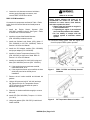
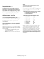
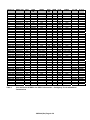
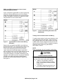
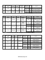
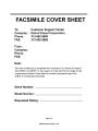
18SP546* – Install DDEC II to DDEC IV Wire Harness and
Hardware Conversion Kit on 1991-1993 Series 60®
On-Highway Manual Transmission Trucks
*Revision – 12/14/04
6SE483 and the DDEC III/IV SECM Troubleshooting
Guide, 6SE497 for instructions on removing, installing,
and testing the other parts required for kit installation.
Introduction
Service kit R23529490 permits conversion of a Detroit
Diesel Series 60® DDEC® II engine to a DDEC IV
configuration. The kit includes the items listed in
Table 1.
Kit Part Number
R23519307
23512307
23513558
23517986
23518358
Qty.
1
8
1
1
1
23520380
1
23520381
1
23518206
1
23518359
1
23515251
1
23519124
1
23509744
11506101
23515250
3
3
1
23517875
18SP546
3
1
Table 1
Description
ECM
Isolator
Engine Harness
Power Harness Adaptor
Injector Harness, Jake
Brake®
Coolant Level Sensor
(CLS)- 1/4” -18 NPTF
Coolant Level Sensor
(CLS) - 3/8”-18 NPTF
Adaptor Module, Coolant
Level Sensor
Harness Asm., Coolant
Level Sensor Jumper
Liner
Coolant Temperature
Sensor (CTS) - ¾ in.
brass
Heat Shield, Exh.
Manifold
Stud Bolt, M10, 1.5x120
Nut, M10
Air Temperature Sensor
(ATS)
Intake Manifold Gasket
Installation Instructions
DDEC II to DDEC IV Conversion Kit,
P/N: 23529490
DDEC II ECM Removal
Remove the ECM as follows:
PERSONAL INJURY
To avoid injury from hot surfaces, wear
protective gloves, or allow engine to cool
before removing any component.
PERSONAL INJURY
To avoid injury from accidental startup
while servicing the engine, disconnect the
starting system.
1. With the engine at ambient temperature (cool to
the touch) and the starting system disconnected/
disabled, disconnect the power harness from
vehicle batteries.
2. Loosen the wire harness connector hold-down
screws, and gently disengage the connectors
from ECM sockets.
3. Remove the DDEC II injector and engine
sensor harness from the engine.
Following are instructions for installing the parts in the
kit. Refer to the current Series 60 Service Manual,
18SP546 (Rev) Page 1 of 8
4. Loosen the wire harness connector hold-down
screws, gently disengage connectors, and
remove DDEC II ECM from vehicle.
DDEC IV ECM Installation
Conversion kit components are listed in Table 1. Refer
to the Series 60 Service Manual and install parts as
follows:
1. Install the Engine Sensor Harness (P/N:
23513558), included in the kit. See Figure 1. Refer
to Section 8.6 of Service Manual.
2. Install the Injector/Jake Brake® harness
(P/N: 23518358) included in the kit.
3. Install new Coolant Level Sensor (CLS) (either ¼”
P/N: 23520380 or 3/8” P/N; 23520381). Refer to
Section 2.34 of Service Manual.
PERSONAL INJURY
Diesel engine exhaust and some of its
constituents are known to the State of
California to cause cancer, birth defects,
and other reproductive harm.
• Always start and operate an engine in
a well ventilated area.
• If operating an engine in an enclosed
area, vent the exhaust to the outside.
• Do not modify or tamper with the
exhaust system or emission control
system.
12. Reconnect starting power. Start the engine and
check for proper DDEC system operation.
4. Install the CLS adaptor module (P/N: 23518206)
and jumper adaptor (P/N: 23518359).
5. Install the Coolant Temperature Sensor (CTS)
(P/N: 23515251) at right rear of head. Refer to
Section 2.31 of Service Manual.
6. Install the heat shield (P/N: 23519124) using stud
bolts (P/N: 23509744) and nuts (P/N: 11506101).
a) If the engine has current exhaust manifold,
install heat shield “as is.”
b) If the engine has former style manifold, the heat
shield may need to be altered prior to
installation.
Figure 1
DDEC IV ECM and Wiring Harness
Locations
Figure 2
Air Temperature Sensor Location
7. Remove the air intake manifold and discard old
gaskets.
8. Using a drill press and a 9/16” drill, drill and tap a
3/8” pipe port for the Air Temperature Sensor
(ATS), between #3 and #4 intake air ports in
manifold. See Figure 2.
9. Clean the air intake manifold thoroughly to remove
drill chaff.
10. Install ATS (P/N: 23515250). Torque to 11-16 N·m
(8-12 lb·ft).
11. Using new gaskets (P/N: 23517875), install the air
intake manifold.
18SP546 (Rev) Page 2 of 8
NOTE:
Vehicle speed sensors must be used for these two
features to operate properly.
Powernet Engine Order Entry,
Change Unit Information
In order for the newly installed DDEC IV ECM to be
programmed, a mainframe file must be established. To
ensure that the ability to program the DDEC IV ECM is
established, the attached FAX form (See Figure 5) must
be filled out and sent to the DDC Customer Support
Center at (313) 592-5888. See Table 2 for the
appropriate 6N4D and 6N4M groups.
For example, there is only one DDEC IV rating released
for the 11 liter engines: 6N4D7275 is a 400/357 @
1800/2100-1350 lb·ft.
Important Information – Please read.
To reduce the maximum rated speed from 2100 to
1800 rpm, set progressive shift as follows:
• LG1 rpm limit 1800
• LG1 max rpm 1800
• LG1 max mph 12
• LG2 rpm limit 1800
• LG2 max rpm 1800
• LG2 max mph 44
• HG max rph 1800
• HG min mph 45
You must use the updated fax request in these
instructions, or request the mainframe update to “DDEC
IV,” otherwise the wrong calibration could be assigned.
The DDEC IV ECM in this kit is only for use with
12-volt systems.
Within the ratings listed, you will find the original DDEC
II-III ratings and a cross-reference to the comparable
DDEC IV version.
With the following features now found within the DDEC
system, it is possible to cover a wide variety of requests
with fewer ratings:
• Low gear torque limiting will modify the max.
torque for the application.
• Progressive shift will limit the max RPM for the
user.
To reduce the maximum torque from 1350 to 1250 lb·ft:
• Set the low gear torque limit to 1250
• Set the threshold to 0.1
DDEC II to DDEC IV UPC groups are listed in Table 2.
To ensure that the engine is serviced properly after
being converted from DDEC II to DDEC IV, and to
ensure that other modifications may be made, DDC’s
unit history file must be updated. If this is not done,
subsequent engine service and/or repair work might be
done using incorrect parts. Complete the attached FAX
form and send it to the DDC Customer Support Center.
See Figure 5.
18SP546 (Rev) Page 3 of 8
DDEC IV
DDEC II/III
CWC
Rated
HP
@RPM
6N4D-7275
N/A
N/A
N/A
6N4D-6309
6N4M-6149
6N4M-6153
6N4M-6167
235
239
354
350
320
320/350
6N4D-7275
N/A
N/A
N/A
N/A
6N4D-6310
6N4M-6214
6N4M-6215
6N4M-6203
6N4M-6216
414
413
371
415
6N4D-7275
N/A
N/A
N/A
6N4D-6311
6N4M-6154
6N4M-6157
6N4M-6371
6N4D-7275
N/A
FT·LB
@RPM
1800
1800
1800
1250
1250
1250
1200
1200
1200
365
350
325
325/350
1800
1800
1800
1800
1350
1350
1350
1350
1200
1200
1200
1200
240
243
478
320
285
285/320
1800
1800
1800
1150
1150
1150
1200
1200
1200
6N4D-6312
6N4M-6148
234
320
2100
350
1800
1250
1200
6N4D-7275
6N4M-7815
6N4D-7127
6N4M-6916
1261
357
2100
400
1800
1350
1200
6N4D-7274
6N4M-7811
6N4M-7812
6N4M-7813
6N4M-7814
6N4D-6313
6N4M-6374
6N4M-6211
6N4M-6200
6N4M-6372
433
416
253
479
450
430
425
425/450
2100-1800
2100-1800
2100-1800
2100-1800
1450
1450
1450
1450
1500-1200
1500-1200
1200
1200
6N4D-7272
6N4M-7804
6N4M-7805
6N4M-7806
N/A
6N4D-6314
6N4M-6212
6N4M-6164
6N4M-6166
6N4M-6213
417
250
252
359
430
400
365
365/400
1800
1800
1800
1800
1450
1450
1450
1450
1500-1200
1200
1200
1200
6N4D-7272
6N4M-7804
6N4M-7805
6N4M-7806
6N4M-7807
6N4D-6315
6N4M-6212
6N4M-6164
6N4M-6166
6N4M-6213
417
250
252
418
430
400
365
365/430
1800
1800
1800
1800
1450
1450
1450
1450
1500-1200
1200
1200
1200
6N4D-7273
6N4M-7808
6N4M-7809
6N4M-7810
6N4D-6316
6N4M-6161
6N4M-6165
6N4M-6202
247
251
373
400
365
365/400
2100
2100
2100
1450
1450
1450
1200
1200
1200
Table 2
Other
HP
425
@RPM
1800
Inj. P/N
Inj. P/N
5234935
5235605
5234935
5235605
5234935
5235605
5234935
5235605
5234935
5235605
5234935
5235605
5234970
5235695
5234940
5235600
5234940
5235600
1991-1993 Series 60 DDEC II to DDEC IV Conversion – On-Highway Trucks with Manual
Transmissions
18SP546 (Rev) Page 4 of 8
DDEC II to DDEC IV Conversion Cruise Control
Switch Wiring Modifications
Figure 3 illustrates a typical DDEC II cruise control wiring
schematic. Wiring modifications to the Cruise Enable
Switch and the Set/Coast Switch are required whenever
a DDEC II to DDEC IV conversion is made on a vehicle
using the DDEC II cruise control feature.
Figure 4
Cruise Control Wiring Schematic after
Modification
Testing of Cruise Control Switch and Wiring
Figure 3
Typical DDEC II Cruise Control Wiring
Schematic
Remove the wire identified as DDEC circuit #542 from
the Set/Coast Switch. At a convenient point, splice circuit
#542 into the cruise control switched ground circuit.
Cruise control switched ground is the circuit that is
“open” when the Cruise Enable Switch is turned OFF
and “grounded” when the Cruise Enable Switch is turned
ON. If necessary, use a volt-ohm meter to verify the
circuit before splicing in circuit #542. Depending on the
application, the switched ground circuit may be identified
as DDEC circuit #558 or a branch of DDEC battery
ground, such as circuit #953A, #953B, or #953C, etc.
See Figure 4.
To speed up the testing of cruise control switches, quick
check tables have been developed. These tests are to
be run with the ignition ON, and the engine not running.
A DDR / DDDL must be plugged into the connector. All
three quick check tables must be completed to properly
check the cruise control wiring and switches.
See Tables 3, 4 and 5.
NOTE:
When all tests pass, the unit is ready for road testing.
LOSS OF VEHICLE CONTROL
To avoid injury from the loss of vehicle control, do
Not use cruise control under these conditions:
• When it is not possible to keep the
vehicle at a constant speed (on winding
roads, in heavy traffic, in traffic that varies
in speed, etc.)
• On slippery roads (wet pavement, ice-or
snow-covered roads, loose gravel, etc.)
18SP546 (Rev) Page 5 of 8
Step
1
2
Table 3
Step
1
2
3
4
Table 4
Cruise Enable
Switch
Set/
Coast
Switch
Res/
Accel
Switch
DDR/DDDL
Display
Okay
?
Off
Yes
Go To
—
Refer to Sec. 10.7 of DDEC
On
No
III/IV SECM TS Manual
Refer to Sec. 10.7 of DDEC
Off
No
Cruise
On
Off
Off
III/IV SECM TS Manual
Enable
On
Yes
—
Cruise Control Quick Check Table, Testing Cruise Enable Switch and Wiring
Off
Cruise Enable
Switch
Off
Cruise
Enable
Off
Brake
Pedal
Clutch
Pedal
DDR/DDDL
Readout
DDR/DDDL
Display
On
Okay
?
Yes
Go To
—
Refer
to
Sec.
10.7 of
On
Released
Released
Off
No
DDEC III/IV SECM
TS Manual
Refer to Sec. 10.7 of
Service
On
No
DDEC III/IV SECM
On
Depressed
Released
Brake
TS Manual
Release
Off
Yes
—
On
Yes
—
Clutch
Refer
to
Sec.
10.7 of
On
Released
Released
Release
Off
No
DDEC III/IV SECM
TS Manual
Refer to Sec. 10.7 of
Clutch
On
No
DDEC III/IV SECM
On
Released
Depressed
Release
TS Manual
Off
Yes
—
Cruise Control Quick Check Table, Testing Brake and Clutch Switch and Wiring
Service
Brake
Release
Step
Cruise Enable
Switch
Set/
Coast
Switch
Res/
Accel
Switch
1
On
Off
Off
2
On
On
Off
3
On
Off
Off
4
On
Off
On
Table 5
DDR/DDDL
Readout
DDR/DDDL
Readout
Set/Coast
Set/Coast
Res/Accel
Res/Accel
DDR/DDDL
Display
Okay
?
Off
Yes
On
No
Off
No
On
Off
Yes
Yes
On
No
Off
No
On
Yes
Go To
—
Refer to Sec. 10.7 of DDEC III/IV
SECM TS Manual
Refer to Sec. 10.7 of DDEC III/IV
SECM TS Manual
—
—
Refer to Sec. 10.7 of DDEC III/IV
SECM TS Manual
Refer to Sec. 10.7 of DDEC III/IV
SECM TS Manual
—
Cruise Control Quick Check Table, Testing Set/Coast and Resume/Accel Switches and Wiring
18SP546 (Rev) Page 6 of 8
Figure 5
18SP546 (Rev) Page 7 of 8
®
®
®
Copyright© 2004 Detroit Diesel Corporation. Detroit Diesel , DDC , Series 60 , and the spinning arrows design are registered trademarks of
Detroit Diesel Corporation. All other trademarks are the property of their respective owners.
18SP546 (Rev.) 0412 As technical advances continue, specifications will change. All rights reserved. Printed in U.S.A.
18SP546 (Rev) Page 8 of 8