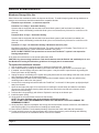
1
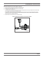
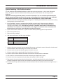
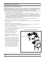
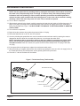
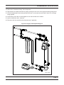
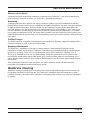
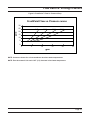
FreshPoint™ U440
Service Manual
IMPORTANT: Fill in Pertinent Information on Page 3 for Future Reference
Table of Contents
Installation & Start-Up Checklist............................................................................................................................. 3
Product Specifications & Important Information..................................................................................................... 4
Safety, Cautions, & Warnings................................................................................................................................. 5
Flushing Schedule & Installation Instructions......................................................................................................... 6
Installation Instructions........................................................................................................................................... 7
Basic Programming Quick Reference Guide........................................................................................................ 22
Programming........................................................................................................................................................ 23
Service & Maintenance........................................................................................................................................ 29
Troubleshooting.................................................................................................................................................... 31
Flow Rate vs. Driving Pressure............................................................................................................................ 33
IMPORTANT PLEASE READ:
•
The information, specifications and illustrations in this manual are based on the latest information available at the time of printing.
The manufacturer reserves the right to make changes at any time without notice.
•
This product should be installed by a plumbing professional.
•
This unit is designed to be installed on potable water systems only.
•
This product must be installed in compliance with all state and municipal plumbing and electrical codes. Permits may be required
at the time of installation.
•
If daytime operating pressure exceeds 80 psi, nighttime pressures may exceed pressure limits. A pressure reducing valve must be
installed.
•
Do not install the unit where temperatures may drop below 32°F (0°C) or above 104°F (40°C).
•
Do not place the unit in direct sunlight.
•
Do not strike any of the components.
•
Warranty of this product extends to manufacturing defects of the vessel and controller, not the membrane. Misapplication of this
product may result in failure to properly condition water, or damage to product.
•
A prefilter should be used on installations in which free solids are present.
•
In some applications local municipalities treat water with Chloramines. High Chloramine levels may damage system components.
•
Correct and constant voltage must be supplied to the controller to maintain proper function.
Installation & Start-Up Checklist
•
•
•
•
Use this form to record initial system hardware, site conditions, and controller programming information.
Retain a copy for future reference.
Fill in the appropriate data (if available).
Checklist data should be collected and logged on this form for each system installed.
Start-up Data:
Installation Date: ___________________________
Installer: _________________________________
Installation Site: ___________________________
Application: _______________________________
System Model/Serial Number: ______________
Water Source: ___________________________
Water Analysis:
Turbidity: _____________________________
Total Iron: _____________________________
Water Temperature: _____________________
System Inlet Pressure (if available): ________
System Outlet Pressure: (if available):_______
Flow Rate During Pressure Reads: _________
Chlorine: _____________________________
Pretreatment Installed: ______________________
Back-flush Kit Installed: Yes ________ No _______
Set Volume Between Flushes: ____________
Checklist of Installation/Start-Up Steps
1.
Installation location allows access to membrane ___
2.
Mounting provision accommodates system weight ___
3.
Listed components/fittings present ___
4.
Loose components assembled to system ___
5.
System securely mounted ___
6.
Solenoid valve/flow meter signal connections ___
7.
Plumbing connections completed ___
8.
Initial flush w/o leaks ___
9.
Electrical power connected ___
10. System sanitized ___
11. Back-up battery installed in controller ___
12. Controller display okay ___
13. Time of day set ___
14. All programming steps completed ___
15. Proper operation verified ___
16. Installation/Set-Up information entered onto form ___
Set Flushing Duration: __________________
Set Day Override: __________________________
Initial Product Water Flow Rate: _______________
_________________________________________
Other Program Details: ______________________
_________________________________________
General Notes:
_________________________________________
_________________________________________
_________________________________________
Specific Installation Notes
(Problems/Suggestions/Comments):
_________________________________________
_________________________________________
_________________________________________
_________________________________________
_________________________________________
_________________________________________
_________________________________________
_________________________________________
_________________________________________
Page Product Specifications & Important Information
Introduction to the FreshPoint™ Ultrafiltration System
The FreshPoint™ ultrafiltration system is an advanced Point of Entry (POE) water treatment device designed to
improve the water quality in the entire home. It uses ultrafiltration membrane technology to provide a physical barrier
to particles, large dissolved molecules, most colloids, and microbes down to 0.025 um in size. The FreshPoint™ is not
designed to removed ions or other elemental forms such as hardness and heavy metals, or small organic molecules
such as pesticides.
The FreshPoint™ should only be installed by a qualified professional. The installation must comply with all local codes
and state or provincial laws and regulations.
In addition to meeting codes, laws, and regulations, the home owner should understand the care and maintenance of
the FreshPoint™. Please read the information found in this service manual.
SAFETY NOTICE: Read all safety precautions before installing, operating, or servicing the FreshPoint™.
Product Specifications
Technical Data and Specifications
pH Range During Operation.............................. 3-10
Free Chlorine
............................................... Max. 200 mg/L for cleaning, 4 mg/L for service
Maximum Continuous Flow............................... Recommended 1.2 gpm (surface waters) to 2.9 gpm (well water)
Maximum Intermittent Flow............................... 10 gpm
Recommended Operating Pressure.................. up to 60 psig
Maximum Operating Pressure.......................... 120 psig
Minimum Operating Temperature...................... 33°F (Do Not Freeze)
Maximum Operating Temperature..................... 104°F
Contaminant Removal Size............................... 150,000 daltons molecular weight cut-off
0.025 um nominal pore size
Multibore® Capillaries
Capillaries per Fiber.............................................................................7
Outer Diameter.......................................................... Inch....................0.17
Inner Diameter.......................................................... Inch....................0.04
Material................................................................................................PESM
Molecular Weight Cutoff (MWCO)............................. k Daltons............100-150
Active Membrane Surface......................................... ft2. ......................48.50
IMPORTANT! READ THIS FIRST
Read this service manual thoroughly before first use.
•
•
•
•
•
•
•
•
•
All plumbing and electrical codes must be complied with when installing this product.
Only qualified personnel should install this product.
Check the FreshPoint™ periodically to ensure proper operation (i.e.: flushing, flow rate, pressure drop, etc)
Do not allow the FreshPoint™ to be exposed to freezing temperatures. Freezing may damage the system.
Ensure the membrane does not dry out. Opened membranes should be preserved with a 0.1% sodium bisulfite
solution.
The FreshPoint™ will continue to operate as a filter during power loss. However, when power returns after an
extended outage, the timer may need reprogramming.
Keep this service manual near the FreshPoint™ system for future reference.
The FreshPoint™ is intended to treat only potable quality water. It is not intended as the permanent primary
treatment of water from a source that is contaminated, such as from radon, pesticides, insecticides, sewage, or
wastewater.
Use lubricants (such as silicone) sparingly.
Page Safety, Cautions, & Warnings
Safety
•
The FreshPoint™ must be wired according to local electrical codes to prevent the possibility of
electrical shock.
•
Do not modify the power supply cord.
•
The FreshPoint™ must be installed in compliance with local plumbing codes and any other applicable codes.
•
The FreshPoint™ has been designed and tested to offer reliable service when installed by a qualified
professional and operated and maintained according to the instructions in this service manual.
•
For safety reasons, the FreshPoint™ is furnished with a low voltage power transformer to plug into the
electrical outlet. Do not replace this transformer with another power supply (except as supplied by the
manufacturer), as this may cause damage to the electronics.
•
Install the FreshPoint™ only for its intended use as described in this service manual.
•
Do not use corrosive chemicals in the FreshPoint™.
•
Do not install the FreshPoint™ if it has a damaged cord or plug, if it is not working properly, or if it has been
damaged or dropped.
•
Do not immerse the cord or plug in water.
•
Keep the cord away from heated surfaces.
•
Disconnect the FreshPoint™ from the power source before performing any service or maintenance on the
controller, meter, or solenoid valves.
•
Do not plug in the controller transformer if there is water on the electrical wiring or the power supply.
•
Always shut off the water flow and release water pressure before cleaning or maintaining the FreshPoint™.
•
The FreshPoint™ is intended for indoor use only. The power supply and controller must not be exposed to
weather elements.
•
The outlet used for power to the FreshPoint™ should be an unswitched outlet.
NOTE: This product should be installed by a qualified professional. Comply with all plumbing and
electrical codes when installing this product.
Page Flushing Schedule & Installation Instructions
Flushing Schedule
The FreshPoint™ is flushed on a schedule dependent on the quality of water being treated.
Default Factory Settings
Flush Frequency:
100 gallons
Flush Duration:
0.5 minutes
Day Override:
1 Day
These settings may need to be adjusted based on the analysis for the water treated and practical experience
with fouling. The FreshPoint™ will automatically initiate a flush if 24 hours (for each 1 day of the Day Override
setting) has elapsed since the last flow initiated flush. This setting is adjusted in the day override setting in master
programming.
A post-ultrafilter pressure tank is recommended to ensure sufficient flow and pressure to the home during a flush
cycle. The backflush surge tank (where installed) will perform the same function.
Refer to Table 1 below for initial set up.
Table 1: Initial Recommended Flushing Parameters by Water Source and Treatment
Water Source
Typical Water Quality to Filter
(with recommended pretreatment)
Recommended
Pretreatment1
Backflush Kit
Flush Frequency
(Gallons
Throughput)
Flush
Duration
(Seconds)
Surface Water
(Municipally Treated)
• Chlorine < 4.0 mg/l
• Turbidity < 1.0 NTU
• TOC < 2.0 mg/L
• SDI15 < 6.67
• Metals (Fe, Mn, Cu, etc.) < 1 mg/l
• 200 micron prefilter
Recommended
100
30
Surface Water (Private
Multi Barrier Treatment)
• Chlorine > 2mg/l, < 4.0 mg/l
• Turbidity < 5.0 NTU
• TOC < 10.0 mg/L
• SDI5 < 20
• Metals (Fe, Mn, Cu, etc.) < 1 mg/l
• In-Line coagulation and
filtration with multimedia
filter
• Disinfection with chlorine
• 200 micron prefilter
Recommended
50
60
Well (Municipally
Treated)2
• Chlorine < 4.0 mg/l
• Turbidity < 1.0 NTU
• TOC < 2.0 mg/L
• SDI15 < 6.67
• Metals (Fe, Mn, Cu, etc.) < 1 mg/l
• Iron removal filtration
(if iron over 1 mg/l)
• 200 micron prefilter
Recommended with
high turbidity,
suspended solids,
colloids, or ferric iron
200
30
Well (Private)2
• Chlorine < 4.0 mg/l
• Turbidity < 1.0 NTU
• TOC < 2.0 mg/L
• SDI15 < 6.67
• Metals (Fe, Mn, Cu, etc.) < 1 mg/l
• Iron removal filtration
(if iron over 1 mg/l)
• Disinfection – optional
• 200 micron prefilter
Recommended with
high turbidity,
suspended solids,
colloids, or ferric iron
100
30
In all cases, a disposable pre-filter cartridge is recommended to protect the FreshPoint™ from large particles,
plumbing debris, etc.
2
Some shallow wells may have serious contamination problems, hazy water, high TOC, color and high bacterial
loads. The backflush kit is recommended to avoid fouling in these installations.
NOTE: It is important to understand the water quality and fouling potential to determine the type of
flushing required when installing the FreshPoint™.
1
Flow Capacity
• Assess the household water use, especially peak water draw. The standard single-element FreshPoint™ is
sized for 10 gpm peak capacity flow. Water draw in the house that exceeds peak capacity will have the effect
of reduced pressure and volume delivery at the open taps.
• Maximum recommended continuous flow for the FreshPoint™ system is 1.2 gpm for surface water, and 2.9
gpm for well water.
Page Installation Instructions
Plumbing
•
The system and installation piping should be cleaned before the system is started so that no impurities,
abrasive materials, or oily materials are washed into the membranes. The piping must be purged of air to
prevent water hammer which can damage the system.
•
A bypass system is strongly to permit the most efficient service of the FreshPoint™ over its life. Additionally,
some local plumbing codes may require a bypass.
•
All three FreshPoint™ housing ports on the system (inlet, filtrate or outlet, and drain) are 3/4” NPT
connections.
•
A 10 gpm flow control is included to be installed on the inlet of the FreshPoint™ to ensure the membrane
operates in an efficient manner.
•
A 7 gpm flow control is included to be installed on the drain line to maximize water efficiency and ensure
proper flushing rates are achieved. Ensure the drain selected has the capacity for this flow rate.
•
Private wells often have higher levels of turbidity or suspended solids that can shorten membrane life without
adequate flushing. If fouling potential is high, a backflush kit should be installed. The installation of a pressure
tank and solenoid valve switches the system from forward flushing to backflushing, thereby extending the
membrane life in high fouling potential waters.
For standard installations, a post-ultrafilter pressure tank is recommended to maintain pressure during a flush
cycle.
The system must be protected from possible back contamination by the installation of an air gap between the
FreshPoint™ drain connection and the drain line.
•
•
Electrical Requirements
The FreshPoint™ controller requires a constant electrical supply to flush correctly (120 VAC).
Pretreatment
Pretreatment of the FreshPoint™ with a 200 µm filter is recommended. Some installations may require additional
pretreatment. Reference the Flushing Schedule (Table 1) or the FreshPoint™ Ultrafiltration Systems Applications
Guide for more information.
FreshPoint™ Location
•
•
•
•
•
•
•
•
Note the location of the water supply, drain and an electrical outlet when choosing a mounting location.
The FreshPoint™ is a point-of-entry (POE) device designed to treat water distributed throughout the entire
plumbing system. The installation should be located near the point of entry, but ahead of where plumbing
splits for distribution.
The system mounting bracket has been designed to mount the FreshPoint™ sufficiently off the wall to
accommodate installation of a pre/post filter inline with the water inlet and/or water outlet of the system.
Remember to allow for visual and physical access to the meter/programming controls.
Do not mount the FreshPoint™ above any electrical equipment, or above items that may become damaged if
they get wet.
Install the FreshPoint™ in a location that will allow for easy service access. Service and maintenance requires
access to the unit and removal and replacement of the membrane element.
Mount the FreshPoint™ to a wall in a vertical orientation using appropriate mounting hardware (not included)
capable of supporting 51 pounds (23.1 kilograms).
The FreshPoint™’s footprint is 12” x 12”, exclusive of plumbing connections. The FreshPoint™ requires 85”
of vertical room to allow for removal of the membrane, unless plumbing accommodations are made (e.g.:
unions). See Figure 3 for a typical installation with dimensions.
The backflush tank, in the backflush kit, requires an additional 16” by 16” of level floor space.
Plumbing Options
There are two options for plumbing in the FreshPoint™ system:
1. Standard Installation (Forward Flush only)
2. Backflush Kit Installation
Page Installation Instructions
Standard Installation (Forward Flush only)
A standard installation clears the membrane periodically by opening a drain port, and allowing the feed stream
flow in its normal direction, but at a faster rate. The flow goes in and out of the end of the fiber instead of through
the membrane, and the foulant is cleaned off the membrane and out of the unit to drain.
Connect the FreshPoint™ to the household plumbing supply as shown in Figure 1. It is recommended that the
plumbing include a system bypass for future service. A 200 um sediment pre-filter is recommended. For ease of
membrane element replacement, unions are recommended as indicated on Figure 1.
NOTE: Installations without a pressure tank may experience drops in pressure/flow to the home during a
flush cycle.
Figure 1: Tankless Installation
Drain Flow Control
(Note Flow Direction)
Flow Meter Housing
(Note Flow Direction)
Outlet Valve
Outlet
Inlet
Bypass Valve
Inlet Valve
Pre-filter (Recommended)
Drain
Piping Must
Include
Code-Compliant
Air Gap
Inlet Flow Control
(Note Flow Direction)
1/4” Ball Valve Pressure Tap
for Membrane Integrity Testing
(Recommended)
42605_REVA
Page Installation Instructions
Backflush Kit Installation
Installations with high fouling potential will require plumbing in a pressurized surge tank and inlet solenoid
valve (See Flushing Schedule Table 1). In the backflush mode, the filtered water from a pressure tank flows
backward through the membrane from the filtrate side during the flushing cycle. This removes the foulant from the
membrane surface as well as material that may have entered into the porous structure.
Connect the FreshPoint™ to the plumbing supply as shown in Figure 2. It is recommended that the plumbing
include a system bypass for future servicing, etc. A 200 um sediment pre-filter is recommended. For ease of
membrane element replacement, unions are recommended as indicated on Figure 2. The backflush tank should
be installed on a tee before the flow meter. The backflush tank precharge pressure should be set to 20 psig.
NOTE: Installation of the backflush tank after the meter will cause reverse flow through the meter and
could have a detrimental effect on meter performance.
Figure 2: Backflush Kit Installation
Drain Flow Control
(Note Flow Direction)
Flow Meter Housing
(Note Flow Direction)
Outlet Valve
Outlet
Inlet
Bypass Valve
Tank Isolation Valve
Inlet Valve
Drain
Pre-filter (Recommended)
Piping Must
Include
Code-Compliant
Air Gap
Backflush Inlet Shut-Off Valve
1/4” Ball Valve Pressure Tap
for Membrane Integrity Testing
(Recommended)
42606_REVA
Page Installation Instructions
Figure 3: Dimensional Drawing for the FreshPoint™ Ultrafiltration System
[2159]
85.00
Vertical Clearance
Required to
Remove Membrane
[90.66]
3.57
[266.41]
10.57
[357.51]
14.08
[299.82]
11.80
[184.09]
7.25
[1250.89]
49.25
[1350.61]
53.17
[187.96]
7.40
[6.35]
Ø.25
[250.70]
9.87
61593_REVJ
NOTE: Dimensions are in inches. Metric (mm) dimensions are in brackets.
Page 10
FreshPoint™ Assembly
Figure 4: FreshPoint™ Assembly and Included Parts
Open End of
Membrane Assembly
Faces Up
9
1
10
6
2
3
13
11 12 11
1
5
4
5
7
8
5
61593_REVJ
Item No.
Quantity
Part No.
Description
1................... 1......................61594-02................... Codeline Vessel Assy, UF-Filter
2................... 1......................61595-03................... UF Filter Element Assy, 4”
3................... 1......................42335........................ Spring, Codeline, U440 Filter
4................... 2......................41972........................ Bracket, Mounting, UF Filter
5................... 2......................41976........................ Saddle & Clamp Assy
6................... 1......................61592-01................... Timer Assy, UF, ET, 120VAC
..................... 1......................61592-03................... Timer Assy, UF, ET, 230VAC, EU
..................... 1......................61592-04................... Timer Assy, UF, ET, 230VAC, AU
7................... 1......................61650........................ Fitting Kit, Inlet
8................... 1......................60700-10................... DLFC, 3/4”F x 3/4”F, NPT, 10 GPM, Brass
9................... 1......................61663........................ Fitting Kit, Outlet
10................. 1......................61560-11.................... Meter Assy, 3/4”, Inln, NPT, Elec
11................. 1......................61652........................ Fitting Kit, Drain
12................. 1......................42556........................ Bracket, Solenoid, 1/2”, NPT, NC
13................. 1......................60699-70................... DLFC, 3/4”F x 3/4”F, NPT, 7.0 GPM, Brass
Page 11
Installation Instructions
Additional Water Treatment Devices
•
•
•
It is preferable to install the FreshPoint™ ahead of softeners and carbon filters, as the removal of particulates
generally improves their performance. The FreshPoint™ should be installed after equipment such as iron filters,
sediment filters, or multimedia filters.
Installation downstream of a chlorinator runs the risk of oxidative attack of the membrane, shortening the membrane
life depending on chlorine level, time of contact and temperature. The FreshPoint™ can withstand a continuous
dose of up to 4.0 mg/L (or ppm) of free chlorine, but continuous exposure to higher level of free chlorine or other
oxidizing chemicals can shorten the life of the membrane.
When installed on a chlorinated water supply of less than 4.0 mg/L free chlorine, it is preferable to allow the chlorine
to pass through the FreshPoint™.
FreshPoint™ Installation Instructions
Tools and Supplies needed:
1. Teflon® thread tape or paste for leak free assembly of the pipe thread connections.
CAUTION: Ensure that the paste is compatible with plastic fittings.
2. Lubricant for seals (a packet of silicone is supplied)
NOTE: Silicone (supplied) should be applied sparingly to avoid fouling the membrane.
3. Four ¼” bolts to mount the system to the wall.
4. ½” open end wrench to tighten saddle clamp.
5. 7/16” open end wrench to tighten ¼” wall mount bolts.
6. Crescent wrench that can open to 1 ½” to grip flow control.
7. Pipe wrench to grip the vessel’s side port.
8. Flat head screw driver and pliers to remove the vessel’s vessel retaining ring.
Unpacking (Refer to Figure 4, FreshPoint™ Assembly)
1. Open the box with the hardware and verify that all of the components pictured on the FreshPoint™ Assembly page
are present and undamaged.
2. Open the Plumbing Kit bags, and verify that all of the components listed on the parts list (found in the Plumbing Kit
bags) are present and undamaged.
3. The membrane is packed in a preservative solution, and should not be opened until it is to be installed in the
housing.
Hardware Assembly (Standard Assembly):
1. Assembly is most easily done on a horizontal surface.
2. Position a mounting bracket (Item 4), a saddle, and a saddle clamp (Items 5) about 10” from the top of the vessel
(Item 1). Leave the bolts loose. Note: The smaller diameter portion of the mounting bolt holes in the mounting
bracket must be positioned toward the top of the vessel.
3. Position the bracket of the timer (Item 6) between the mounting bracket and the saddle clamp. Ensure timer is
oriented correctly.
4. Rotate the vessel so that the side ports are oriented in the direction compatible with the site plumbing and tighten
the saddle clamp bolts with the ½” wrench.
5. Install the remaining mounting bracket, saddle, and saddle clamp at a convenient location near the bottom of the
vessel, and tighten the saddle clamp bolts with a ½” wrench.
Vessel Head Removal
1. Remove the top end closure, bottom end closure, and two square cross section seals from the vessel.
a. Remove the retaining rings by prying the tabbed end out of the stainless steel groove with the tip of the
screwdriver. Once the end of the retaining ring is clear of the groove, grasp the tab with the pliers and pull it toward
the end of the vessel until the end of the ring is resting in the end margin of the shell.
b. Remove the 4” retaining ring from the stainless steel groove in the shell by rotating your finger behind the ring as
it continues to exit the groove.
c. Once the retaining ring has been removed, examine the area for burrs or dings which could damage the head or
membrane. If necessary, use Scotch-Brite® or 600 grade sandpaper to smooth the area.
d. Grasp the adapter and pull the head straight out. A small amount of side-to-side movement may be necessary to
start the head moving.
Page 12
Installation Instructions
Outlet Fittings
1. Apply thread sealant to the ¾” NPT thread of the adapter (Item 1) of the top end closure and securely thread the
male half of the union (Item 9, Outlet Fitting Kit) to it.
2. Apply thread sealant to both ends of the ¾” NPT nipple (Item 9, Outlet Fitting Kit), and securely thread it to the
female portion of the union (Item 9, Outlet Fitting Kit) and the elbow (Item 9, Outlet Fitting Kit). If installing with the
backflush kit, substitute the backflush kit for the elbow (see Figure 2).
3. Remove the red retainer clips and the adapters from the ends of the meter assembly (Item 10).
4. Apply thread sealant to the 3/4” NPT thread of the meter assembly adapters.
5. Securely thread one of the meter assembly adapters into the elbow (Item 9, Outlet Fitting Kit). If installing with the
backflush kit, substitute the tee from the backflush kit for the elbow (see Figure 2).
Drain Fittings
1. Apply thread sealant to the NPT nipples and reducer bushings (Items 11, Drain Fitting Kit).
2. Securely thread the male half of the union (Item 11, Drain Fitting Kit) to the ¾” NPT nipple.
3. Securely thread a reducer bushing (Item 11, Drain Fitting Kit) to the female half of the union (Item 11, Drain Fitting
Kit) and a reducer bushing to the inlet end of the DLFC (Item 13). The flow direction is indicated on the body of the
flow control.
4. Securely thread one of the 1/2” NPT nipples (Item 11, Drain Fitting Kit) into each reducer bushing (Item 11, Drain
Fitting Kit).
5. Securely thread the inlet port of the solenoid valve (Item 12) onto the 1/2” nipple which is connected to the union.
The valves flow direction is indicated on the valve.
6. Securely thread the outlet port of the solenoid valve (Item 12) onto the 1/2” nipple which is connected to the 7 gpm
DLFC. The flow direction is indicated on the body of the flow control.
7. Securely thread the 3/4” NPT nipple (Item 11, Drain Fitting Kit) into the top port of the vessel (Item 1).
NOTE: Use a wrench to hold the vessel’s side port when tightening a fitting, movement of the port could
damage the shell and/or the port.
Inlet Fittings
1. Apply thread sealant to the 3/4” NPT nipples (Items 7, Inlet Fitting Kit).
2. Securely thread one of the nipples into the outlet of the 10 GPM flow control (Item 8). The flow direction is indicated
on the body of the flow control.
3. Securely thread female half of the union (Items 7, Inlet Fitting Kit) into the nipple extending from the 10 GPM flow
control. If installing with the backflush kit, insert the backflush kit inlet solenoid valve between the union and the
flow control (see Figure 2). If installing the recommended fittings for integrity testing, install immediately prior to the
union (see Figures 1 and 2).
4. Securely thread the male half of the union (Items 7, Inlet Fitting Kit) onto the other 3/4” NPT nipple (Items 7, Inlet
Fitting Kit).
5. Securely thread the 3/4” NPT nipple (Items 7, Inlet Fitting Kit) into the bottom port of the vessel (Item 1).
NOTE: Use a wrench to hold the vessel’s side port when tightening a fitting, movement of the port could
damage the shell and/or the port.
Insert Vessel Top Head
1. Install the square cut seal into the groove below the stainless steel ring at the top end of the vessel. The seal should
be lubricated lightly on the ID surface only with the supplied silicone.
2. Installing the head into the vessel.
a. Install the top closure into the vessel. Using both thumbs, apply equal pressure on opposite sides of the head
to force it into the vessel so that it clears the retaining ring groove.
b. Carefully insert the retaining ring into the groove. This is done by inserting the lead end of the spiral ring
(end without bent tab) into the stainless steel retaining ring groove located in the shell, slowly pushing the
remaining turns into the shell.
c. Check that the spiral retaining ring is fully seated in the groove. If it is not, remove it and check for foreign
materials that would cause the spiral ring to not fully seat.
Page 13
Installation Instructions
Connect Fittings to the Vessel
1. Connect the inlet end of the flow meter (Item 10) to the meter adapter which is threaded into the outlet elbow (Item
9), and secure it with the red clip. The flow direction is indicated on the body of the meter.
2. Connect the drain valve union (Item 11) to the union at the sideport near the top of the vessel (Item 1).
3. Connect the inlet union (Item 7) to the union at the bottom of the vessel (Item1).
NOTE: Use a wrench to hold the vessel’s side port when tightening a fitting, movement of the port could
damage the shell and/or the port.
4. Position the hardware assembly and vessel bottom head against the wall and mark the four mounting bolt locations.
Installing the Membrane Element (Item 7):
1. Lay the assembled vessel and fittings on a horizontal surface.
2. Cut open the sealed bag of the filter element at the end where the center tube is open. Lightly lubricate the center
tube with the supplied silicone.
3. Insert the filter element into the bottom of the vessel, with the open end of the center tube first, and removing the
plastic bag as it goes in. A slight resistance will be felt at the last inch of insertion, as the seals on the adapter are
compressed into the center tube of the element.
4. Install the square cut seal into the groove below the stainless steel ring at the bottom end of the vessel. The seal
should be lubricated lightly on the ID surface only.
5. Insert the spacer spring (Item 3). About ¼” of compression is required to compress it beyond the square cut seal.
6. Install the bottom closure.
a. Using both thumbs, apply equal pressure on opposite sides of the head to force it into the vessel, clearing the
retaining ring groove.
b. Carefully insert the retaining ring into the groove. This is done by inserting the lead end of the spiral ring (the end
without the bent tab) into the stainless steel retaining ring groove located in the shell, slowly pushing the remaining
turns into the shell.
c. Check that the spiral retaining ring is fully seated in the groove. If it is not, remove it and check for foreign
materials that would cause the spiral ring to not fully seat.
Mounting the Assembly on the Wall:
1. Install four ¼” bolts at the positions previously marked. Leave enough clearance between the wall and the bolt
heads to permit the mounting brackets to be slid into place.
NOTE: Bolts larger than ¼” may not fit through the keyhole openings in the mounting brackets.
2. Tighten the four wall mounting bolts.
3. Install the other meter adapter into the meter assembly and fully insert the red clip.
Plumbing Connection:
1. Connect the supply water to the inlet flow control, and complete supply plumbing. Couple the inlet union.
2. Connect the drain line plumbing to the drain flow control and couple the drain union.
3. Connect the meter adapter to the outlet plumbing and couple the outlet union.
NOTE: If installing with the backflush kit, complete the plumbing between the outlet tee and the backflush
tank (see Figure 2). The backflush tank pre-charge should be adjusted to 20 psi. If installed, the backflush
tank isolation valve should be closed.
Page 14
Installation Instructions
Meter/Solenoid Electrical Connection (Refer to Figure 5)
1. Connect the drain solenoid wire harness to the solenoid valve.
2. Insert the flow meter cable into the socket on the flow meter
3. If installing with the backflush kit:
a. Remove the two transformer leads from the terminal strip (terminals 4 and 5) and replace them with the leads
from the higher-rated transformer provided in the kit.
b. Install inlet solenoid’s wiring harness (backflush kit) to the control board. The inlet solenoid leads should be
installed in the same terminal locations as the drain solenoid (1-green, 2-black, 3-white). DO NOT connect the
wiring harness to the solenoid at this time.
4. Plug the power cord transformer into a 120V GFI outlet.
Figure 5: Meter/Solenoid Electrical Connection Diagram
24 VAC Transformer
TB1
B
Black
White
White
Black
Green
6
5
4
3
2
Black
White
Wt/Blk
Yellow
1
Solenoid Harness
42209_REVB
Page 15
Installation Instructions
System Startup Guidelines
Electrical
Follow the instructions in the programming section of this service manual to setup the timer.
Check the FreshPoint™ For Leaks
•
Ensure that all new plumbing connections, the three ports from the housing, and the two end cap perimeters
have no leaks. Correct if needed.
•
Manually initiate a flush cycle by pressing the Extra Cycle button. Ensure the drain solenoid valve opens and
that a robust flow goes to the drain, and that the drain can handle the flow.
Flushing
Flush the membranes prior to placing the system in service to remove the membrane storage solution.
NOTE: If installed, the backflush tank isolation valve should be closed. If there is a tank and no isolation
valve, ensure that each flush cycle fills and empties the backflush tank.
NOTE: If installed with the backflush kit, the inlet solenoid valve should not be connected to the wiring
harness for flushing, as it will not permit easy removal of air from the system if operating.
Rinse the preservative solution from the membrane as follows:
1. Close the bypass valve of the bypass plumbing arrangement.
2. Open the outlet valve of the bypass plumbing arrangement.
3. Slowly open the inlet valve of the bypass plumbing arrangement. This will fill the module with water without
creating a water hammer effect.
4. To expel air from the feed side of the membrane initiate at least two successive flush cycles by pressing the
Extra Cycle button on the timer.
Rinse Cycle 1:
1. Open the service water faucet closest to the FreshPoint™ installation to permit a flow of five gallons per
minute. Allow the system to flush for twenty minutes.
2. Initiate two successive flushes to drain by pressing the Extra Cycle button on the timer.
3. If a backflush tank is installed and not isolated, ensure that it is emptied by initiating successive flushes by
pressing the Extra Cycle button on the timer.
Rinse Cycle 2:
1. Allow the service water to continue to flow at five gallons per minute. Permit the system to flush for an
additional twenty minutes.
2. Initiate two successive flushes to drain by pressing the Extra Cycle button on the timer.
3. If a backflush tank is installed and not isolated, ensure that it is emptied by initiating successive flushes by
pressing the Extra Cycle button on the timer.
Rinse Cycle 3:
1. Allow the service water to continue to flow at five gallons per minute. Permit the system to flush for an
additional twenty minutes.
2. Initiate two successive flushes to the drain by pressing the Extra Cycle button on the timer.
3. If a flush tank is installed, ensure that it is emptied by initiating successive flushes by pressing the Extra Cycle
button on the timer.
4. While the system is flushing check all plumbing connections for any possible leaks.
Page 16
Installation Instructions
System Sanitizing - With Prefilter Installed
The unit should be sanitized/disinfected after the initial start up rinsing procedure, or in the case of biological
fouling. The system should be disinfected after flushing but prior to use. Disinfect after the integrity test, if
performed.
CAUTION: Sodium hypochlorite (bleach) is used for disinfection. The user should acquaint themselves
with the appropriate safety precautions for storage and handling of the chemicals being used. USE ONLY
SODIUM HYPOCHLORITE. DO NOT USE BLEACHES CONTAINING ANY OTHER COMPOUNDS.
1. Close the inlet valve of the bypass plumbing arrangement. If installing with backflush kit, disconnect the wiring
harness from the inlet solenoid valve.
2. If the FreshPoint™ system is equipped with a backflush or product tank, initiate successive flushes by
pressing the Extra Cycle button on the timer until the flush tank is empty. Isolate the backflush tank by
closing the tank isolation valve. CAUTION: Any product or backflush tank needs to be isolated during
disinfection. The chemicals use in disinfection are at a higher concentration than recommended for
these tanks, and are likely to cause damage to the tanks if exposed.
3. Open a faucet near the FreshPoint™ system to ensure that the plumbing system is depressurized.
4. Remove the prefilter sump.
5. Remove the filter cartridge.
6. Add unscented bleach to the filter sump as follows:
Filter Size
Teaspoons of Unscented Bleach
10” x 2.5”
3/4
20” x 2.5”
1 1/2
10” x 4”
1 1/2
20” x 4”
3
7. Open the inlet valve, purge air from the cartridge filter sumps, and allow the water to flow until a chlorine smell
can be detected in the water flowing from the open service faucet.
8. Close the service faucet and allow the system to soak for one hour.
9. Initiate a system flush by pressing the Extra Cycle button on the timer.
10. Open the service faucet and allow the water to flow until the chlorine smell is not detected.
11. Use a test kit to confirm that the chlorine level is below 4 ppm (ideally below 1 ppm).
12. Close the inlet valve, depressurize the plumbing, and replace the filter cartridge.
13. Repressurize the system by opening the closest faucet, and slowly opening the inlet valve of the bypass
plumbing arrangement. Expel air from the feed side by pressing the Extra Cycle button several times.
14. Close the faucet. Open the tank isolation valve and reconnect the inlet solenoid valve to the wiring harness, if
applicable.
Page 17
Installation Instructions
System Sanitizing - No Prefilter Installed
CAUTION: Sodium hypochlorite (bleach) is used for disinfection. The user should acquaint themselves
with the appropriate safety precautions for storage and handling of the chemicals being used. USE ONLY
SODIUM HYPOCHLORITE. DO NOT USE BLEACHES CONTAINING ANY OTHER COMPOUNDS.
1. Close the inlet valve of the bypass plumbing arrangement. If installing with backflush kit, disconnect the wiring
harness from the inlet solenoid valve or product tank.
2. If the FreshPoint™ system is equipped with a backflush tank, initiate successive flushes by pressing the
Extra Cycle button on the timer until the flush tank is empty. Isolate the backflush tank by closing the tank
isolation valve. CAUTION: Any product or backflush tank needs to be isolated during disinfection. The
chemicals use in disinfection are at a higher concentration than recommended for these tanks, and
are likely to cause damage to the tanks if exposed.
3. Open a faucet near the FreshPoint™ system to ensure that the plumbing system is depressurized.
4. Separate the drain plumbing from the FreshPoint™ housing at the union.
5. Drain the FreshPoint™ housing into a bucket by loosening the supply port union or using the recommended
integrity test port.
6. Tighten the supply port or close integrity test valve.
7. Through the drain port fill the FreshPoint™ housing with a solution containing chlorine at 100 mg/l (1 1/2
teaspoons of unscented bleach in 1 gallon of clean water). See figure 6.
8. Reconnect the drain plumbing union.
9. Open the inlet valve of the bypass valve arrangement and allow water to flow until a chlorine smell is detected
in the water flowing from the open faucet.
Figure 6: Adding Sanitizing Solution
10. Close the open faucet and allow the
system to soak for one hour.
11. Initiate a system flush by pressing the
Extra Cycle button on the timer.
12. Open the service faucet and allow the
water to flow until the chlorine smell is not
detected.
Add Sanitizing Solution
13. Use a test kit to confirm that the chlorine
level is below 4 ppm (ideally below 1 ppm).
14. Repressurize the system by opening the
closest faucet, and slowly opening the inlet
valve of the bypass plumbing arrangement.
Expel air from the feed side by pressing
the Extra Cycle button several times.
15. Close the faucet. Open the tank isolation
valve and reconnect the inlet solenoid
valve to the wiring harness, if applicable.
42614_REVA
Page 18
Installation Instructions
Membrane Integrity Test (Recommended)
All membrane elements are factory-tested, and pass integrity tests before they are shipped. However, a full
system integrity test should be done upon startup and then routinely (once per year minimum) thereafter.
The integrity is used to check for:
•
Internal leaks, such as cut or misaligned O-rings
•
Damaged membranes
The preferred integrity test is the pressure decay test. Air pressure is applied to the membrane when it is fully
wet-out (the pores are full of water), which is the membrane’s condition when it has been properly flushed after
start up. The amount of pressure loss is measured over a set period of time. If the pressure declines too fast, it
indicates that there is a seal leak in the system or membrane fiber damage.
General Test Information
•
The test requires that the membrane be fully “wet-out” (all pores full of water).
•
The membrane assembly should be drained of all excess water.
•
This test does not require the visual detection of a bubble. Instead it measures the loss of pressure or vacuum
over time via a gauge.
•
A certain amount of pressure loss will occur in an intact system from diffusion of air through the trapped water
in the membrane pores (“baseline decay”). But a higher pressure loss will occur from membrane flaws or
broken seals.
•
To prevent contamination, use a clean air source, preferably filtered through a 0.2 micron filter on the air
source.
Equipment (See Figure 7)
•
Pressurized air source (~20 psig, 3+ scfm capacity) with pressure regulator, a small portable air tank, or a
portable compressor.
•
Pressure gauge (0-20 or 0-30 psig) with accuracy to 0.1 psi.
•
Positive shut off valve (a bubble tight ball valve) to isolate the FreshPoint™ membrane inlet, and one to
isolate the air source.
•
Stopwatch, or watch with a second hand.
Integrity Test Procedure
1. Ensure that the membrane is fully “wet-out” by operating the system at its maximum flow rate for at least 20
minutes by opening the nearest tap downstream.
2. Isolate the system by closing the inlet valve of the bypass plumbing arrangement.
3. If the system is installed with the optional flush tank, close the valve to the flush tank.
4. If installed with a backflush kit, disconnect the wiring harness from the inlet solenoid valve.
5. Depressurize the system by pressing the Extra Cycle button.
6. Open the nearest downstream faucet to allow air to escape during the test, or crack open the outlet union.
7. Drain the module by opening the 1/4” ball valve at the bottom of the module and pressing the Extra Cycle
button on the timer to open the drain solenoid valve.
8. The drain solenoid valve will need to be opened repeatedly using the Extra Cycle button until there is no
further evidence of water draining from the module.
9. Connect the Technician’s Decay Test Components, Figure 7, with the quick connect fitting to the valve at the
bottom of the module (see Figure 8).
Page 19
Installation Instructions
NOTE: Test the system first for plumbing leaks by closing the downstream faucet and/or connecting
the outlet union, and performing steps 11 through 13. Pressure decay with outlet plumbing closed
indicates a leak in the plumbing or valves, and the plumbing connections should be tightened or
replaced and the system retested until the plumbing passes. In the event a drain solenoid is leaking,
actuating a flush a few times may cause it to seat. If not, it should be replaced.
10. Turn on the air compressor.
11. With the drain solenoid valve closed, carefully pressurize the feed side (the inside of the fiber lumens) to 15.1
psig to 15.4 psig by pressing the air compressor hose chuck onto the air supply valve on the Technician’s
Decay Test Components, Figure 7. DO NOT PERMIT THE MODULE TO BE PRESSURIZED TO GREATER
THAN 16 PSIG.
12. Turn off the air compressor.
13. Begin timing the pressure decay when the pressure falls to 15.0 psig.
14. Record the pressures at 30, 60, 90, and 120 seconds.
15. Once the plumbing has passed the test, test the membrane and membrane seals by opening the nearest
downstream faucet to allow air to escape during the test, or crack open the outlet union.
NOTE: A membrane that is not properly wet-out or has been sitting for some time may cause a false
failure. Ensure that the membrane has been flushed properly before performing the Integrity Test.
Acceptance Criteria: After two minutes, the system should not have decayed from 15.0 psig to less than
14.5 psig.
16. If the system fails to hold pressure, replace the membranes and/or seals.
17. When the testing is complete, depressurize the modules by pressing the valve core in the air supply valve on
the Technician’s Decay Test Components, and by pressing the Extra Cycle button.
18. Close the ¼” valve at the bottom of the module.
Figure 7: Technician’s Decay Test Assembly
Air Compressor
Quick-Disconnect Fitting
Air Fill Valve
0.2 Micron Air Filter
Shut-Off Valve
Tee
Pressure Gage
Page 20
42613_REVA
Installation Instructions
19. Remove the Technician’s Decay Test Components.
20. Repressurize the module with water by slowly opening the inlet valve of the bypass plumbing arrangement.
21. Close the downstream faucet was opened for the test, or reconnect the outlet union, when air is no longer
being expelled.
22. Press Extra Cycle button to flush trapped air from the feed side of the module.
23. Open the flush tank valve, if present.
24. Reconnect the inlet solenoid valve wiring harness, if applicable.
Figure 8: Integrity Test Simplified Diagram
42613_REVA
Page 21
Basic Programming Quick Reference Guide
Basic Programming Quick Reference Guide
1. Plug in the system
2. The display will alternate between Time and Flush Volume (Default 100 gallons)
3. Set the time to 12:01 PM by moving the Set Up button and/or the Set Down button
4. Press and hold the Program button to for 5 seconds to enter the programming menu
5. Once in the programming menu, continue to press the Program button to toggle through the various settings listed below
6. Use the Set Up button and/or the Set Down button to adjust the setting as desired
* In typical applications, only the Flush Duration, Flush Volume, and Time of Day would need adjustment
During cold weather, it is recommended that the installer warm the system up to room temperature before operating.
A 9V alkaline battery is recommended to be installed at all times for proper controller operation. The system will indicate when the
battery needs to be replaced by turning on the Low Battery LED.
Default Settings
Page 22
1--- 0.5
Flush Duration- minutes (eg. 30 seconds = 0.5) (default 0.5 minutes)
Fr --- .0
Flow rate
d --- 0
Days since last regeneration
E ---0
Prior volume used
Pd ---0
Previous day usage
y --- OFF
Time Aux off
r --- OFF
Cancel setting
n --- OFF
Chem pump off
A --- 1
Time override - days (default 1 day)
b --- 100
Flush volume - gallons (default 100 gallons)
u --- 1
US gallons
7 --- 2
Meter immediate flush
F --- 6
Allows for pulse setting of flow meter
F - 6 - 80.0
80 pulses per gallon
PL --- OFF
Lock OFF
Programming
Timer Display
Service
Time
Reserve Totalizer Meter
Regen Lockout Volume Program Flow Sensor
Remaining
Rate
Regeneration
Signal
Low Battery
Program Display Indicator
Water Hardness
System Capacity
Regeneration Time
Extra
Cycle
Totalizer
Flow
Rate
Program
S
E
T
Extra Cycle Button
Program Button
Set Up Button
Set Down
Button
Page 23
Programming
Controller Operation During Service
1. In normal operation the Time of Day and Volume Remaining displays will alternate. Set the
Time of Day display by pressing the Set Up or Set Down buttons to the correct time.
Example:
12:59 A.M.
(System in Service)
2. The Volume Remaining display is the volume of water (in gallons) remaining prior to flushing. Without
any water usage, the Meter Arrow should be either off or on but not changing. Open a tap. The Meter Arrow
should begin flashing at a rate that varies with flow rate. Close the tap after 3-5 gallons of water flow.
Example:
0 Gallons of Water
Remaining
(System in Service)
(Water Flowing, Meter
Arrow Flashing)
Example:
125 Gallons of Water
Remaining
(System in Service)
(No Water Flow)
Timer Operation During a Flush Cycle
1. Manually initiate a flush cycle and allow water to run to the drain. To initiate a flush, press and release the
Extra Cycle button. The system will go into flush mode immediately.
A. During Flushing: The the system will display the time remaining.
Example:
(System is sending
0.5 minute regen signal)
(Regeneration Arrow)
Regeneration
Signal
B. Pushing the Set Up or Set Down button during the flush cycle will adjust the time remaining in that cycle.
The programmed flushing time will not be changed.
C. After the flush cycle, the system returns to in service and will resume normal operation.
Page 24
Programming
Control Operation During Programming
The system will only enter the Program Mode when it is in service and operating on line power. While in the
Program Mode the system will continue to operate normally, monitoring water usage and keeping all displays up
to date. System programming is stored in memory permanently with or without line or battery backup power.
Keypad Operation
Extra Cycle Button
Pushing this button will initiate a flush immediately, independent of the actual system conditions.
Totalizer/Flow Rate Button
This button is used to view the Totalizer and Flow Rate displays. Pressing the button once will display flow rate.
Pressing the button again will display the total accumulation of water flow through the system since it was last
reset. Pressing the button once more will return the display to the Time of Day or Volume Remaining screen. The
Totalizer display is reset by pressing and holding the Totalizer button for 25 seconds. During the 25 seconds, the
Totalizer Arrow will flash, indicating the display is being reset properly.
Program Button
This button is used by the installer to program those settings indicated on the front panel by red LEDs.
Set Up Button
This button is used to set the current time of day, adjust time remaining in a flush cycle step, and in system
programming. The Set Up button will increment a display setting.
Set Down Button
This button is used to set the current time of day, adjust time remaining in a flush cycle step, and in system
programming. The Set Down button will decrement a display setting.
Low Battery Indicator
When the system is operating on line power, the red LED will turn on whenever the 9V alkaline battery (not
included) used for memory backup needs to be replaced. The battery is stored against the valve backplate. In
the event of a power outage, the battery will maintain current operating displays for approximately 24 hours at
maximum battery capacity.
Page 25
Programming
Changing Flushing Duration
1. While the system is in service, press and hold the Program button for 5 seconds.
2. The Flush Duration Time will be displayed. Use the Set Up and Set Down Set Buttons to adjust the time.
Note: The time can be set in 0.1 minute increments.
Example:
(Timer is sending 0.5
minute regen signal)
(Regeneration arrow on)
Changing Flushing Frequency
Press the Program button. The next display is used to set the maximum amount of water that can be used before
a flushing cycle is called for.
Examples: Flush every 100 Gallons
Override cancelled [ b - - - 100]
[ b - - - OFF]
— Use the Set Up and Set Down buttons to adjust these settings.
Flushing Day Override
Press the Program button. The next display is used to set the flushing day override option setting. This setting
sets the maximum number of days the filter can be in service without a flush, regardless of water usage.
Examples: Override every 1 day
[ A - - - - -1]
Cancel setting [ A - - - OFF]
— Use the Set Up and Set Down buttons to adjust these settings.
General Timer Programming
1. Using the Set Up and Set Down buttons, adjust the time on the controller to 12:01 P.M.
2. Press and hold the Program button for 5 seconds.
3. The first display is the Flush Duration Time. This can also be adjusted on this display using the Set Up and
Set Down buttons. To skip this display, press the Program button.
Example: 0.5 minutes [1----0.5]
4. Flow Rate Display (Fr)
The first display is the current flow rate of treated water through the system. The unit of measurement is
gallons/liters per minute.
Example: 8.5 Gallons Per Minute [Fr - - - 8.5]
5. Days Since Last Regeneration Display (d)
Press the Program button. The number of days since the last regeneration is recorded in this display by the
control.
Example: 4 days [d - - - - - 4]
Page 26
Programming
6. Prior Service Volume Used Display (E)
Press the Program button. This displays the amount of water treated since the last system flush recorded.
The unit of measurement used is gallons/liters/cubic meters.
Example: 850 Gallons - [ E - - - 850]
7. Previous Days Water Usage Display (Pd)
Press the Program button. This displays the previous days water usage in gallons/liters/cubic meters.
Example: 200 gallons - [ P d - - 200 ]
8. Timed Auxiliary Output Window #1 Setting (y)
This setting should be set to OFF.
Cancel setting [ y - - - OFF]
9. Timed Auxiliary Output Window #2 Setting (r)
This setting should be set to OFF.
Cancel setting [ r - - - OFF]
10. Chemical Pump Output (n)
This setting should be set to OFF.
Cancel setting [ n - - - OFF]
11. US/Metric Display Format (U)
Press the Program button. This display is used to set the US or Metric format.
There are five possible settings:
1. The U.S. Format uses gallons for volume and gallons per minute for flow rate related data/displays with a
12-hour timekeeping format.
Example: [U - - - - - 1 ]
2. The European Metric Format uses liters for volume and liters per minute for flow rate related data/displays
with a 24 hour timekeeping format.
Example: [U - - - - - 2 ]
3. The Standard Metric Format uses liters for volume and liters per minute for flow rate related data/displays
with a 24 hour timekeeping format.
Example: [U - - - - - 3 ]
4. The Cubic Meter Metric Format uses m3 for volume and liters per minute for flow rate related data/
displays with a 24 hour timekeeping format.
Example: [U - - - - - 4 ]
5. The Japanese Metric Format uses liters for volume and liters per minute for flow rate related data/displays
with a 24 hour timekeeping format.
Example: [U - - - - - 5 ]
— Use the Set Up and Set Down buttons to adjust these settings.
12. Regeneration Type (7)
Press the Program button. This display is used to set the type of flushing initiation. The default setting of
meter immediate is highly recommended for proper flushing and operation of the FreshPoint™ system.
Page 27
Programming
There are three possible settings:
1. Timeclock Delayed
The timer will determine when flushing is required based on the set flushing time and day override settings.
Example: [7 - - - - - 1 ]
2. Meter Immediate (Recommended)
The timer will determine when flushing is required based on when the volume of treated water exceeds the
flush frequency volume. Flushing begins immediately.
Example: [7 - - - - - 2 ]
3. Meter Delayed
The control will determine when flushing is required based on when the volume of treated water exceeds the
flush frequency volume. Flushing begins immediately at the set flush time only when service flow has not
been detected. Flushing is delayed in two, 10-minute sections, for up to an additional 20 minutes with
service flow.
Example: [7 - - - - - 3 ]
13. Flow Meter Size (F)
Press the Program button. This display is used to set the size of the system flow meter. This setting will not be
displayed on non-metered systems.
Examples: [ F - - - - - 0 ] Option Not Typically Used
[ F - - - - - 1 ] Standard 3/4” Flow Meter
[ F - - - - - 2 ] Standard 1.0” Flow Meter
[ F - - - - - 3 ] Standard 1.5” Flow Meter
[ F - - - - - 4 ] Standard 2.0” Flow Meter
[ F - - - - - 5 ] Standard 3.0” Flow Meter
[ F - - - - - 6 ] Non-Standard Flow Meter, Enter Pulses Per Gallon/Liter
(used for FreshPoint™)
— Use the Set Up and Set Down buttons to adjust these settings.
NOTE: The standard meter on the FreshPoint™ has a pulse count of 80.0.
14. Program Lock (PL)
Press the Program button. This option prevents certain displays from being viewed or set.
There are two possible settings:
Examples: [ PL - - OFF ] Lock Cancelled (Recommended)
[ PL - - - ON ] Lock Active
NOTE: It is strongly recommended that the program lock remain set to OFF.
Exiting the Option Setting Level
Press the Program button once per display until all have been viewed.
Resetting the Permanent Programming Memory
Press and hold the Program button for 50 seconds. This erases all previous display settings, and resets them
to default values. Reset the timer programming if necessary.
Page 28
Service & Maintenance
When to call the Dealer
If problems are experienced with the installation or operation of the FreshPoint™, refer to the troubleshooting
guide in this service manual, or contact your FreshPoint™ Distributor for assistance.
Monitoring
If changes to the flow rate or pressure are noticed, contact the installer to get recommendations on changing
flushing settings, and/or have the system evaluated by the installer. Many factors can cause a change in pressure.
As water temperature decreases, the flow available from the FreshPoint™ system will also decrease for the
same inlet pressure. The flow rate will drop or rise approximately 3% for a corresponding 1° (1.8°F) drop or rise
in water temperature. Prefilter plugging will cause a decrease in available pressure. Additionally, if a noticeable
loss of pressure is detected over time, the current flushing schedule may not be sufficient to prevent fouling, and
additional flushing will be required. Refer to the Troubleshooting section in this service manual to address this and
other issues.
Prefilter Changes
The prefilter should be changed as recommended by the manufacturer. Generally, change the cartridge when a
decrease in pressure is noted, or after 6 months installed.
Membrane Maintenance
The FreshPoint™ membrane must be kept in a wetted condition. Once installed or during service and
maintenance activities, do not allow the FreshPoint™ membrane to sit completely drained for extended periods
(greater than 12 hours). Failure to do so may damage the system. If the FreshPoint™ is drained or out of
service for an extended period of time, the installer/dealer should put a preservative into the system to keep
the membrane wetted and prevent microbial growth. A 0.1% sodium bisulfite solution is recommended. A 0.1%
sodium bisulfite solution would be 1 gram of sodium bisulfite added to one liter of water (approximately ten liters
are required).
Prior to putting the FreshPoint™ back into service, the system should be flushed and sanitized per the
instructions in the Installation section of this service manual.
Membrane Cleaning
Membrane cleaning is required when the surface of the membrane and membrane pores become fouled. This
is most often detected by a loss of flow rate. The FreshPoint™ membranes should be maintained in a clean
condition, unfouled by particulate matter, precipitates or biological growth. Contact your FreshPoint™ Distributor
for cleaning.
Page 29
Service & Maintenance
Membrane Storage After Use
After initial use the membranes need to be kept wet at all times. To avoid biological growth during shutdowns or
storage, wet membranes should be treated with a compatible biocide.
Downtime up to 24 hours - no measures required.
Downtime 1 to 15 days – Automatic flushing
Systems that are equipped with automatic time based flush systems (and feed water is available) can
continue to flush automatically provided the flush cycle occurs at least every 24 hours for a minimum of 30
seconds.
Downtime Over 15 days – Automatic flushing
Systems that are equipped with automatic time based flush systems (and feed water is available) can
continue to flush automatically provided the flush cycle occurs at least every 24 hours for a minimum of 60
seconds.
Downtime > 7 days – No Automatic flushing / Membranes stored in place
Membranes should be cleaned and disinfected. The system should be put in bypass. Then fill with a 0.1%
sodium bisulphite solution. Leave membranes installed in the system.
NOTE: DO NOT FREEZE! Take precautions to ensure the FreshPoint™ system is not exposed to
freezing temperatures.
In all cases the membranes must be stored hydraulically filled.
CAUTION: Any time a storage solution is used the membranes must be flushed and sanitized prior to use.
See Membrane Flushing & Disinfection guidelines. An integrity test is recommended.
To replace the membrane element:
1. Use the bypass valve to bypass the system. Isolate the backflush tank, if applicable.
2. Run a manual flush by pressing the Extra Cycle button until water no longer comes out of the drain port.
3. If installed, use the integrity test port to drain the system. It may be useful to open the drain by pressing the
Extra Cycle button to help draining.
4. Unplug the power cord leading to the system and gently disconnect the cord leading to the flow meter and the
wire harness(es) leading to the solenoid valve(s).
5. Slowly disconnect the three unions starting with the union located closest to the floor (this will allow any
remaining water to drain from the system).
6. Loosen the four mounting bolts which fasten the FreshPoint™ to the wall. Lift the system up slightly and pull
away from the wall.
7. Open the end caps (see page 10 for instructions on installing the vessel head), and slide the membrane
element out of the membrane housing (both end caps may need to be removed so the element can be
pushed out of the housing).
8. Lubricate the O-rings sparingly with silicone. Replace the end cap on the bottom port.
9. Install the spacer spring.
10. Gently slide the new membrane element into the housing.
NOTE: The open distributor tube of the membrane should be oriented up.
NOTE: DO NOT DROP THE MEMBRANE ELEMENT INTO HOUSING-THIS COULD DAMAGE THE
MEMBRANE ELEMENT.
11. Gently and firmly slide the top adaptor with O-rings into the membrane elements center tube, and fasten the
end cap (See page 13 for instructions on installing the vessel head).
12. Remount the FreshPoint™ and reattach plumbing. Reconnect the meter cable and wire harness(es).
13. Put the unit back into service with the bypass valve. Before using system, perform flushing and sanitizing
procedures as listed in the Installation section of this service manual.
Page 30
Troubleshooting
Problem
Possible Cause
Correction
1.System controller does not have
power.
A. The system is not plugged
in.
A. Plug the system controller in.
2. There is no product water flow to
the house.
A. Bypass valves are not in the
correct positions to allow water
flow to the house, or supply
water is unavailable.
A. Restore supply flow to the system.
B. Cartridge in prefilter is
plugged.
B. Replace or clean the filter cartridge.
C. FreshPoint™ membrane is
fouled.
C. Contact your FreshPoint™ dealer for
service.
A. FreshPoint™ is flushing.
A. Wait for flush to end. If desired, have
a pressure tank installed after system
to maintain pressure during flush. If
flushing continuously, see #4 below.
B. Unit is not flushing
frequently enough.
B. Decrease the volume between
flushes, and/or increase the flush time.
C. Inlet water pressure is too
low.
C. Boost the inlet water pressure.
D. Cartridge in prefilter is
plugged.
D. Replace or clean the filter cartridge.
E. FreshPoint™ membrane is
fouled.
E. Contract your FreshPoint™ dealer for
service.
F. Incoming water temperature
is too low.
F. Contact your FreshPoint™ dealer for
options to compensate for low water
temperature.
3. There is low flow or pressure
available.
4. System is flushing continuously.
5. System is not flushing.
A. Drain solenoid valve is stuck A. Replace the drain solenoid valve.
open.
B. System controller circuit
board is sending flush signal
continuously.
B. Contact your FreshPoint™ dealer for
service.
A. The system is not plugged
in.
A. Plug the system controller in.
B. Drain solenoid valve is stuck B. Replace the solenoid valve.
closed.
6. Meter is not reading flow.
C. Meter is not reading flow.
C. Check the connection of meter cable
to meter, secure if necessary.
D. System controller circuit
board is not sending flush
signal.
D. Contact your FreshPoint™ dealer for
service.
A. Meter cable is not secured
to meter body.
A. Check the connection of meter cable
to meter, and secure if necessary.
B. Meter or controller are
malfunctioning.
B. Contract your FreshPoint™ dealer for
service.
Page 31
Troubleshooting
Problem
Possible Cause
Correction
7. Water leaks at the end of the
filter cartridge after changing
cartridge.
A. Cartridge end connections
are not tight enough.
A. Tighten with wrench if necessary.
B. O-rings are not properly
lubricated.
B. Lubricate O-rings.
C. O-rings are cut, or
deformed.
C. Replace O-rings.
A. The system controller is not
plugged in.
A. Plug the system controller in.
B. System controller circuit
board is malfunctioning.
B. Contract your FreshPoint™ dealer for
service.
9. Water has an unpleasant taste
and/or suds when being drawn.
A. Unit has not been flushed
sufficiently at startup.
A. Open all faucets in the house, and let
water flow for 20 minutes, starting at the
faucet closest to the system.
10. Water splashes at drain during
flush.
A. Drain line not positioned
properly.
A. Reposition the end of the drain line.
8. System controller display is
blank.
11. Backflush flow stops before end A. High flush tank precharge
of flush cycle.
pressure.
12. Water leaks at the end of the
membrane housing.
Page 32
Adjust flush tank precharge pressure to
20 psig.
B. Backflush tank is too small
for flush and service usage.
B. Install a larger backflush tank.
A. Seal missing or damaged.
A. Replace seal.
B. Sealing surface is rough,
has burrs or dings.
B. Use Scotch-Brite® or 600 grit sand
paper to smooth area.
Flow Rate vs. Driving Pressure
Figure 9: FreshPoint™ Flow Vs. Pressure Drop
FreshPoint Flow vs. Pressure curves
30
psid
25
40 F
60 F
80 F
100 F
20
15
10
5
0
0
5
10
15
20
25
gpm
NOTE: Curves are shown for a clean membrane at various water temperatures.
NOTE: Flow decreases 3% for each 1.8°F (1°C) decrease in feed water temperature.
Page 33
Notes
Page 34
Notes
Page 35
P/N 42264
Rev. B