1
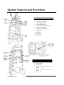
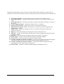
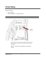
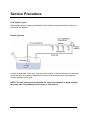
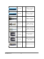
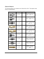
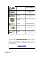
CarbonClean1000 2012 MotorVac, Inc. ZIM11-00474 Rev. 0 Table of Contents Introduction ..............................................................................................................................3 System Features and Functions ...............................................................................................4 Safety Information .....................................................................................................................6 Safety Before Starting ..............................................................................................................................6 Safety When Connecting/Disconnecting Hoses .......................................................................................7 Safety During Service...............................................................................................................................7 Initial Setup................................................................................................................................8 Service Procedures ...................................................................................................................9 Fuel System Types ...................................................................................................................................9 Manifold Connection..............................................................................................................................11 Vehicle Connection Procedure ...............................................................................................................12 Service Procedure With Manifold ..........................................................................................................13 Service Procedure With Schrader Port Connection................................................................................16 Service Procedure with Direct Connection.............................................................................................19 Fuel System Diagnostics ........................................................................................................22 Fuel System Pressure Test......................................................................................................................23 Fuel Volume Test ...................................................................................................................................23 Leakdown Test .......................................................................................................................................25 Deadhead Test ........................................................................................................................................25 Troubleshooting and Additional Help.....................................................................................26 Appendix A - Maintenance ......................................................................................................27 Maintenance Procedures.........................................................................................................................27 Maintenance Record...............................................................................................................................27 Appendix B - Replacement Parts ............................................................................................28 Replacement Parts .................................................................................................................................28 Appendix C - System Accesories ...........................................................................................29 Standard Adaptor Kit..............................................................................................................................29 Deluxe Adaptor Kit ................................................................................................................................31 2012 MotorVac, Inc. ZIM11-00474 Rev. 0 Introduction Congratulations on your selection of the MOTORVAC CarbonClean 1000. By choosing this product, you are acquiring the most technologically advanced method available for cleaning harmful fuel system contaminants from gasoline engines. This is a self-contained cleaning system, designed to connect to any gasoline engine. Once the unit is connected, it temporarily replaces the regular fuel supply with Fuel System Cleaner and Engine Decarbonizer which is a proprietary mixture of fuel and a specially formulated Cleaning Detergent. With the engine running, the unit pumps the Fuel System Cleaner and Engine Decarbonizer through the engine's fuel system. As the mixture passes through the vehicle’s fuel system, it loosens and dissolves accumulated deposits, which then pass harmlessly out through the exhaust system. Removing contaminants from the combustion chamber creates a more even burn of fuel, which improves horsepower, increases fuel economy, and reduces exhaust emissions. It is recommended that you perform the fuel system cleaning procedure on a vehicle every 15,000 miles (24,000 km) to obtain the highest fuel system efficiency. Please study this Operators Manual to become thoroughly familiar with the CarbonClean 1000 before using it. IMPORTANT The Fuel System Cleaner is designed to work EXCLUSIVELY with the MotorVac Fuel System Cleaner and Engine Decarbonizer Use of any other chemical during this process may cause operational failure of the machine and voids the manufacturer’s warranty. See warranty card for details. 3 2012 MotorVac, Inc. System Features and Functions 3 4 Carbon Clean 1000 Front and Top 2 12345678- 5 1 6 Air pressure regulator Power light indicator Ready light indicator Service complete light indicator Fuel pressure gauge Machine pressure gauge Adapter tray Drip cap 9- Inlet port 10- Inlet filter 7 8, 9, 10 13 12 14 11 Carbon Clean 1000 Back 15 11- Quick coupler 12- Service hose 13- Pressure relief/fuel system flow test button 14- Pressure relief/fuel system flow test bottle 15- Power cable 2012 MotorVac, Inc. 4 Descriptions of the gauges, control switches, and status indicators that make up the control panel are listed below. Please become familiar with these control panel features and functions before using the unit. 1. Air pressure regulator – Used to adjust the system pressure in the cleaning process. 2. Power light indicator – Illuminates when the power cables are connected to a 12VDC power source. 3. Ready light indicator – Illuminates when there is fluid in the machine indicating it is ready for the service. 4. Service complete indicator – Illuminates when the service is complete. 5. Fuel Line pressure gauge – Indicates the pressure in the vehicle’s fuel lines. 6. Machine pressure gauge– Indicates the pressure the CarbonClean 1000 is supplying to the vehicle during a service. 7. Adapter tray – Contains the adapters necessary to connect the CarbonClean 1000 to the vehicle’s fuel system. 8. Drip cap – Stops contaminants from entering the inlet filter when not in use. 9. Inlet port – Accepts can and transfers the fuel system cleaner and engine decarbonizer into the CarbonClean 1000. 10. Inlet filter – Filters debris from entering the machine and vehicle’s fuel system. 11. Quick coupler – Connects the CarbonClean 1000 to the appropriate adapter. 12. Service hose – Transfers fluid from CarbonClean 1000 to vehicle. 13. Pressure relief/fuel system flow test button – Use to relieve pressure before disconnecting the CarbonClean 1000 from the vehicle and to perform fuel pump diagnostic flow test. 14. Pressure relief/fuel system flow test bottle – Collects fluid when relieving pressure and performing a flow test on the vehicle’s fuel system. 15. Power cable – Connect to vehicle’s battery before performing a service. 5 2012 MotorVac, Inc. Safety Information Please become familiar with all safety procedures described in this chapter. IMPORTANT Failure to observe these precautions, or the improper use of equipment, could result in property damage or serious injury. Follow the safety procedures in this chapter each time the unit used. Safety Before Starting Follow these safety procedures before starting any service with the unit. Ventilate the Work Area. To avoid breathing harmful fumes and exhaust, make sure the unit is always used in a well ventilated area, away from all flames, sparks, and other ignition sources. Keep a Fire Extinguisher On Hand. Keep an approved fire extinguisher within easy reach. Check Oil and Coolant Levels. Check engine oil and coolant levels and add oil or coolant if necessary. Check Polarity. Always use proper polarity on battery posts. When connecting the unit to a battery, connect the positive (red) battery lead to the positive (+) battery terminal. Connect the negative (black) lead to the negative (-) battery terminal (11-15 VOLTS DC). Avoid Open Flames and Sparks. Keep lighted cigarettes, open flames, or other ignition sources away from the battery. Use Caution at All Times. Use safety goggles and keep hands, hair, loose clothing, and jewelry away from the battery, fan blades, belts, and other moving parts of the vehicle engine. Ensure Vehicle is safe Before beginning a service ensure the vehicle is in satisfactory condition (i.e. broken or loose fuel lines, ignition wires, battery cables, electrical wires, fuses and relays.) Relieve Fuel Tank Pressure. Before performing any fuel system service remove or loosen the fuel filler cap to the vehicle to relieve fuel tank pressure. 2012 MotorVac, Inc. 6 Safety When Connecting/Disconnecting Hoses Fuel systems maintain residual pressure in fuel lines even after the engine has been turned off. Use caution when opening any fuel line. Avoid Spills. To avoid fuel spills, wrap a clean shop cloth around fittings when connecting or disconnecting any hoses or adapters. Remove Ignition Sources. Remove all ignition sources such as lit cigarettes, matches, etc., when working with fuels and detergents. Safety During Service Follow these safety instructions whenever the unit is being operated. Consult Manufacturers Service Manual Use manufacturer’s service manual for test procedures and fuel system specifications (i.e. fuel pressure). Clean Spills Immediately. Clean up all gasoline or detergent spills immediately and make sure to use a proper container for disposal. Check All Fittings. Check all fittings and fuel lines for leaks before, during, and after performing a cleaning service. Secure Fuel Lines. Keep fuel lines away from hot manifolds and all moving components. 7 2012 MotorVac, Inc. Initial Setup Hardware Required • • Air hose nipple 9/16” (15mm) and 1” (26mm) wrenches Air Line Inlet Port Air hose inlet port Apply Teflon tape or pipe thread sealant to the threads of the air hose nipple. Screw the air hose nipple into the inlet port and tighten. (USE a 1” wrench to hold assembly to prevent from turning) 2012 MotorVac, Inc. 8 Service Procedure Fuel System Types Before beginning an exchange determine if the vehicle being serviced has a return or returnless fuel system. Return Systems A return system has 2 fuel lines, one from the fuel tank to the fuel rail and one returning to the fuel tank. A regulator maintains the correct fuel rail pressure by returning any excess fuel back to the tank. NOTE: The fuel pump must be disabled for return fuel systems as dead heading the pump can cause damage to the pump or fuel system. 9 2012 MotorVac, Inc. Returnless Fuel System A returnless fuel system has only one fuel line going from the fuel tank to the fuel rail. They can have the pressure controlled by either a mechanical pressure regulator or electronically by a PCM. Excess fuel does not pass through the fuel rail and engine compartment. 2012 MotorVac, Inc. 10 Manifold Connection The CarbonClean 1000 has been developed with a special manifold block to simplify services as well as increase diagnostic capabilities. When servicing a vehicle with a returnless fuel system you can connect the manifold assembly inline with the vehicle’s fuel line. The vehicle’s fuel system can then be disabled by simply closing the ball valve connected to the fuel pump side of the manifold. Caution: When servicing a vehicle with a returnless fuel system refer to manufacturer’s service procedures when deadheading a fuel pump to ensure the fuel pump cannot be damaged. 11 2012 MotorVac, Inc. Vehicle Connection Procedure Flammable Liquid can squirt out of pressurized lines when connecting or disconnecting. Wear Safety goggles. Obtain ZERO pressure before connecting or disconnecting any fuel lines or adaptors. Wear chemical resistant gloves when connecting or disconnecting fittings and adaptors. Wrap shop towel around pressure fittings and adaptors when disconnecting. Avoid exposure to flames, sparks, hot engine parts, and other ignition sources. Explosion or flame or exposure to flammable liquid and vapors can cause injury. 1. With the vehicle’s engine off remove the vehicle’s gas cap. 2. Connect air supply hose to air inlet adapter on the back of the CarbonClean 1000. 3. Turn pressure regulator counterclockwise until the machine pressure gauge reads zero. 4. Connect the CarbonClean1000 to the vehicle. Refer to application guide for instructions on how to properly connect to the vehicle being serviced. (www.motorvacapplicationguide.com) 5. Go to next service procedure step based on connection method. 2012 MotorVac, Inc. 12 Service Procedure With Manifold Connection 1. Open both ball valves on manifold assembly. The system is now in bypass. 2. Connect the CarbonClean 1000 supply hose to the manifold. 3. Start vehicle and inspect for any leaks at the manifold connections. 4. Note the vehicle fuel line pressure as indicated on the fuel line pressure gauge as it is required to set the machine pressure for the service. Carbon Clean 1000 diagnostic features can now be used to evaluate fuel system performance if desired. See diagnostic section 5 of this manual. 5. Run the vehicle between 1700 and 2000 rpm to warm up the engine and catalytic converter to normal operating temperature. 13 2012 MotorVac, Inc. NOTE: Use only approved chemicals Use of non approved chemicals can be a serious fire/explosion hazard Do not leave machine unattended during service. 6. Remove dust cap. Attach can by screwing it to the inlet port. Refer to directions on the can. Observe the sight glass below the inlet port to ensure the can fully empties into the machine. Leave can on during service. 7. Connect the CarbonClean 1000 battery terminals to the car’s battery. The power and ready LEDs should be illuminated. 8. Set the pressure on the CarbonClean 1000 by turning the pressure regulator clockwise slowly until the MACHINE PRESSURE GAUGE reads 5-10 psi below the pressure noted in step 4. CAUTION: Refer to application guide for vehicle specific instructions. 9. Close the fuel pump ball valve on the manifold assembly to disable the vehicle’s fuel supply. The engine is now running on the fuel system treatment. Allow the engine to run until the alarm sounds. 10. When the alarm sounds and the amber Service Complete LED is illuminated the treatment is complete. Shut off the engine. Disconnect the unit’s battery clips. CAUTION: Relieve pressure in the fuel line before disconnecting adapters. 11. The pressure can be relieved by doing the following. Turn air pressure regulator counter-clockwise until the machine pressure gauge reads zero. Press and hold the flow test button on the back of the CarbonClean 1000. This will lower the pressure by purging the excess fluid into the flow test bottle mounted on the back of the machine. 2012 MotorVac, Inc. 14 Pressure relief/fuel system flow test button 12. Remove adapters from the fuel lines and reconnect the vehicles fuel lines. Start engine and ensure there are no leaks and the lines have not become kinked or damaged. 15 2012 MotorVac, Inc. Service Procedure With Schrader Port Connection 1. Connect the CarbonClean 1000 supply hose to the adapter mounted on the Schrader port. 2. Start vehicle and inspect for any leaks at Schrader port adapter. 3. Note the vehicle fuel line pressure as indicated on the fuel line pressure gauge as it is required to set the machine pressure for the service. Carbon Clean 1000 diagnostic features can now be used to evaluate fuel system performance if desired. See diagnostic section 5 of this manual. 4. Run the vehicle between 1700 and 2000 rpm to warm up the engine and catalytic converter to normal operating temperature. 2012 MotorVac, Inc. 16 NOTE: Use only approved chemicals Use of non approved chemicals can be a serious fire/explosion hazard Do not leave machine unattended during service. 5. Remove dust cap. Attach can by screwing it to the inlet port. Refer to directions on the can. Observe the sight glass below the inlet port to ensure the can fully empties into the machine. Leave can on during service. 6. Connect the CarbonClean 1000 battery terminals to the car’s battery. The power and ready LEDs should be illuminated. 7. Set the pressure on the CarbonClean 1000 by turning the pressure regulator clockwise slowly until the MACHINE PRESSURE GAUGE reads 5-10 psi below the pressure noted in step 4. CAUTION: Refer to application guide for vehicle specific instructions. 8. Disable the fuel pump. See application guide for vehicle specific instructions. 9. When the buzzer sounds and the amber Service Complete LED is illuminated the treatment is complete. Shut off the engine. Disconnect the unit’s battery clips. Turn air pressure regulator counter-clockwise until the machine pressure gauge reads zero. CAUTION: Relieve pressure in the fuel line before disconnecting adapters. 17 2012 MotorVac, Inc. 10. The pressure can be relieved by doing the following. Turn air pressure regulator counter-clockwise until the machine pressure gauge reads zero. Press and hold the flow test button on the back of the CarbonClean 1000. This will lower the pressure by purging the excess fluid into the flow test bottle mounted on the back of the machine. Pressure relief/fuel system flow test button 11. Remove adapters from the fuel lines and reconnect the vehicles fuel lines. Start engine and ensure there are no leaks and the lines have not become kinked or damaged. 2012 MotorVac, Inc. 18 Service Procedure with Direct Connection 1. Ensure that vehicle is at proper operating temperature before performing an exchange. 2. Turn off the vehicle and connect the CarbonClean 1000 supply hose to the adapter mounted directly to the fuel line. 19 2012 MotorVac, Inc. NOTE: Use only approved chemicals Use of non approved chemicals can be a serious fire/explosion hazard Do not leave machine unattended during service. 3. Remove dust cap. Attach can by screwing it to the inlet port. Refer to directions on the can. Observe the sight glass below the inlet port to ensure the can fully empties into the machine. Leave can on during service. 4. Connect the CarbonClean 1000 battery terminals to the car’s battery. The power and ready LEDs should be illuminated. 5. Set the pressure on the CarbonClean 1000 by turning the pressure regulator clockwise slowly until the MACHINE PRESSURE GAUGE reads 5-10 psi below the pressure noted in the application guide. CAUTION: Refer to application guide for vehicle specific instructions. 6. Disable the fuel pump. See application guide for vehicle specific instructions. 7. When the buzzer sounds and the amber Service Complete LED is illuminated the treatment is complete. Shut off the engine. Disconnect the unit’s battery clips. Turn air pressure regulator counter-clockwise until the machine pressure gauge reads zero. CAUTION: Relieve pressure in the fuel line before disconnecting adapters. 2012 MotorVac, Inc. 20 8. The pressure can be relieved by doing the following. Turn air pressure regulator counter-clockwise until the machine pressure gauge reads zero. Press and hold the flow test button on the back of the CarbonClean 1000. This will lower the pressure by purging the excess fluid into the flow test bottle mounted on the back of the machine. Pressure relief/fuel system flow test button 9. Remove adapters from the fuel lines and reconnect the vehicles fuel lines. Start engine and ensure there are no leaks and the lines have not become kinked or damaged. 21 2012 MotorVac, Inc. Fuel System Diagnostics The CarbonClean 1000 has features that can be used to help diagnose fuel system problems that can result in poor engine performance. The CarbonClean 1000 is capable of performing the following tests. 1. 2. 3. 4. Fuel system pressure test Fuel system flow test Leakdown test Deadhead pump pressure test (returnless systems only, do not use on Ford) Follow the vehicle connection (section 4-4) before attempting any diagnostic tests. Note: The CarbonClean 1000 must be connected to the vehicle through either the manifold assembly or Schrader port to perform the following tests. 2012 MotorVac, Inc. 22 Fuel System Pressure Test 1. 2. 3. 4. Turn the regulator counterclockwise to set the machine pressure to zero. Open both valves on the manifold. Start the vehicle’s engine and check connections for leaks. Note the vehicle’s fuel system pressure reading from the Fuel Line Pressure gauge on the control panel of the unit. Compare this with the vehicle’s specified fuel pressure. Fuel System Flow Test Fuel system flow test button 1. 2. 3. 4. 5. Turn the regulator counterclockwise to set the machine pressure to zero. Open both valves on the manifold. Start the vehicle’s engine and check connections for leaks. While the engine is idling press and hold the flow test button for 15 seconds. Check fluid level in the pressure relief/fuel system flow test bottle. The label on the bottle has markings that correlate to a flow rate. Compare this with flow requirement chart on the following page. Note: The greatest flow rate the CarbonClean 1000 can test for at typical fuel pressure of 50 psi is 1.5 LPM. 23 2012 MotorVac, Inc. Engine Fuel Flow Requirement The chart below shows approximate fuel requirements for naturally aspirated engines based on displacement and engine speed. Engine Size liters 1.0 1.2 1.4 1.6 1.8 2.0 2.2 2.4 2.6 2.8 3.0 3.2 3.4 3.6 3.8 4.0 4.2 4.4 4.6 4.8 5.0 5.2 5.4 5.6 5.8 6.0 6.2 6.4 6.6 6.8 7.0 7.2 7.4 7.6 7.8 8.0 8.2 8.4 2012 MotorVac, Inc. 3000 0.19 0.23 0.23 0.26 0.30 0.34 0.38 0.42 0.45 0.45 0.49 0.53 0.57 0.61 0.64 0.68 0.72 0.76 0.76 0.79 0.83 0.87 0.91 0.95 0.98 1.02 1.06 1.10 1.10 1.14 1.17 1.21 1.25 1.29 1.32 1.36 1.36 1.40 4000 0.23 0.26 0.30 0.38 0.42 0.45 0.49 0.53 0.57 0.64 0.68 0.72 0.76 0.79 0.87 0.91 0.95 0.98 1.02 1.10 1.14 1.17 1.21 1.25 1.32 1.36 1.40 1.44 1.48 1.51 1.59 1.63 1.67 1.7 1.74 1.82 1.85 1.89 Engine Speed (RPM) 5000 6000 0.26 0.34 0.34 0.42 0.38 0.45 0.45 0.53 0.49 0.61 0.57 0.68 0.61 0.76 0.68 0.79 0.72 0.87 0.79 0.95 0.83 1.02 0.91 1.10 0.95 1.14 0.98 1.17 1.06 1.29 1.14 1.36 1.17 1.40 1.25 1.48 1.29 1.55 1.36 1.63 1.40 1.7 1.48 1.74 1.51 1.82 1.59 1.89 1.63 1.97 1.7 2.01 1.74 2.08 1.82 2.16 1.85 2.23 1.89 2.31 1.97 2.35 2.01 2.42 2.08 2.5 2.12 2.57 2.2 2.65 2.23 2.69 2.31 2.76 2.35 2.84 24 7000 0.38 0.45 0.57 0.64 0.72 0.79 0.87 0.95 1.02 1.10 1.17 1.25 1.32 1.36 1.51 1.59 1.67 1.74 1.82 1.89 1.97 2.04 2.12 2.2 2.27 2.35 2.42 2.5 2.61 2.69 2.76 2.84 2.91 2.99 3.07 3.14 3.22 3.29 8000 0.45 0.53 0.64 0.72 0.79 0.91 0.98 1.10 1.17 1.25 1.36 1.44 1.51 1.59 1.7 1.82 1.89 1.97 2.08 2.16 2.23 2.35 2.42 2.5 2.61 2.69 2.69 2.88 2.95 3.07 3.14 3.22 3.33 3.41 3.52 3.6 3.67 3.79 Engine Fuel Flow Requirement The following graph uses the brake specific fuel consumption (B.S.F.C.) method to estimate the fuel requirements of an engine. Brake specific fuel consumption the amount of fuel being consumed divided by the amount of power being produced. Typical values for B.S.F.C. for naturally aspirated and forced induction cars were used to estimate values indicated on the chart below. Fuel Requirement vs HP 1.7 1.6 1.5 1.4 1.3 Fuel Required (LPM) 1.2 1.1 1 0.9 0.8 0.7 0.6 Naturally Aspirated 0.5 Forced Induction 0.4 0.3 0.2 0.1 0 100 110 120 130 140 150 160 170 180 190 200 210 220 230 240 250 260 270 280 290 300 310 Horsepower Leakdown Test 1. 2. 3. 4. Turn the regulator counterclockwise to set the machine pressure to zero. Open both valves on the manifold. Start engine until the fuel line pressure stabilizes, then turn off the engine. Observe the reading on the unit’s vehicle fuel pressure gauge. If the pressure drops after 5 minutes it indicates a leak. Deadhead Test (Manifold connection only) 1. Turn the regulator counterclockwise to set the machine pressure to zero. 2. Start the engine and allow it to idle. 3. While observing the CarbonClean 1000 fuel line pressure gauge momentarily close then open the fuel rail ball valve on the manifold. This will give you the pump deadhead pressure. 25 2012 MotorVac, Inc. Troubleshooting Problem Power and/or ready lights do not illuminate Car will not shut off with fuel pump disabled Car will not run on CarbonClean 1000 Fluid leaks from the can cutter when air pressure is applied Fluid leaks from air regulator knob when canister is discharged Fluid leaks from any other location Service time is too long Service time is too short If engine struggles while running on CarbonClean 1000 Fluid takes a long time to enter the CarbonClean 1000 2012 MotorVac, Inc. Solution •if neither light illuminates, verify proper connection at battery terminal. •If only one light comes on, light is burnt out. Continue with service and contact MotorVac for replacement LED board •Verify proper relay is disabled. For some GM models it may be necessary to disable the fuel pump by alternate method. Contact technical support •Verify EFI relay was not disabled. •Verify adapter is properly connected. For most models the fuel pressure gauge should be working if a proper connection has been made. •Remove the canister of cleaning fluid to verify it has been emptied into the machine. •Disconnect fuel supply line from adapter attached to vehicle. Connect any adapter fitting to the fuel supply hose from the CarbonClean 1000, turn the regulator up to 20 psi to verify flow from the machine. •Can cutter check valve may need replacement. Leave can on during service. Contact MotorVac for replacement. •Machine was not emptied before adding a new can. Proceed with service and note length of service. Normal service time is 12-18 minutes depending on the engine. Longer than normal service time verifies the machine was already full. Inspect for leaks at next service. If problem persists contact technical support Contact technical support •Normal service time is 12-18 minutes. Longer service times can be expected on vehicles with smaller and more fuel efficient engines. If the service is excessively long turn air regulator pressure knob back to zero and disconnect fuel supply line from adapter. If vehicle continues to run, fuel pump was not disabled. •Normal service time is 12-18 minutes. Shorter service times can be expected on vehicles with larger engines. Confirm that the leak down test was SUCCESSULLY performed prior to service. If not vehicle was a leak in fuel pump check valve or regulator and needs to be repaired prior to service. •Normal service time is 12-18 minutes. If yes, pressure regulator was likely set too high allowing the regulator to return the cleaning solution back to the tank. •Slowly increase the pressure. Do not exceed the pressure specified in the application guide. •Ensure that the cans are kept at room temperature •Ensure that the pressure regulator is turned fully counterclockwise before screwing the can on •Observe the sight glass for the inlet filter, replace assembly if the filter is clogged. 26 Maintenance Maintenance Procedure 1. Clean the exterior with a plastics cleaning agent or similar product to keep the cabinet looking new. 2. Check the cabinet for dents or impact markings. Check all hoses and wires for cuts or frays. Maintenance Record Use the following table to keep a record of maintenance performed on the unit. Initial/Date CLEAN EXT. CABINET CHECK HOSES AND WIRES 27 OTHER 2012 MotorVac, Inc. Replacement Parts Carbon Clean 1000 Front and Top 3 2 4 1 1- Screw (4) 2- Air Pressure Regulator 3- LED Board 4- Gauge 5- Adapter Tray 6- Wheel 7- Hub Cap 8- Washer 9- Drip Cap 10- Splash Guard 11- Washer and Seal (10 pk) 98028760 98820311 98820307 98820220 010-5641 98064967 98064965 98071135 98820500 98820110 201352 5 6 11 7 8 9 10 14 13 12- Quick Coupler 13- Service Hose 14- Pressure relief/fuel 12 98820370 98820401 010-5642 system flow test bottle 15- Complete Internal Carbon 200-1000 Clean 1000 Assembly (Not shown) 2012 MotorVac, Inc. 28 System Accessories Standard adapter Kit The most commonly required adapters listed below are supplied with the CarbonClean 1000. Adaptor Part# Quantity Description 063-1311 1 Spring Lock Disconnect Tool - Ford 063-1360 1 Manifold Block Assembly 063-1361 1 Adapter - 7/16 Female Thread - 90° 063-1362 1 Adapter - 5/16 Female Thread - 90° 063-1364 1 Adapter - 5/16 & 3/8 Hose Barb 063-1366 1 Adapter - 5/16 Female Thread - Straight 063-1367 1 Adapter - 7/16 Female Thread -Straight 29 2012 MotorVac, Inc. 2012 MotorVac, Inc. 063-1368 1 Adapter - 8 mm Quick Connect- Male 063-1369 1 Adapter - 10 mm Quick Connect - Male 063-1370 1 Adapter - 10 mm Quick Connect - Female 063-1371 1 Adapter - Ford 9/16 Quick Connect - Male 063-1372 1 Adapter - Ford 9/16 Quick Connect - Female 98820648 1 Replacement Retaining Clip - 8 mm 98820649 1 Replacement Retaining Clip - 10 mm 98820792 1 Replacement Valve Core 30 Optional Adapters The following adapters are available for the CarbonClean 1000. The adapters listed below are sold separately. Adaptor Part# Quantity Description 063-1317 1 Adapter - Male 14mm x 1.5 063-1318 1 Adapter - Female 14mm x 1.5 063-1322 1 Adapter - Male Banjo Bolt - M10 x 1.0 063-1373 1 Adapter - Male Banjo Bolt - M12 x 1.25 063-1374 1 Adapter - Male Banjo Bolt - M12 x 1.5 063-1332 1 Adapter - Female Swivel M12 x 1.5 063-1333 1 Adapter - Male & Female Swivel - M14 x 1.5 063-1335 1 Adapter - Male & Female Swivel - M16 x 1.5 063-1339 1 Adapter - Honda Civic Quick Connect 6 mm Male 31 2012 MotorVac, Inc. 063-1375 1 Adapter - Honda Banjo 12 mm 063-1376 1 Adapter - Nissan 11mm Male 063-1377 1 Adapter - Hyundai 15 mm Male 063-1345 1 Relay - Honda Fuel Pump Disable 063-1378 1 Adapter - Hyundai 16 mm Male 063-1353 1 Fuel Nut- Honda 063-1354 1 Adapter - GM S-Bend 7/16 Female Thread ORDERING PARTS Parts for the CarbonClean 1000 may be ordered by calling MotorVac Customer Service at 1.800.841.8810. Please have your part numbers ready. www.motorvac.com [email protected] 2012 MotorVac, Inc. 32