1
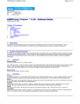
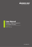
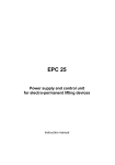
CDL-165PRO USB Wireless Transmitter and Receiver to HDMI Display Operation Manual CDL-165PRO Disclaimers The information in this manual has been carefully checked and is believed to be accurate. Cypress Technology assumes no responsibility for any infringements of patents or other rights of third parties which may result from its use. Cypress Technology assumes no responsibility for any inaccuracies that may be contained in this document. Cypress also makes no commitment to update or to keep current the information contained in this document. Cypress Technology reserves the right to make improvements to this document and/or product at any time and without notice. Copyright Notice No part of this document may be reproduced, transmitted, transcribed, stored in a retrieval system, or any of its part translated into any language or computer file, in any form or by any means - electronic, mechanical, magnetic, optical, chemical, manual, or otherwise - without express written permission and consent from Cypress Technology. © Copyright 2009 by Cypress Technology. All Rights Reserved. Version 1.0 October 2009 Trademark Acknowledgments All products or service names mentioned in this document may be trademarks of the companies with which they are associated. Safety Precautions Please read all instructions before attempting to unpack or install or operate this equipment, and before connecting the power supply. Please keep the following in mind as you unpack and install this equipment: Always follow basic safety precautions to reduce the risk of fire, electrical shock and injury to persons. To prevent fire or shock hazard, do not expose the unit to rain, moisture or install this product near water. Never spill liquid of any kind on or into this product. Never push an object of any kind into this product through module openings or empty slots, as you may damage parts. Do not attach the power supply cabling to building surfaces. Do not allow anything to rest on the power cabling or allow it to be abused by persons walking on it. To protect the equipment from overheating, do not block the slots and openings in the module housing that provide ventilation. Revision History Version No V1 V2 RDV1 VR0 VR1 Date 20091119 20101022 20101126 20110526 20110708 Summary of Change Preliminary Release Software Installation Cancel Firmware Update Add 9.1 Delete 10.2 Table of Contents 1. Introduction 1 2. Applications 1 3. Package Contents 1 4. System Requirements 1 5. Features 2 6. Specifications 2 7. Operation Controls and Functions 3 7.1 Transmitter 3 7.2 Receiver 3 7.2.1 Front Panel 3 7.2.2 Back Panel 4 8. Software Installation 5 9. Using Wireless USB Manager 8 9.1 Connecting Wireless USB Manager 8 9.2 Select Connection Rules item 9 9.3 System Association 9 9.4 Device Connection 10. 10 Using DisplayLink Manager 11 10.1 Using DisplayLink Manager 11 11. Uninstall the Device Driver 15 12. Connection and Installation 16 13. Troubleshooting 17 14. Acronyms 18 1. Introduction Today people are spending more of their time around technology, especially for entertainment purposes, and often encounter problems. People spend a lot of their watching Internet TV (HULU for instance is a popular source for internet TV and movies However when the Internet TV viewer requires a larger viewing screen for a more immersive experience they then have to go through the hassle of connecting multiple cables, or working with wireless devices that fail to impress us on their quality. Well our “USB wireless transmitter and receiver to HDMI display” can allow you to view any PC information on a compatible TV with a wired like experience. An additional feature of this product is that it includes extra USB ports allowing it to perform KVM operations next to the TV, which is an added bonus for those of us who are multi-taskers. 2. Applications Wirelessly send Audio and Video from your PC to an HDTV Watch Internet TV on big screen, wirelessly 3. Package Contents USB Wireless Transmitter USB Wireless Receiver 5V DC power adaptor User Manual Driver CD 4. System Requirements System Hardware Requirements: 2.4 GHz single core CPU with at least 1GB RAM for optimal performance Operating Systems: Windows XP Home or Professional 32 bits SP2 Windows Vista 32 bits Windows 7 USB Port Extension: An available USB 2.0 port with USB to mini USB cable It is suggested to upgrade your systems graphics drivers, Display Link software and the mother boards chip set driver to their latest version 1 5. Features Worldwide Band Groups 1,3,4 and 6 Supports HDMI & VGA outputs 16/32-bit Color for high-quality images HD resolution up to 1920 x 1080 Has a broadcast range of 10 meters Speed up to 150Mb/s HDMI and RGB display connectivity EDID selection with switch for VGA or HDMI output Secure and easy to use 6. Specifications Input Port Output Ports Extender Ports Power Supply ESD Protection 1 x Mini USB 1 x HDMI, 1 x D-Sub 15pin, 3.5Φ phone jack 2 x USB Hubs (A type) 5V DC/2.6A (US/EU standards, CE/FCC/UL certified) Dimensions (mm) Transmitter: 81(W) x 25(D) x 11(H) Receiver: 90(W) x 120(D) x 25(H) Transmitter: 22 Receiver: 120 Transmitter: Plastic Receiver: Plastic Transmitter: Black Receiver: Metal Black Receiver: 8W 0˚C ~ 40˚C / 32˚F ~ 104˚F -20˚C ~ 60˚C / -4˚F ~ 140˚F 20~90% RH (non-condensing) Weight(g) Chassis Material Silkscreen Color Power Consumption Operating Temperature Storage Temperature Relative Humidity Human body model: ± 8kV (air-gap discharge) ± 4kV (contact discharge) 2 7. Operation Controls and Functions The following sections describe the hardware components of the unit and include a step by step installation guide and other suggested settings. 7.1Transmitter Connect the wireless USB dongle to a PC or Laptop to deliver fast and reliable media through the use of Ultra Wide Band (UWB) technology. The LED will illuminate when PC or Laptop has successully detect the device and when the LED is blinking it means data is been transmit to receiver. 7.2Receiver 7.2.1 Front Panel 1 2 3 ① HDMI OUT: Connect the HDMI output to the HDMI display. ② AUDIO OUT: Connect the audio output to the speaker or AVR. ③ VGA OUT: Connect the VGA output to the VGA monitor. Note: HDMI and VGA can output at the same time. 3 7.2.2 Back Panel 2 1 3 4 5 6 Power: This slot is where the user plugs in the 5V DC power supply of this unit before connecting the adaptor to an AC wall outlet. ② Link LED: When the LED illuminate it shows that the device has successfully detected the transmitter and when it blink it means the device is receiving transmitter's signals. CABLE ASSOC.: This slot is where the user connects a USB cable to the PC ③ or Laptop USB port for ID association when first using the system and later on when establishing a connection with the Transmitter. ④ EDID control switch: The default setting for this switch is HDMI, leave the switch here as long as the connected display is compatible. When the EDID control is switched from HDMI to VGA the unit will detect the sources EDID and record it. Turn off in order to use the built in EDID. ⑤ USB Port: These ports allow the receiver to act like a USB hub, allowing you to connect an External Hard Drive, Keyboard or Mouse. Note: Before removing the USB device, the user must follow the USB devices hardware removal procedure. Failure to do so will cause the system to crash. ⑥ Mini USB IN: This port, when connecting to USB port of your PC via USB cable, supports mirror or video extension of your PC content on your HDMI display. When connected it will override and replace the wireless USB connection between TX and RX and the unit then works as a wired USB to HDMI Converter. ① 4 8. Software Installation The following sections list the procedures to follow when installing the USB to HDMI and USB device drivers. Insert the provided CD into your CD-ROM drive, then begin the Wireless USB Install Disc and follow the below steps to install the driver. Step 1: Click Install drivers and application. Step 2: Click “Continue” to start the setup. Step 3: Click "Next" to continue the set up. 5 Step 4: Click “I accept the terms of the License Agreement” and go to the Next page. Step 5: Click “Finish” to complete the installation. The installation process may take a little time, please be patient while the system is running. 6 Step 6: Click “I accept the terms of the License Agreement” and go to the Next page. The installation process may take a little time, please be patient while the system is running. Step 7: When all three software are being instally successfully with three tick show on the window, Click “Close” to finish installing. 7 Step 8: Click "exit" to exit the installer dialogue and restart the computer. Notes: At this point, users should power-on and connect the receiver to the display. 9. Using Wireless USB Manager 9.1 Connecting Wireless USB Manager Connect the transmitter on to the source device (PC/NB) and click on the "Start" from the Desktop. Select Alereon from All Program and double click on "Wireless USB Manager". 8 9.2 Select Connection Rules item To connect a device for the first time the user must form an association ensuring secure communications. 9.3 System Association Enter pin code to associate with your computer. Pin Code is located on FCC/CE sticker, placed on both the device's bottom and outside package. 9 Association is successful 9.4 Device Connection 10 10. Using DisplayLink Manager 10.1 Using DisplayLink Manager After the driver is installed, a utility (DisplayLink Manager) will automatically appear in the system tray. The utility allows you to quickly change the settings and resolution for DisplayLink Manager. Right click on the icon will bring out the context menu. Screen Resolution: Select the screen resolution (available only in extended mode). Note: When the display has a built in EDID the screen will show the displays resolution, if no EDID is present the screen has the following resolution (see below image) 11 Color Quality: Select the screen color quality (available only in extended mode). Screen Rotation: Rotate the screen on the additional monitor by 90, 180 or 270 degrees. Extend to: Reposition the extended screen to the top, bottom, left or right of the primary display. 12 Extend: Set the DisplayLink Manager to Extended mode. Set as Main Monitor: Set the monitor to be the main monitor. Notebook Monitor off: Set the PC/notebook's monitor off. 13 Mirror: Set the DisplayLink Manager to Mirror mode. You can see the same desktop image on the additional monitor. Off: Disable the DisplayLink Manager on the system. Advanced: Opening the Display Properties will allow you to adjust the resolution, color quality, position and refresh rate. 14 11. Uninstall the Device Driver Follow the steps below to uninstall the Multi View driver. Step 1: Open the Control Panel: Start → Control Panel → Add or Remove Programs. Step 2: Select USB-VGA-HDMI DisplayLink Adapter and click Remove. Step 3: Click Yes to confirm the removal. Step 4: Click Yes to restart your computer. 15 12. Connection and Installation or or PC Transmitter Keybord NB or or Mouse HDD Flash CDL-165PRO HDMI Monitor or TV/Monitor 16 Amplifier Speaker 13. Troubleshooting Situation Check Point The device driver has been installed, but the DisplayLink Manager is not working 1. Make sure you restart your computer after the driver installation. 2. Check all the connectors are plugged in correctly. 3. Make sure the USB port that you are using is USB 2.0. 4. Check the additional monitor is connected correctly and the power is on. 5. Make sure the operating system, the DisplayLink Manager is compatible with Windows XP,Windows 7 and Vista (32bit). 6. Try a different USB 2.0 or computer. 7. Check USB cable’s specification. DVD player is not working when moved to the extended display 1. Try to run another software player if possible, disable the overlay function. The mouse does not move passed the right side during extended desk top mode. 1. Check the display settings and make sure that your display number 2 is on the right side of display number 1. 17 A Acronyms Acronym Complete Term EDID Extended Display Identification Data HDMI High-Definition Multimedia Interface VGA Video Graphics Array 18 19 CYPRESS TECHNOLOGY CO., LTD. Home page: http://www.cypress.com.tw 20100114 MPM-CDL165PRO