1
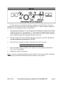
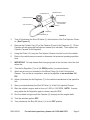
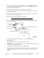
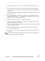
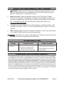
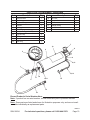
FUEL Injection CANISTER
CLEANER
95834
Set up and Operating Instructions
Visit our website at: http://www.harborfreight.com
Read this material before using this product.
Failure to do so can result in serious injury.
Save this manual.
Copyright© 2007 by Harbor Freight Tools®. All rights reserved. No portion of this manual or any artwork
contained herein may be reproduced in any shape or form without the express written consent of
Harbor Freight Tools. Diagrams within this manual may not be drawn proportionally. Due to continuing
improvements, actual product may differ slightly from the product described herein. Tools required for
assembly and service may not be included.
For technical questions or replacement parts, please call 1-800-444-3353.
Cover Revised 08i, 09h
Specifications
Air Regulator Type
Dial Type / Push Lock
Minimum/Maximum Working Pressure
5 PSI / 100 PSI
Air Regulator Dimensions
2-5/8” Long x 1-9/16” Wide x 3-1/2” High
Gauge Dimensions
4” Diameter x 1-3/4” Thick
Gauge Markings
0 <-> 150 PSI / 0 <-> 1000 kPa
Application
Fuel-injected Gasoline Engines only
Hose Pressure Capacity
250 PSI
Hose Dimensions
71-3/4” Long x 3/8” Diameter
Chain Hook Length
9” Long
Canister Capacity
16 Fluid Ounces
Net Weight
4.45 Pounds
SAVE THIS MANUAL
You will need this manual for the safety warnings and precautions, assembly,
operating, inspection, maintenance and cleaning procedures, parts list and assembly
diagram. Keep your invoice with this manual. Write the invoice number on the inside of
the front cover. Write the product’s serial number in the back of the manual near the assembly diagram, or write month and year of purchase if product has no number. Keep
this manual and invoice in a safe and dry place for future reference.
GENERAL SAFETY RULES
WARNING!
READ AND UNDERSTAND ALL INSTRUCTIONS
Failure to follow all instructions listed below may result in
electric shock, fire, and/or serious injury.
SAVE THESE INSTRUCTIONS
1.
Keep your work area clean and well lit. Cluttered benches and dark areas invite
accidents.
2.
Stay alert. Watch what you are doing, and use common sense when operating this tool. Do not use this tool while tired or under the influence of drugs,
alcohol, or medication. A moment of inattention while operating tools may result
in serious personal injury.
3.
Do not overreach when using this tool. Keep proper footing and balance at
all times. Proper footing and balance enables better control in unexpected situations.
SKU 95834
For technical questions, please call 1-800-444-3353.
Page 2
4.
Use safety equipment when using this tool. Wear ANSI-approved safety
goggles and a NIOSH-approved respirator.
5.
Do not force this tool. Use the correct tool for your application. The correct
tool will do the job better and safer at the rate for which it is designed. Do not force
the product and do not use this product for a purpose for which it is not intended.
6.
Store idle tools out of reach of children and other untrained persons. Tools
are dangerous in the hands of untrained users.
7.
Maintain this tool with care. Keep this tool clean. Properly maintained tools
are less likely to malfunction and are easier to control. Do not use a damaged tool.
Tag damaged tools “Do not use” until repaired.
8.
Check for misalignment or binding of moving parts, breakage of parts, and
any other condition that may affect this tool’s operation. If damaged, have
the tool serviced before using. Many accidents are caused by poorly maintained
tools.
9.
Use only accessories that are recommended by the manufacturer for your
model. Accessories that may be suitable for one tool may become hazardous
when used on another tool.
10. Tool service must be performed only by qualified repair personnel. Service or
maintenance performed by unqualified personnel could result in a risk of injury.
11. When servicing a tool, use only identical replacement parts. Follow instructions in the “Inspection, Maintenance, And Cleaning” section of this manual.
Use of unauthorized parts or failure to follow maintenance instructions may create
a risk of injury.
12. Maintain labels and nameplates on the this tool. These carry important information. If unreadable or missing, contact Harbor Freight Tools for a replacement.
13. Do not operate the Fuel Injection Cleaner in a closed area or in a poorly ventilated area. When a vehicle’s engine is running, the engine produces carbon
monoxide, a colorless, odorless, toxic fume that, when inhaled, can cause
serious personal injury or death. Whenever possible, use a carbon monoxide
detector (not included) to detect excessive carbon monoxide fumes in the work
area and in the surrounding area.
14. Release fuel system pressure before servicing fuel system components.
15. Firmly tighten all connections before cleaning injectors. Fuel leakage can
cause a fire.
16. To avoid spilling fuel on the engine, wrap a shop towel around the pressure
tap fittings when connecting and disconnecting adapters. Pressurized fuel
SKU 95834
For technical questions, please call 1-800-444-3353.
Page 3
can create a fire hazard. Dispose of the shop towel properly. Be aware that gasoline fumes remain within the tool after use, and can create an explosion hazard.
17. Make sure to keep dirt and debris out of the fuel system when cleaning.
18. Prior to servicing injectors, make sure to read and understand all instructions and safety precautions as outlined in the vehicle manufacturer’s service manual.
19. Replace the injector’s O-rings whenever injectors are removed. Never exceed
recommended pressures when cleaning fuel injectors.
20. Use the Fuel Injection Cleaner only on fuel injected gasoline engines.
21. Protect painted surfaces from fuel or cleaner fluid spills.
22. Keep tools, electrical cords, and hoses away from moving engine parts.
23. Wrap a shop towel around the fitting when removing the cleaner assembly
Hose. Residual line pressure may spray a small amount of cleaner fluid.
24. Observe normal precautions for working with flammable liquids. No smoking, open flames, electrical sparks, etc. Have a Class B fire extinguisher
available while working on fuel injection systems.
25. Power using compressed air only. Never use bottled gas as a power source.
26. Do not exceed 100 PSI operating pressure.
27. Do not apply pressure to the canister until ready to use.
Unpacking
When unpacking, check to make sure that the item is intact and undamaged. If
any parts are missing or broken, please call Harbor Freight Tools at the number shown
on the cover of this manual as soon as possible.
SKU 95834
For technical questions, please call 1-800-444-3353.
Page 4
Setup
For best service you should incorporate a regulator and inline filter on the compressor end of the hose, as shown in the diagram above. Hoses, couplers, regulators,
and filters are all available at Harbor Freight Tools.
1.
You will need to prepare a 1/4” air connector (not included) to connect to the Elbow
Fitting (8) on the tool. First, wrap the 1/4” air connector with pipe thread seal tape
before threading it into the Elbow Fitting. Connect the 3/8” ID Air Source Hose to a
quick connect coupler (not included), and then to the tool.
2.
Set the air pressure on the regulator near the compressor to 90 PSI. Do not exceed the maximum air pressure of 100 PSI.
3.
Check the air connection for leaks. Disconnect from the air source.
TO CLEAN THE FUEL INJECTORS
1.
Run the vehicle’s engine outside until it reaches normal operating temperature.
Then, shut off the engine.
2.
Disable the vehicle’s fuel pump.
Note: It is best to unplug the fuel pump at the fuel tank. On some vehicles, pulling the
fuel pump fuse also disables the ignition system or fuel injectors.
SKU 95834
For technical questions, please call 1-800-444-3353.
Page 5
CYLINDER CAP (10)
AIR REGULATOR (7)
ELBOW FITTING (8)
PRESSURE GAUGE (5)
AIR HOSE COUPLER
(NOT INCLUDED)
SHUT OFF VALVE (1)
CHAIN (12)
CANISTER (6)
COUPLER SOCKET (15)
FIGURE A
3.
Turn off (clockwise) the Shut Off Valve (1) at the bottom of the Fuel Injection Cleaner. (See Figure A.)
4.
Remove the Cylinder Cap (10) of the Canister (6) and its Air Regulator (7). Fill the
Canister with an approved fuel injection cleaner (not included). Then replace the
Cylinder Cap and its Air Regulator.
5.
Using the Chain (12), hang the Fuel Injector Cleaner from the hood of the vehicle.
6.
Refer to the vehicle service manual to determine fuel pressure operating specifications.
7.
IMPORTANT: To keep cleaner fluid from going back to the fuel tank, block the fuel
return line.
8.
Turn the Air Regulator (7) to its full OPEN position (counterclockwise).
9.
Attach an air hose (not included) to the Elbow Fitting (8) of the Fuel Injection
Cleaner. Turn on the air compressor, and set its regulator at no more than 100
PSI.
10. Adjust (clockwise) the Air Regulator (7) to the vehicle manufacturer’s fuel specification.
11. Open (counterclockwise) the Shut Off Valve (1) of the Fuel Injection Cleaner.
12. Start the vehicle’s engine, and let it run at 1,000 to 1,500 RPM. NOTE: If necessary, adjust the Air Regulator again to obtain a smooth RPM.
13. Run the vehicle’s engine until the Canister (6) is empty and the engine stalls.
14. Turn the vehicle’s ignition OFF.
15. Turn (clockwise) the Shut Off Valve (1) to its full OFF position.
SKU 95834
For technical questions, please call 1-800-444-3353.
Page 6
16. Turn off the air compressor. Disconnect the air hose from the Elbow Fitting (8).
Then turn (counterclockwise) the Air Regulator (7) to its full OPEN position to release pressure in the Canister (6).
17. Disconnect the Coupler Socket (15) from the vehicle’s fuel port.
18. Remove the block on the vehicle’s fuel return line or, if applicable, reconnect the
vehicle’s fuel return line.
19. Store the Fuel Injection Cleaner in a clean, dry, safe location out of reach of children and other unauthorized people.
20. Start the vehicle’s engine, and check for fuel leaks.
TO DECARBONIZE THE ENGINE CYLINDERS
1.
Run the vehicle’s engine until the engine reaches normal operating temperature.
Then, shut off the engine.
AIR REGULATOR (7)
ELBOW FITTING (8)
CANISTER (6)
MANIFOLD
VACUUM
PORT
THROTTLE BODY OR CARBURETOR
PRESSURE GAUGE (5)
SHUT OFF VALVE (1)
INTAKE MANIFOLD
DECARBONIZINE FITTING (21)
ENGINE
FIGURE B
2.
Turn (counterclockwise) the Air Regulator (7) to its full OPEN position.
(See Figure B.)
3.
Connect the Coupler Socket (15) to the vehicle’s fuel port.
4.
IMPORTANT: Leave the Elbow Fitting (8) open. For this procedure, DO NOT connect an air hose to the Elbow Fitting.
5.
Turn (clockwise) the Shut Off Valve (1) to its OFF position.
6.
Remove the top of the Canister (6) and its Air Regulator (7). Fill the Canister with
an approved decarbonizer (not included). Then, replace the Canister and Air
Regulator.
SKU 95834
For technical questions, please call 1-800-444-3353.
Page 7
7.
Connect the Canister Hose (16) to the provided Decarbonizing Fitting (not included).
8.
Locate a manifold vacuum port on the vehicle’s engine (NOT a ported vacuum)
near the throttle body or carburetor. (This will distribute the decarbonizing solution
more evenly.)
9.
Connect the Decarbonizing Fitting (not included) to the manifold vacuum port on
the vehicle’s engine.
10. Start the vehicle’s engine. Manually increase throttle to 1,500 RPM while slowly
opening the Shut Off Valve (1). The engine will run rough and RPM will decrease.
DO NOT continue to manually increase RPM.
11. When the Canister (6) is empty, turn off the vehicle’s engine.
12. Remove the Decarbonizing Fitting (not included) from the vehicle’s engine. Then,
reconnect the engine’s vacuum hose.
13. Store the Fuel Ignition Cleaner in a clean, dry, safe location out of reach of children
and other unauthorized people.
14. Allow the vehicle to set (turned off) for about 30 minutes to allow the solution to
work on soft carbon deposits.
15. Test drive the vehicle for at least 15 miles to flush loosened carbon deposits out of
the system.
Note: Until the system is flushed out, the vehicle may start hard, run rough, and heavy
white smoke may come out of the tailpipe.
REV 07f
SKU 95834
For technical questions, please call 1-800-444-3353.
Page 8
INSPECTION, MAINTENANCE, AND CLEANING
1.
WARNING! Make sure the Fuel Ignition Cleaner is disconnected from an engine and all pressure has been released from the tool before performing any inspection, maintenance, or cleaning procedures.
2.
Before each use, inspect the general condition of the Fuel Ignition Cleaner.
Check for loose screws, misalignment or binding of moving parts, cracked or broken parts, damaged hose, and any other condition that may affect its safe operation. If a problem occurs, have the problem corrected before further use.
Do not use damaged tools.
3.
To clean, use a clean, damp cloth and mild detergent to clean the exterior of the
Fuel Ignition Cleaner. Then dry. Do not immersed any part in liquid. Do not use
solvents.
4.
When storing, always store the Fuel Ignition Cleaner in a clean, dry, safe location
out of reach of children and other unauthorized people.
CAUTION! All maintenance, service, and repairs not mentioned in this manual must
only be performed by a qualified service technician.
Troubleshooting
Problem
Possible Causes
Fuel Injection Cleaner
does not work.
1. Loose connection(s).
2. Improper air compressor PSI.
3. Improper Air Regulator PSI.
4. Canister empty of cleaning fluid.
Probable Solutions
1.
2.
3.
4.
Recheck all connections.
Set air compressor to proper PSI.
Set Air Regulator to proper PSI.
Refill Canister.
PLEASE READ THE FOLLOWING carefully
The manufacturer and/or distributor has provided the parts list and assembly diagram in this manual as a reference tool only. Neither the manufacturer
or distributor makes any representation or warranty of any kind to the buyer
that he or she is qualified to make any repairs to the product, or that he or
she is qualified to replace any parts of the product. In fact, the manufacturer
and/or distributor expressly states that all repairs and parts replacements
should be undertaken by certified and licensed technicians, and not by the
buyer. The buyer assumes all risk and liability arising out of his or her repairs
to the original product or replacement parts thereto, or arising out of his or
her installation of replacement parts thereto.
SKU 95834
For technical questions, please call 1-800-444-3353.
Page 9
PARTS LIST & ASSEMBLY DIAGRAM
Part
Description
Q’ty
Part
Description
Q’ty
1
Shut Off Valve
1
14
“S” Hook
1
2
Tee Fitting
1
15
Coupler Socket
1
5
Pressure Gauge
1
16
Hose
1
6
Canister
1
17
Straight Fitting
1
7
Air Regulator
1
18
Check Valve
1
8
Elbow Fitting
1
19
Decal
1
9
Straight Fitting (1/4” NPT)
1
10
Cylinder Cap
2
11
O-Ring
2
12
Chain
1
13
Split Ring
1
7
19
8
6
5
9
10,11
1
12, 13
17
18
2
10,11
14
15
16
Record Product’s Serial Number Here:
Note: If product has no serial number, record month and year of purchase instead.
Note: Some parts are listed and shown for illustration purposes only, and are not available individually as replacement parts.
REV 07f
SKU 95834
For technical questions, please call 1-800-444-3353.
Page 10
LIMITED 90 DAY WARRANTY
Harbor Freight Tools Co. makes every effort to assure that its products meet high
quality and durability standards, and warrants to the original purchaser that this product is free from defects in materials and workmanship for the period of 90 days from
the date of purchase. This warranty does not apply to damage due directly or indirectly,
to misuse, abuse, negligence or accidents, repairs or alterations outside our facilities,
criminal activity, improper installation, normal wear and tear, or to lack of maintenance.
We shall in no event be liable for death, injuries to persons or property, or for incidental,
contingent, special or consequential damages arising from the use of our product. Some
states do not allow the exclusion or limitation of incidental or consequential damages, so
the above limitation of exclusion may not apply to you. This warranty is expressly in lieu of all other warranties, express or implied, including the
warranties of merchantability and fitness.
To take advantage of this warranty, the product or part must be returned to us with
transportation charges prepaid. Proof of purchase date and an explanation of the complaint must accompany the merchandise. If our inspection verifies the defect, we will either repair or replace the product at our election or we may elect to refund the purchase
price if we cannot readily and quickly provide you with a replacement. We will return repaired products at our expense, but if we determine there is no defect, or that the defect
resulted from causes not within the scope of our warranty, then you must bear the cost
of returning the product.
This warranty gives you specific legal rights and you may also have other rights
which vary from state to state.
3491 Mission Oaks Blvd. • PO Box 6009 • Camarillo, CA 93011 • (800) 444-3353
SKU 95834
For technical questions, please call 1-800-444-3353.
Page 11