1
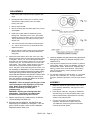
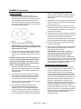
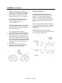
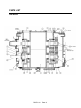
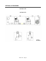
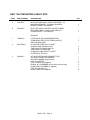
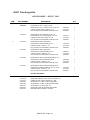
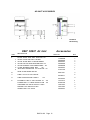
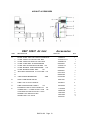
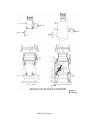
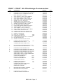
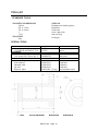
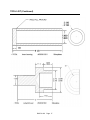
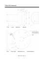
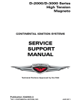
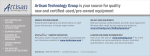
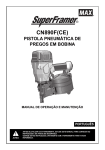
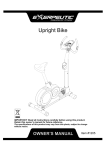
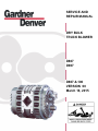
SERVICE AND
REPAIR MANUAL
DRY BULK
TRUCK BLOWER
D807
D907
D807-6-100
VERSION 00
March 16, 2015
Drum-6-10
Page 1
Table of Contents
Page
Torque Requirements............................................................................ 2
Oil Requirement .................................................................................... 2
Clearances ........................................................................................... 2
Disassembly Procedures ....................................................................... 3
Assembly Procedures ........................................................................... 3
Parts List .............................................................................................. 6
Optional Accessories............................................................................. 8
Tool List................................................................................................ 16
Safety ................................................................................................... 19
WARRANTY
The seller warrants the goods sold hereunder against defects
in workmanship or materials under normal and proper
installation for a period of twelve (12) months from the date of
delivery. BUYER’S SOLE AND EXCLUSIVE REMEDY
UNDER THIS WARRANTY IS FOR THE REPAIR OR
REPLACEMENT AT SELLER’S OPTION, WITHOUT
CHARGE TO BUYER EXCEPT FOR SHIPPING
EXPENSES, AT THE OFFICE OF THE SELLER IN
LOUISVILLE, KY, OF ANY PART WHICH HAS PROVEN TO
BE DEFECTIVE AT THE TIME IT WAS DELIVERED. ANY
GOODS UNDER WARRANTY MUST BE DELIVERED TO
THE SELLER’S OFFICE FOR INSPECTION BY THE
SELLER AND, IF ANY SUCH GOODS ARE FOUND TO BE
DEFECTIVE, FOR REPAIR OR REPLACEMENT. ALL
FREIGHT AND EXPENSES OF SHIPMENT TO AND FROM
SELLER'S OFFICE SHALL BE BORNE BY THE BUYER.
THE SELLER IS NOT RESPONSIBLE FOR ANY
EXPENSES OF ANY NATURE INCURRED FOR ANY
REPAIRS TO ALTERATIONS MADE BY OTHERS TO THE
GOODS OR ANY OTHER EQUIPMENT WITHOUT THE
PREVIOUS WRITTEN CONSENT OF THE SELLER.
SHOULD THE GOODS BE PARTIALLY OR FULLY
INSTALLED, ALTERED, STRIPPED, REPAIRED,
SERVICED, OR MAINTAINED BY ANY PERSON OTHER
THAN AUTHORIZED AGENTS AND EMPLOYEES OF THE
SELLER, WITHOUT THE PREVIOUS CONSENT OF THE
SELLER, OR MISUSED IN ANY WAY, THIS WARRANTY
SHALL BE VOID. THIS WARRANTY CONSTITUTES THE
ONLY WARRANTY BY THE SELLER OF THE GOODS AND
IS IN LIEU OF ALL OTHER WARRANTIES, EXPRESS OR
IMPLIED, INCLUDING, BUT NOT LIMITED TO,
WARRANTIES OF MERCHANTABILITY OR WARRANTIES
OF FITNESS FOR A PARTICULAR PURPOSE. IN NO
EVENT SHALL SELLER BE LIABLE FOR BUYER’S
ATTORNEY’S FEES.
NO CONSEQUENTIAL DAMAGES: UNDER NO
CIRCUMSTANCES SHALL THE SELLER BE LIABLE FOR
(A) ANY DAMAGE, INJURY, BREAKAGE OR LOSS OF ANY
KIND WHATSOEVER, (B) ANY LOSS OF INCOME, OR (C)
ANY CONSEQUENTIAL LOSS. NO TORT LIABILITY:
D807-6-100
SELLER DISCLAIMS ANY LIABILITY FOR CLAIMS BASED
ON SELLER’S NEGLIGENCE OR STRICT LIABILITY IN
TORT. PARTS: This warranty and all disclaimers and
limitations of liability shall apply to all parts sold to buyer.
TRAINING AND SUPERVISION: The buyer hereby assumes
the affirmative duty to properly educate, instruct and
supervise its employees and all others, except employees of
the Seller, in the safe, proper use and operation of the goods.
The Buyer agrees to indemnify the Seller for any damages
paid by the latter as a result of the Buyer’s failure to perform
this affirmative duty. The goods are not designed or intended
for use with every substance. If the material which the buyer
contemplates transferring with the goods has corrosive or
polymerizing or other properties which may result in
unsatisfactory or dangerous operations, the Seller has no
liability or responsibility for performance of the goods.
RETURN OF GOODS: No goods supplied may be returned
to the Seller for credit without the Seller’s prior written
authorization before transportation thereof commences and
in such cases transportation must be prepaid and the Buyer’s
name, address, original order number and the Seller’s invoice
number must be clearly marked on the shipping tag.
If any goods are returned to the Seller for repair or under
warranty and no instructions are received within two months
after Seller receives the goods for repair or sends notice to
Buyer of the disallowance of a warranty claim, the Seller
reserves the right to scrap the goods returned, and no
subsequent claim for any costs or losses will be accepted.
APPLICABLE LAW AND VENUE: The rights and obligations
of the parties hereunder shall be governed in all respects,
including all questions of construction and performance of
this order, by the laws of Kentucky. All disputes concerning
this order shall be resolved in an appropriate state or federal
court located in Louisville, Kentucky.
MODIFICATION OR RESCISSION: This warranty can only
be modified or rescinded by a written agreement signed by
an officer of both the Buyer and the Seller.
GARDNER DENVER, INC., Louisville, Kentucky (502) 2666677
Page 1
REPAIR PARTS ORDERING
When ordering repair parts, give the following information:
·
Complete model number and serial number of unit
·
Description of par and part number shown on parts list. (page 6 and 7)
TORQUE REQUIREMENTS
·
·
M10 X 1.5 Screws
M14 x 2 Screws
29 ft. lbs. (40 Nm)
80 ft. lbs. (110 Nm)
OIL REQUIREMENTS
Fill both Non-Drive End and Drive End of blower with oil to the center of oil level sight glasses, while machine is not
running.
·
·
Standard Oil:
Food Grade Oil:
AEON PD Synthetic Lubricant is supplied with machine, capacity as above.
AEON PD-FG Food Grade Synthetic Lubricant
HORIZONTAL AIR FLOW
approx. 25 oz. (.0.8 qt.)
approx. 15 oz. (.0.5 qt.)
Non-Drive End
Drive End
VERTICAL AIR FLOW
approx. 52 ox. (1.6 qt.)
approx. 31 ox. (1.0 qt.)
CAUTION: Mixing or incorrect oil can result in gear and bearing failure.
NOTE:
Food grade oil does not have the longevity of synthetic oil. More frequent oil changes are
necessary based upon duty cycles) to prevent premature bearing wear.
NOTE:
Change oil ever 500 hours, twice a year or as necessary (based upon duty cycle) to
Prevent premature bearing wear.
CLEARANCES
(Dimensions in Thousandths of an inch)
Blower clearance specifications
Model
Gear End
Free End
Interlobe
Tip-Dowel
Tip-Port
D807
5 – 11
12 – 18
13 – 17
6 - 10
9 - 13
D907
5 - 11
14 - 20
13 - 17
6 - 10
9 - 13
D807-6-100
Page 2
DISASSEMBLY
8.
1.
Drain oil from both covers by removing magnetic drain
plugs.
2.
Mark all parts with a center punch so that they can be
reassembled in same position (rotors, and plates,
housing and cover).
3.
Remove key from shaft.
4.
Remove oil slinger (20) and retainer plates (14) on drive
end sideplate.
5.
Install a pair of gear plates p/n 530061204, to each
bearing bore. Alternately turn two 2-ton, 2-jaw pullers
(CG240) to remove end plate *4) from rotor housing (3).
Tap out roller bearings (10), seals (12) and (51), seal
retainer (219.
6.
Turn unit around and remove bolts and washers (26 &
27). Tap non-drive end cover (7) with mallet to break
sealant and remove.
7.
Remove bolts and washers (29 & 25) using 7/8” socket.
Replace bolts in end of rotor to protect threads when
using puller.
Position the blower with the driven gear on the right. Align
the timing gears for pulling by first matching the timing marks
on the gears. See Fig. 1A. Turn the drive gear clockwise
three teeth and mark a matching reference line on each gear
as shown in Fig. 1B. The rotor lobes are now in their most
open position. Using a puller, CG240, the driven gear (left
hand helix) may now be removed without jamming the
rotors. This gear is in two parts—the gear rim and hub. It is
not necessary to disassemble. Do not allow the gears
to move from the matched reference line while pulling.
Use a light rocking motion while pulling the gear to
ensure that the lobes have not jammed. Remove drive
and non-drive gears. It is necessary to remove keys
from rotor shafts so that the gear plates can be fitted
for removing rotors from sideplates.
WARNING: Failure to properly pull the gears could
result in damage to rotor keyways or a bent rotor
shaft. Rotors must be free when pulling. If
machine is locked up, pull both gears
simultaneously.
WARNING: Discard gear retaining bolts after
disassembly. These bolts are installed with
permanent Loctite and may fail if reused.
9.
Remove cap screws (61), washers (62), oil deflector
(15) and bearing lock plates (14).
11. Carefully separate end plate from housing and tap out
bearings (9), lip seals (12), labyrinth seals (51) and
retainers (219).
12. Clean all parts for inspection if there has been any metal to
metal contact. Please consult your distributor or factory for
full specification sheets. NOTE: Rotors, sideplates, body,
bearing, journals can be remanufactured. Inspect timing
gears for wear and pitting. Factory bearings and seals
should be installed.
13. It is important to determine cause of failure, i.e., over-speed,
pressure, lack of lubrication, etc., as it may necessitate
changes in operational procedure, to ensure longer machine
life.
ASSEMBLY
1.
Make sure all parts are clean and free of any nicks or
burrs caused by disassembly. See page 10 for seal
pressing tools.
2.
Press labyrinth seals (51), using tool p/n 530061202,
with step facing up, into both end plates (4&5). Press
retainer downward with cupped side down until firmly
seated on top of labyrinth seal.
3.
Coat O.D. of lip seals (12) with Permatex #2 or
equivalent, and press into end plates, using tool
p/n 530061203, with lip facing upward until seated.
Lubricate lip seal with grease.
10. Bolt gear plate p/n 53006124, with M6-70mm hex
head screws p/n 124006070, to side plate. Then use
puller, CG240, to press a rotor out of the sideplate.
Repeat process for other rotor.
D807-6-100
Page 3
ASSEMBLY (Continued)
Gear End Assembly
4.
Stand rotors in press with gear ends up. It is
advisable to rest the rotors on the lobe ends rather
than the shaft end. Drive rotor should be on the left in
a horizontal position and the driven rotor vertical.
Make sure keyways are facing in the direction shown
in Figure 2. Lubricate shaft ends with oil so that seals
are not damaged on assembly.
helix). To install drive gear hub, align reference
marks as shown in Figure 1B. Carefully install split
gear to avoid mashing any teeth when engaging
opposite gear.
11. Install washers (25) and secure with cap screws (29)
using a few drops of Loctite #242 (removable thread
locker) on each screw.
12. Remove assembly form press and stand on work
table with gears down. Place blocks under end plate
to prevent assembly from falling over. Drive gear
should remain on left side.
13. Install housing (3) over rotors, making sure dowel pins
(22) are still in place and punch marks are lined up. It
is necessary to use a sealant on either side of
housing. Secure temporarily with four evenly spaced
hex head cap screws M10 x 25mm p/n 128010425.
5.
Carefully install end plate (5) over shafts.
CAUTION: Make sure the two ½” diameter oil drian
holes on the face of the end plate are positioned at
approximately four o’clock.
6.
14. Check end clearance with depth micrometer with a
flat bar or feeler gauges.
15 Wrap keyways with cellophane tape. Install drive end
plate, making sure dowel pins (22) are still in place
and the punch marks are in line.
Lubricate shafts and install bearings (9) with bearing
numbers up. If no bearing number appears on either
side, look for a small acid mark (dot). This mark must
be up.
CAUTION: These bearings have been flush ground on
one side. Do not use standard bearings which have
not been flush ground within .001 tolerance. (This
modification is not reflected in the universal bearing
number, use factory approved parts.)
7.
Install bearing retainer rings (14), with cutoffs facing
drain hole, and oil deflector plate (15) on driven plate
(right-hand side). Secure with cap screws (61) and
flat washers (62).
8.
Check clearance between the face of the end plate
and rotor lobes. See clearance chart. If clearances
are not within specifications, recheck parts to find
cause of improper clearance before proceeding.
9.
Install gear keys (24) in rotor shaft keyways flush with
top of rotor shaft. Lubricate shafts.
10. Some models are fitted with split gears which
incorporate a locking tab that engages the gear
alignment dowels. On this model, the locking tab
must be left in place while removing or installing the
gear hub. This will allow the dowel pin to be retained
to the outer gear shell. Install driven gear (right-hand
D807-6-100
CAUTION: Make sure the two ½" diameter oil
drain holes on the face of the end plate are
positioned at approximately four o-clock.
Remove tape and install oil slinger on bottom shaft,
securing grub screws by using a few drops of Loctite
#242 (removable thread locker) on each screw. Install
drive end cover (6) using silicone sealant and secure
with capscrews and washers ( 27 & 301).
Adjusting Rotor Interlobe Clearance
16 The driven gear is made of two pieces. The outer
gear shell is fastened to the inner hub with four cap
screws and located with two dowel pins. Some
models are fitted split gears which incorporate a
locking tab that engages the gear alignment dowels.
On this model the locking tab must be left in place
while removing or installing the outer gear shell. This
will allow the dowel pins to be retained to the outer
gear shell. A laminated shim, made up of .003
laminations, separates the hub and the shell. By
removing or adding shim laminations, the gear shell is
moved axially relative to the inner hub. Being a
helical gear, it rotates as it is moved in or out and the
driven rotor turns with it, thus changing the clearance
between rotor lobes. Changing the shim thickness
.014 will change the interlobe clearance
approximately .005.
Page 4
ASSEMBLY (Continued)
EXAMPLE: Referring to Fig. 3, check the
clearance at AA (right-hand reading) and BB (lefthand reading). If AA reading is .017 and BB
reading is .004, by removing .018 shims, the
readings should then read: A.011 and BB.010.
To determine the amount of shim to add or
remove, subtract the smaller reading from the
larger and multiply the result by 1.4:
.017-.004=.0182 or .018
To determine whether to add or remove shim: If
the right side reading is higher than the left side,
remove this amount. If the right side reading is
lower, the add this amount.
Note: Torque gear bolts to 40-45 lb.ft.
17. Ensure that locking tabs cover dowel pins (not
jacking screw holes), then bend over lock tabs on
driven gear and remove the four end plate cap
screws and reinstall in drive end plate. Place a
bead of silicone sealant around the flange of gear
cover (7) as close to the inside edge as possible.
Install cover and secure with cap screws and lock
washers (26 & 27). Remove the capscrews
#128010425.
18. Install both breathers (37) in their correct
locations on covers and fill with AEON PD oil.
19. Install “V” ring seal, see next column.
D807-6-100
Bearing Change Notice:
Beginning with blower serial number 21740:
The drive end roller bearings have been change
slightly. The new type configuration allows the
sideplate to be removed without damaging the
bearings. This NJ style bearing must be installed as
shown in drawing. The part number remains the
same.
NOTE: When re-building, ensure the inner bearing
race is assembled with step shoulder to the outside.
Assembled incorrectly will cause bearing to fail as
rotor expands.
Beginning with blower serial number 26355:
A new “V” ring seal has been added to the drive shaft
to help prevent the ingress of water.
Page 5
PARTS LIST
D807 Blower
D807-6-100
Page 6
PARTS LIST (Continued)
ITEM
1
1
3
3
4
5
6
7
8
DESCRIPTION
ROTOR, D807
ROTOR, D907
CYLINDER HOUSING, D807
CYLINDER HOUSING, D907
BEARING HOUSING DR. END D807
BEARING HOUSING GR END D907
DRIVE COVER D807
GEAR COVER D907
GEAR KIT D807
PART NO
300HTF010
300HTG010
300HTF002
300HTG002
300HTF006
301HTF006
300HTF477
300HTF602
300HTF6008
PLATE-LOCK (D807 GEAR ASM)
PIN-LOCK, .50DIA (D807 GEAR ASM)
CAPSCREW HEX HD M12 X 34 GEAR ASSY. V.2
SHIM-LAMINATE (D807 GEAR ASM)
9*
10*
12*
13*
14
15
16
20
22
23
24*
25
26
27
29
31
37*
51*
61*
62
63
70
90
126
219*
296
301
401
410*
*
*
300HTF837
300HTF838
199060201
301HTF732
BALL, BRG, DOUBLE - COMPLETE
ROLLER BRG, STRAIGHT – COMPLETE
SEAL, DOUP UP - VITON
SEAL, DOUP UP - VITON
RETAINER PLATE, BEARING
DUCT, OIL DEFLECTOR
SHIM, TIMING (included in gear ass’y)
SLINGER with set screws
PIN, DOWEL – 10mm X 3/8” SQUARE
KEY, DRIVE – 3/8” X 3/8” SQUARE
KEY, GEAR
WASHER, ROTOR
CAPSCREW – 10mm X 120mm
LOCKWASHER – 10mm
CAPSCREW – 14mm X 40mm
PLUG, MAGNETIC
BREATHER
SEAL, LABYRINTH – PTFE
WASHER, FLAT – 3/16”
CAPSCREW – 6mm X 20mm
CAPSCREW – 3/8” X 3/4"
OIL SIGHT GLASS
SETSCREW – 4mm X 12mm
SPRING PIN – 3/16” x 1”
RETAINER, SEAL
CAP, NON DRIVE SHAFT
CAPSCRREW – 10mm X 110mm
FUSIBLE MELT PLUG – 360°F.
SEAL, V-RING
MOUNTING BOLT, M16x35MM
MOUNTING WASHER, M16
GASKET, FLANGE
OIL-AEON PO, SYNTHETIC
VP1004573
12BA213
VP1004572
60DD796
300HTF253
300HTF104
301HTF732
300HTF173
62M48
35B139
300HTF062
300HTF244
665HMCA10120Z
671HLHR10Z
665HMCA140400
64BJ3
VP1004578
300HTF582
95F1
655HMCA060200
214006412
40P45
VP1004579
62R96
300HTF205
300HTF237
665HMCA10110Z
300HTF191
300HTF316
665HMCA160350
671HLHR160
526002201
28G23
SERVICE KIT D807
710011210
D807-6-100
Page 7
QTY
2
2
1
1
1
1
1
1
1
2
2
4
1
2
2
4
2
4
1
1
1
4
1
2
2
16
32
2
2
2
4
20
20
3
2
2
2
4
1
16
2
1
4
4
2
1
1
OPTIONAL ACCESSORIES
D807/D907 KITS
D807/D907 KITS
PL-D807-1
Ref. Drawing
D807-6-100
Page 8
D807 / D907 MOUNTING & INLET KITS
ITEM
A
A
PART NUMBER
DESCRIPTION
712010247
M NTG KIT D807/D907 2.5d DRV R SD BASE – US
MOUNTING BRACKET, 2.5 ANGLE (BLOWER)
DRNIVE FLANGE, 1300 SERIES
1
1
M NTG KIT D907X 2.5d DRV R SD NOTCH BASE
BRKT MNTG D907X 2.5 deg CHNL w/NOTCH
FLANGE-DRIVE, 1-1/2 W 3/8 KEY
1
1
712010251
QTY
AIR INLET:
1
713000214
FILTER-INLET SS VAC/PRESSURE DUTY
STAINLESS STEEL FILTER, PRES/VAC DUTY
SERIVCE INDICATOR
2
302HTF6003
KIT D807/907 PRES/VAC, SS INLET
HOUSE CLAMP WORM S/S 6 IN
TUBE COUPLER HUMP HOSE 5”
TUBE 5” DIA x 19-7/8” LONG
FLANGE KIT D807 5” SUCT OFFSET
FILTER-INLET STD ACC
4
2
1
1
1
KIT D807 PRECLEANER (SPINNER TYPE)
SUCTION FLANGE, 5” ALUMINUM
AIR PRE-CLEANER (pressure duty)
PIPE, 5” x 8” STEEL
PIPE CLAMPS, 5” (2 supplied)
ELBOW, 90 – 5” RUBBER (do not use on vacuum duty)
HUMP HOSE, 5” RUBBER (1 supplied)
PIPE, 5” x 20” aluminum
HOSE CLAMP, 6” (4 supplied)
1
1
1
2
1
1
1
4
3
703040211
D807-6-100
Page 9
1
1
D807 Discharge Kits
AIR DISCHARGE - SELECT ONE:
ITEM
PART NUMBER
4
716001215
716001216
5
716001230
716001231
716001232
716001233
DESCRIPTION
PIPEWORK KIT D807 3'' CHECK VALVE
PIPEWORK KIT 3” CV - CAMLOCK –CAP & FST– US
716001209
1
FLANGE KIT D807 90d x 4” TTMA AL – US
711010216
1
PRV, AIR, D807/CYCLOBLOWER, 2” NPTM. 20 PSII
705000207
1
PIPEWORK KIT D807 4” CHECK VALVE – US
PIPEWORK KIT 3” CV 4” CAMLOCK & CAP – US
FLANGE KIT D807 90d x 4” TIMA AL – US
PRV, AIR, D807/CYCLOBLOWER, 2” NPTM, 20 PSI
716001213
711010216
705000207
1
1
1
PIPEWORK KIT D807 3” 90d SLNCR
PIPEWORK KIT SLNCRW/3” CMLCK-CAP
FLANGE KIT D807 x 4” NPT CI - US
PRV, AIR, D807/CYCLOBLOWER, 2” NPTM, 20 PSI
716001226
711010218
705000207
1
1
1
PIPEWORK KIT D807 3” 90d SLNCR
PIPEWORK KIT SLNCRW/3” CMLCK-CAP
FLANGE KIT D807 x 4” NPT CI - US
PRV, AIR, D807/CYCLOBLOWER, 2” NPTM, 20 PSI
716001227
711010218
705000207
1
1
1
PIPEWORK KIT D807 3” 90d SLNCER-TEMP SS - US
PIPEWORK KIT D807 3” 90d SLNCR-TEMP
FLANGE KIT D807 x 4” NPT CI - US
PRV, AIR, D807/CYCLOBLOWER, 2” NPTM, 20PSI
716001228
711010218
705000207
1
1
1
PIPEWORK KIT D807 4” 90d SLNCR0TEMP SS-US
PIPEWORK KIT SLNCRw/4” CMLCK-CAP –TP SS-US
FLANGE KIT D807 x 4” NPT CI - US
PRV, AIR, D807/CYCLOBLOWER, 2” NPTM, 20PSI
716001229
711010218
705000207
1
1
1
OPTIONAL EQUIPMENT:
822012200
714010200
711010219
539001207
539001208
539001201
509010207
507013210
QTY.
GAUGE-FILTER RESTRICTION INDICATOR 20” WA
DRIVE LINE TUBULAR 1300 E YOUKE x FLANGE – US
FLANGE KIT D807 x 4” NPT OFFSET AL – OBS
SILENCER DEL Y 4” NPT x 4” NPTF 90dw/TEMP
SILENCER DEL Y 4” NPT x 4” NPTF SS90dw/TEMP
SILENCER DEL Y 4” 15 psi MAX - US
GAUGE AND LABEL KIT BLOWER DISCH TEMP
BRKT MNTG D807 CHANNEL - PAINTED
D807-6-100
Page 10
D907 Discharge Kits
AIR DISCHARGE - SELECT ONE:
ITEM
PART NUMBER
4
716001219
716001220
5
716001234
716001235
716001236
716001237
DESCRIPTION
PIPEWORK KIT D907 3'' CHECK VALVE
PIPEWORK KIT 3” CV - CAMLOCK –CAP & FST– US
FLANGE KIT D807 90d x 4” TTMA AL – US
PRV, AIR, D807/CYCLOBLOWER, 2” NPTM. 20 PSII
716001209
711010216
705000207
1
1
1
PIPEWORK KIT D907 4” CHECK VALVE – US
PIPEWORK KIT 3” CV 4” CAMLOCK & CAP – US
FLANGE KIT D807 90d x 4” TTMA AL – US
PRV, AIR, D907/CYCLOBLOWER, 2” NPTM, 20 PSI
716001213
711010216
705000207
1
1
1
PIPEWORK KIT D907 3” 90d SLNCR
PIPEWORK KIT SLNCRW/3” CMLCK-CAP
FLANGE KIT D807 x 4” NPT CI - US
PRV, AIR, D907/CYCLOBLOWER, 2” NPTM, 20 PSI
716001226
711010218
705000207
1
1
1
PIPEWORK KIT D907 3” 90d SLNCR
PIPEWORK KIT SLNCRW/3” CMLCK-CAP
FLANGE KIT D807 x 4” NPT CI - US
PRV, AIR, D907/CYCLOBLOWER, 2” NPTM, 20 PSI
716001227
711010218
705000207
1
1
1
PIPEWORK KIT D907 3” 90d SLNCER-TEMP SS - US
PIPEWORK KIT SLNCRw/3” CMLCK-CAP – TP SS-US
FLANGE KIT D807 x 4” NPT CI
-US
RELEIF VALVE AIR D907 2”NPTM 16PSI
-US
716001228
711010218
705000207
1
1
1
PIPEWORK KIT D907 4”90d SLNCR-TEMP SS-US
PIPEWORK KIT SLNCRw/4” CMLCK-CAP-TP SS-US
FLANGE KIT D807 x 4” NPT CI
-US
RELIEF VALVE AIR D907 2”NPTM 16PSI - US
716001229
711010218
705000207
1
1
1
OPTIONAL EQUIPMENT:
822012200
714010200
711010219
539001207
539001208
539001201
509010207
QTY.
GAUGE-FILTER RESTRICTION INDICATOR 20” WA
DRIVE LINE TUBULAR 1300 E YOUKE x FLANGE – US
FLANGE KIT D807 x 4” NPT OFFSET AL – OBS
SILENCER DEL Y 4” NPT x 4” NPTF 90dw/TEMP
SILENCER DEL Y 4” NPT x 4” NPTF SS90dw/TEMP
SILENCER DEL Y 4” 15 psi MAX - US
GAUGE AND LABEL KIT BLOWER DISCH TEMP
D807-6-100
Page 11
AIR INLET ACCESSORIES
PL-D807-2
Ref. Drawing
Accessories
D807 I D907 Air Inlet
ITEM
DESCRIPTION
A
FILTER SLNCR ASSY D807 INLET 90d -US
FILTER COVER AIR INLET LID D807
FILTER CLAMP D807 FILTER/SILENCER
FILTER HSG AIR INLET BOTTOM D807 -US
FILTER ELEMENT FOAM PRECLEANER -US
FILTER ELEMENT-PAPER D807
-US
SEAL RING TRIANGULAR 13.5"10 FILTER -US
713000208
525030204
525040203
525050203
525090200
525000207
513151200
1
1
2
B
HOSE CLAMP WORM S/S SIN
299071201
4
C
TUBE 5" DIA X 19-7/8" LONG AL
531280217
1
D
TUBE COUPLER HUMP HOSE 5"
531250200
2
E
FLANGE KIT D807 5" SUCT OFFSET AL -US
FLANGE D807 x 5" HOSE OFFSET ALUM -US
CAPSCREW HEX HD ISO 8.8 M12 X 30mm
WASHER LOCK GR5 M12 PLAIN
GASKET D807 1/16" THICK
711010215
508021205
130012030
194012000
526002201
1
1
2
3
4
5
6
PART NO.
-US
D807-6-100
Page 12
QTY
1
1
1
1
1
4
4
1
AIR INLET ACCESSORIES
Accessories
D807 I D907 Air Inlet
ITEM
DESCRIPTION
A
FILTER SLNCR ASSY VAC DUTYw/4"CAMLOCK
FILTER COVER LID VACUUM UNIT D807
1
2
3
PART NO.
FILTER COVER AIR INLET w/4" NPT D807
FILTER CLAMP D807 FILTER/SILENCER
QTY
713000214
713000013/14-1
713000014-2
525040203
1
1
1
2
FILTER HSG AIR INLET BOTTOM D807 -US
FILTER ELEMENT FOAM PRECLEANER
-US
713000014-3
1
5
525090200
1
6
7
FILTER ELEMENT-PAPER D807
-US
SEAL RING TRIANGULAR 13.5"10 FILTER -US
525000207
513151200
1
8
9
CLAMP HOOD LATCH RUBBER VACUUM
CAMLOCKADP 4”Mx4”NPTMAL
-TWN
525044200
531212202
1
1
4
1
B
HOSE CLAMP WORM S/S SIN
299071201
4
C
TUBE 5" DIA X 19-7/8" LONG AL
531280217
1
D
TUBE COUPLER HUMP HOSE 5"
531250200
2
E
FLANGE KIT D807 5" SUCT OFFSET AL -US
FLANGE D807 x 5" HOSE OFFSET ALUM -US
CAPSCREW HEX HD ISO 8.8 M12 X 30mm
WASHER LOCK GR5 M12 PLAIN
GASKET D807 1/16" THICK
711010215
508021205
130012030
194012000
526002201
1
1
4
4
1
-US
D807-6-100
Page 13
PL-D807-3
Ref. Drawing
D807-6-100
Page 14
D807 I D907 Air Discharge Accessories
ITEM
QTY,
DESCRIPTION
PART NO.
PIPEWORK KIT 3"C\/-CAMLOCK-CAP & FSTNR-US
PIPEWORK KIT 3" CV 4" CAMLOCK & CAP -US
BODY CHECK VALVE 3" ALUM
VALVE POPPET 3" CAST C-VALVE BRONZE
VALVE ARM 3" CAST C-VALVE BRONZE
VALVE SEAL WASHER 3" CAST C-VALVE AL
VALVE SEAL 3" CAST C-VALVE SILICONE
WASHER- 5/16" FLAT- ZINC PLTD
SPRING WAVE 3" CAST CHECK VALVE
CAPSCREW HEX HD GR5 5/16 X 1-1/4 ZINC PL
WASHER LOCK GR5 5/16" ZINC PLATED
NUT 3/8" BRASS WITH TIN PLATING
PIN SLOTTED SPRING TENSION 3/32 x5/8 -PL
TORSION SPRING 3" CAST C-VALVE SS
VALVE SPINDLE 3" CAST C-VALVE SS
VALVE SPINDLE NUT 3"CAST C-VALVE BRNZ
0-RING 3" CAST CHECK VALVE Sl
CAMLOCK ADP 3"Mx3" CAST CHECK VALVE
CAMLOCK ADP 4"Mx3" CAST CHECK VALVE
GASKET 4" TTMA NA700
DUST CAP- 3" ALUMINUM
-TWN
CAMLOCK DUST CAP 4" AL
-TWN
CAPSCREW HEX HD GR5 3/8 X 1-1/4 ZINC PLT
NUT HEX GR5 3/8-16 PL
WASHER LOCK GR5 3/8" ZINC PLATED
716001209
716001213
500073203
532132200
532142200
532151200
532163200
240405000
517032202
214005420
240005400
236006600
266101410
532170200
532180200
532192200
522041200
531222201
531222202
526042200
531200200
531200201
214006420
236006400
240006400
B
FLANGE KIT D807 DELx4”TTMA 90d AL
ELBOW D807 DELxTTMA 90d AL
US
CAPSCREW HEX HD ISO 8.8 M12 x 3mm`
US
711010216
531102203
130012030
1
1
4
C
C
PRV, AIR, D807/CYCLOBLOWER, 2” NPTM, 20 PSI
RELIEF VALVE AIR D907 2” NPTM 16 PSI
US
705000207
705000206
1
D
D
D
D
PIPEWORK KIT SLNCR w/3”CMLCK-CAP
PIPEWORK KIT SLNCR w//4”CMLCK-CAP-TEMP-US
PIPEWORK KIT SLNCR w//3”CMLCK-CAP-TP SS-US
PIPEWORK KIT SLNCR w//4”CMLCK-CAP-TP SS-US
SILENCER DELY 4”NPTF x 4” NPTF 90Dw/TEMP
SILENCER DELY 4” NPTF x 4” NPTF SS90Dw/TEMP
BUSHING REDUC 4”X3” NPT BLK
CAMLOCK ADP 3”Mx3”NPT AL
-TWN
DUST CAP – 3” ALUMINUM
-TWN
CAMLOCK ADP 4”mx4”NPTM AL
-TWN
CAMLOCK DUST CAP 4” AL
-TWN
716001226
716001227
716001228
716001229
539001207
539001208
531231203
531212200
531200200
531212202
531200201
1
1
1
1
1
1
1
1
1
1
1
E
FLANGE KIT D807 X 4” NPT CI
FLANGE D807X 4” NPTF CI
CAPSCREW HEX HD ISO 8.8 M12 x 3mm
WASHER LOCK GR5 M12 PLAIN
GASKET D807 1/16” THICK
711010218
508010204
130012030
194012000
526002201
1
1
4
4
1
F
F
BRKT MNTG D807 CHANNEL – STRAIGHT
BRKT MNTG D807 2.5deg CHANNEL
507013210
507013217
1
1
G
FLANGE-DRIVE, 1-1/2” W 3/8 KEY
ITEMS NOT SHOWN IN THE DRAWING
519370201
1
A
A
2
3
4
5
6
7
8
9
10
11
12
13
14
15
16
16A
17
18
18A
21
22
24
D807-6-100
-US
-US
-US
Page 15
1
1
1
1
1
1
1
1
1
1
1
1
2
1
1
2
1
1
1
1
1
1
8
8
8
TOOL LIST
STANDARD TOOLS
USED ON
Endcaps and retaining plates
Sideplates
Gear bolts
2 ton 2 jaw puller
Melt out plug
• SOCKETS OR WRENCHES
10mm.
5/8" or 17mm
7/8" or 22mm
1"
1-3/8" .
• ALLEN KEY
3mm .
Oil slinger
SPECIAL TOOLS
GEAR PULLER
2 ton 2 jaw puller Snap-on tool
(2) Push/pull set Snap-on Tool
CG240
CG706
Rotors and sideplate
Gears
128010425*
124006070*
Non-drive end plate
Gear plate
530061200*
530061201*
530061202*
530061203*
530061204* (2 req.)
Sideplates
Sideplates
Sideplates
Sideplates
Gear/sideplate/rotors
FASTENERS
Hex screw M10 x 25mm qua. 4
Hex screw M6 x 70mm qua. 5
TOOLS (Drawings Attached)
Outer bearing .
Inner bearing .
Labyrinth seal .
Lip seal
Extractor plate.
· TOOL
OUTER BEARING
D807-6-100
#530061200
Page 16
SIDEPLATE
TOOL LIST (Continued)
D807-6-100
Page 17
TOOL LIST (Continued)
D807-6-100
Page 18
SAFETY
PRECAUTIONS
·
·
·
·
·
·
·
·
·
Rotating shafts can be dangerous. You can snag clothes, skin, hair, hands, etc. This can cause serious
injury or death.
Do not work under the vehicle when the engine is running.
Do not work on a shaft (with or without a guard) when the engine is running.
Do not engage or disengage driven equipemtn by hand from under the vehicle when the engine is running.
In order to avoid becoming entangled, install the power take off and/or shaft behind the frame rail, tanks,
battery box, etc.
If power take off and/or shaft are still exposed after installation, install a guard.
Install a support strap when servicing a drive shaft to prevent personal injury.
A serious or fatal injury can occur . . .
If you lack proper training
if you fail to follow proper procedures
if you do not use proper tools and safety equipment
if you assemble driveline components improperly
if you use incompatible driveline components
if you use worn-out or damaged driveline components
if you use driveline components in a non-approved application.
• This manual contains safety instructions. Read, understand and follow this manual.
Get proper training
Learn and follow safe operating procedures
Use proper tools and safety equipment
Use proper components in good condition
Note:
- Blower housing and associated piping or accessories may become hot enough to cause major skin burns
on contact.
- Internal and external rotating parts of the blower and driving equipment can produce serious physical
injuries. Do not reach into any opening in the blower while it is operating.
- If blower is operated with piping disconnected, place a strong coarse screen over the inlet and avoid
standing in the discharge air stream.
- Stay clear of the blast from pressure relief valves and the suction area of vacuum relief valves.
- Avoid extended exposure in close proximity to machinery with high intensity noise levels. Wear adequate ear
protection.
- Use proper care and good procedures in handling, lifting, installing, operating and maintaining the equipment.
D807-6-100
Page 19
For additional information, contact your local representative or visit:
www.contactgd.com/blowers
©2015 Gardner Denver, Inc.
Printed in U.S.A.