1
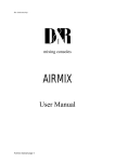
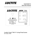
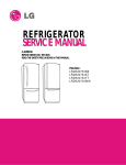
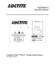
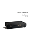
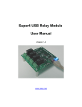
TS-480
Replacing the standard MCF (monolithic crystal filter)
The TS-480 has a monolithic crystal filter installed in the second IF (10,695 MHz).
This is a 2,4 kHz filter which is used on both RX and TX on SSB/CW/FSK and AM-Narrow.
In FM-mode the IF-filter is bypassed. The 2,4 kHz filter is named XF-932 in the service
manual and is marked with a label (10.695-0604-KDC). The filter is mounted on the
same small removable print where you can install the two optional filters and TCXO unit.
Simply remove the print and turn it upside down to unsolder the filter.
The disadvantage with the TS-480 compared to the TS-2000 is that it lack’s the
possibility to transmit with bandwidth wider than 2,4 kHz. There is a selection in the
menu where you can choose 2,0 or 2,4 kHz transmit bandwidth, but in fact this is only a
AF DSP passband cut function. The IF-filter bandwidth is still 2,4 kHz, with AF passband
frequency 500 ~ 2500 Hz (300 Hz ~ 2700 Hz in normal position).
The filter that I found is a much wider 4 kHz monolithic crystal filter named 10M4D with
housing (package) called D1. The 10M4D is a 8-pole filter with excellent characteristics.
This filter is available from sunny electronics corporation. Minimum order is 2 units, price
around $ 100 for both including shipping.
Link : http://www.sunnyna.com/en/products/pro03.htm
10M4D Filter curve plot:
Pass bandwidth (-6dB) 4 kHz
Stop bandwidth (-80 dB) 10 kHz
Ripple : 2 dB
Insertion loss : 4 dB
Guaranteed attenuation : 90 dB
Terminating impedance kΩ / pF : 1 / 10
Number of poles : 8
Note:
By installing the optional 1,8 kHz SSB-filter (YF-107SN) you can easily switch this in to
reduce strong nearby stations. This optional SSB filter is only active in RX and not TX,
your TX signal will always be routed thru the 4 kHz 10M4D filter.
The TS-480 frequency drift are noticeable (especially on 50 MHz band), so I recommend
installing the optional TCXO unit (SO-3). After installing this, the radio is dead stable after
frequency calibration.
Modification procedure :
Remove the small filter unit board
Soldering points on the units rear side. We also installed the TCXO unit (SO-3) at the same
time, but found that because of the copper surface on the board was oxidized, we could not
make the solder attach to the soldering points! Use a tiny piece of fine sand paper on the end
of a match or something to carefully remove the oxide. Clean afterwards with alcohol. Also
clean the pins of the TCXO unit with alcohol before installing it in the board. We used special
solder without lead, but with silver and copper (Sn 96,5%, Ag 3%, Cu 0,5%). This worked
very nice.
Need help to solve some issues:
After removing the original filter we immediately noticed that this filter had several SMD
components installed in the cavity underneath. My worries grow, since the replacement filter
do not have any visible components. But maybe these are hidden beneath the bottom cover,
since the bottom plate of this filter is lower than on the original Kenwood filter. Unfortunately
the service manual does not show the internal circuit in the Kenwood filter. The replacement
10M4D filter is specified with terminating impedance 1 kΩ/ 10pF, and I’m not sure if this is
the load that the filter presents or if it needs that circuit outside the filter. I must admit that in
this area I lack the skills to determine this. Maybe someone can explain this ?
After modification:
How the radio worked with this filter :
We where not sure what to expect when we turned the radio on after installing the filter.
First impression where quite good, the radio received with a very open and rich sound.
With the RX equalizer turned off we clearly had to adjust the HI side of the AF DSP filter
down to 4000 or 3400 Hz to reduce some hiss in a crowded band.
Problems:
But after a while we also noticed that the IF SHIFT rotary knob curiously have no function
any longer? Turning this knob from one side to another had no noticeable effect, I don’t know
why. Maybe the IF filter is so wide that you can’t reach the filter skirts any more?
Or maybe the IF shift is malfunctioning for some reason?
One other thing we noticed is that when you tune up or down in frequency reaching the point
where you start to hear a station, you first hear the station with a distorted sound like listening
to a station on LSB when the station transmits on USB. After turning further in frequency
about 2-3 kHz further, you hear the station clearly like it should be. This is also curious,
maybe there is some adjustment to correct this also. Maybe carrier levels or carrier points
needs to be recalibrated? (need oscilloscope to do this).
It eventually turned out that there is a problem on transmit as well, when listening to the
modified radio from a few miles away I noticed that something was wrong. The audio
sounded a bit hollow and strange, and in LSB mode I could hear that even 5-6 kHz above the
transmit frequency it was a lot of carrier signals present from the radio. This must be because
of some sort of incorrect carrier level or mismatch to the filter circuit, maybe the terminating
impedance? We will try to consult the service manual to solve this problem.
I also wish that someone with a lot of knowledge could dive in to this matter and solve it.
Note that on a very crowded band the radio has a lot more problems with interfering nearby
stations now than with the original filter. For people who operate mostly on crowded bands at
night etc. I suggest you do not install this filter !
Apart from the issues mentioned above, we found no negative effects on the radio.
Everything works fine. The transmit audio (apart from the hollow sound) is also reasonably
good, works OK with the original hand mike and also with the MC-60A desktop microphone
and mic gain at 60%. I believe the transmit audio has ESSB potential if the problems
mentioned above are solved.
But I must admit that because of the problems that occurred after this modification, I would
not recommend anyone to do this modification before the problems are solved.
By placing this document on the web, I hope that some skilled persons can help us solve
these issues and maybe make this modification work 100%. Please place the corrections
and notes under replies for this modification to help us!
June 26’Th 2006
Anonymous
Warning ! This is a difficult modification ! Be careful ! If you destroy the filter board, you
can probably buy a complete new board from Kenwood and replace it (easy, but expensive).