1
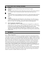
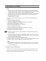
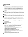
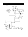
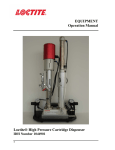
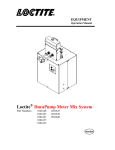
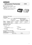
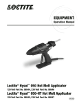
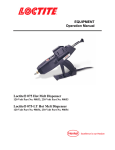
EQUIPMENT
Operation Manual
Exposure Time
TIMER
LT4H
UP
RESET
Lamp On
LOCK
N iS
Timed
DOWN
Lamp Hours
HOURS
1
10
CURTIS
UV
Manual
Warning: UV Energy is transmitted from the end of the
light guide. Protective eyewear equipped with side shields
are required that meet ANSI Z80.3 & Z87.1 Certification.
Spare Components
Description
P/N
984818 Lamp & Reflector
983677 Single Light Guide, 1M
983684 Dual Light Guide, 1M
951681 Single Light Guide, 1.5M
7740
UV Wand System
Item No. 98157A
Loctite® Zeta® 7740 UV Curing Wand System
Part Number: 98157A
TABLE OF CONTENTS
1. PLEASE OBSERVE THE FOLLOWING............................................................................................................3
1.1
1.2
1.3
1.4
EMPHASIZED SECTIONS ....................................................................................................................................3
ITEMS SUPPLIED ...............................................................................................................................................3
FOR YOUR SAFETY ..........................................................................................................................................3
FIELD OF APPLICATION, (INTENDED USAGE)....................................................................................................4
2. DESCRIPTION .......................................................................................................................................................4
2.1
2.2
THEORY OF OPERATION ...................................................................................................................................4
OPERATING ELEMENTS AND CONNECTIONS, REFERS TO FIGURE 1 ...................................................................5
3. TECHNICAL DATA...............................................................................................................................................7
3.1 ENERGY REQUIREMENTS .....................................................................................................................................7
3.2 DIMENSIONS.....................................................................................................................................................7
3.3 UV OUTPUT CHARACTERISTICS .......................................................................................................................7
4.INSTALLATION......................................................................................................................................................7
4.1 SPACE REQUIREMENTS ........................................................................................................................................7
5. OPERATING THE UNIT.......................................................................................................................................8
5.1 INSERTING AND REMOVING THE LIGHT GUIDES...................................................................................................8
5.2 POWERING UP ......................................................................................................................................................8
5.3 ADJUSTING DUAL WAND FOR MAXIMUM OUTPUT ..............................................................................................9
5.4 USING FOOT SWITCH / REMOTE DEVICE ............................................................................................................10
6. CARE AND MAINTENANCE.............................................................................................................................11
6.1
REPLACING THE LAMP MODULE ....................................................................................................................11
7. TROUBLESHOOTING ........................................................................................................................................12
8. DOCUMENTATION ............................................................................................................................................13
8.1 WIRING DIAGRAM..........................................................................................................................................13
8.2 PIN CONNECTIONS ..........................................................................................................................................14
8.3 REPLACEMENT PARTS AND ACCESSORIES ......................................................................................................14
9. WARRANTY .........................................................................................................................................................15
1.
1.1
Please Observe the Following
Emphasized Sections
WARNING!
Refers to safety regulations and required measures that protect the operator or other persons
from injury or danger to life.
Caution!
Emphasizes what must be done or avoided so that the unit or other property is not
damaged.
Notice:
Gives recommendations for better handling of the unit during operation or adjustment, as
well as for service activities.
1.2
Items Supplied
1 ZETA® 7740 UV Curing Wand System
1 Pair of UV protective glasses
1 Foot switch
1 Users manual
1 Power cord
1.3
For Your Safety
For safe and successful operation of the unit, read these instructions completely. If the
instructions are not observed, the manufacturer can assume no responsibility. Be sure to
retain this manual for future reference.
WARNING!
Always wear the included UV safety glasses or glasses that conform to ANSI Z87.1/CSA
Z94.3 when operating the unit.
WARNING!
Always cover hands, face and other parts of the body that may be exposed to UV light.
WARNING!
Never look into the end of the light guide.
WARNING!
Never open the shutter mechanism without the light guide installed.
WARNING!
Never remove the cover of the unit without first switching the power off and unplugging
the power cord.
WARNING!
Damage to the power cord or the housing can result in contact with live electrical parts.
Check the power cord and housing before each use. If the power cord or unit is damaged,
do not operate.
The unit may be repaired only by a Loctite authorized service technician.
1.
Please Observe the Following (continued)
Caution!
Never turn the unit on without the lamp connected to the power supply.
Caution!
The energy emitted from the end of the light guide can heat any surface that it is directed
at. Care must be taken to determine the proper offset distance and exposure time.
Caution!
Turning the lamp on and off frequently will cause the UV output of the lamp to decline at
a faster rate. It is recommended that the unit be left on during breaks and short down
times.
Caution!
Avoid making sharp bends in the light guide, as this will cause a loss of UV energy or
possibly cause permanent damage. To prevent permanent damage, the minimum bend
radii are 2.4 inches for a single light guide and 1.6 inches for a dual light guide.
1.4
Field of Application, (Intended Usage)
This Loctite® ZETA® 7740 UV Curing Wand System is designed for use with Loctite
products that cure when exposed to ultraviolet light produced by the unit. The UV energy
is directed towards the product through a liquid filled light guide that is ordered
separately. Several configurations of light guides are available from Loctite, including
single and dual ended types. The unit is also capable of interfacing with an external relay
or PLC circuit.
2.
Description
2.1
Theory of Operation
When the unit is switched on, electrical power is immediately supplied to the lamp and ignition should
occur within several seconds. As soon as the lamp ignites, the green, “Lamp On” indicator, located
on the panel, will come on. Also, an internal relay will change state, making a closure across pins
three and four of the footswitch connector, located on the rear panel of the unit. It will take several
minutes for the lamp to reach full power. Curing takes place when the shutter is opened, allowing UV
light to be directed from the end of the liquid filled light guide to the adhesive. The curing parameters,
(UV irradiance and exposure time) must be determined before use. The UV irradiance at the adhesive
surface can be varied by adjusting the distance of the light guide from the bond. If the light guide is
moved to within ½ inch of the adhesive surface, vapors from the curing process may build up on the end
of the light guide, reducing the UV intensity. The exposure time required to complete the curing process
depends primarily on the UV irradiance and the properties of the adhesive product.
The timed exposure cycle starts by momentarily engaging the footswitch or when an externally operated
device such as a PLC makes a relay closure across pins 1 and 9 of the nine pin footswitch connection on
the rear panel. In the manual operating mode, the shutter remains open for as long as the footswitch or
alternate external device maintains contact between pins 1 and 9.
2.
Description (continued)
The hour meter, located on the front panel, records the total hours of operation accumulated by the lamp.
UV lamps undergo a gradual reduction in UV output over time and it is recommended that the lamp
output be monitored on a regular basis. Turning the lamp on and off frequently will speed up the
degradation process, therefore, it is recommended that the unit be left on during short work
breaks such as lunch and other idle periods.
Notice: The hour meter should only be reset when a new lamp is installed.
2.2
Operating Elements and Connections, refers to Figure 1
1. Power Inlet Module
Connect the line cord to power inlet module.
2. Power Fuse Holder
Fuse is located in the power module.
3. Power Switch
4. Foot Switch Connection
Standard 9 pin “D” connector for foot switch or other external switch.
5. Light Guide Receptacle
Is used to retain the light guide.
6. Digital Exposure Timer
Controls the period of time the shutter is opened. The UV time is set by pressing the
buttons located directly under the LCD, which indicates seconds. The manual/timed
selector switch must be set to "timed.” When the foot switch is engaged the shutter
mechanism will open for the indicated time and the timer will begin counting down.
When the unit times out the shutter will close and the LCD will indicate the original
pre-set time interval.
7. Lamp Hour Meter
The hour meter indicates the cumulative time that the lamp has been ON.
8. Mode Selector – Manual/Timed
When set to “manual” the UV light is passed through the light guide for as long as the
foot switch is pressed. In the “timed” mode, the timer’s LCD display indicates
exposure time and the cycle is initiated when the foot switch is momentarily engaged.
9. Lamp On Indicator
The lamp will ignite when the main power is switched on. The green lamp on
indicator located on the front panel will light to confirm that the lamp is operating.
An internal relay connected to pins three and four of the footswitch connector will
also close to indicate that the lamp is on.
2. Description (continued)
Exposure Time
TIMER
LT4H
6
UP
RESET
Light
Guide
5
Receptacle
Lamp On
LOCK
N iS
Timed
DOWN
Lamp Hours
HOURS
1
10
7
CURTIS
UV
Manual
Warning: UV Energy is transmitted from the end of the
light guide. Protective eyewear equipped with side shields
are required that meet ANSI Z80.3 & Z87.1 Certification.
7740
Spare Components
Description
P/N
984818 Lamp & Reflector
983677 Single Light Guide, 1M
983684 Dual Light Guide, 1M
951681 Single Light Guide, 1.5M
UV Wand System
Item No. 98157A
8
Foot
Switch
4
Connection
9-Pin D-Sub
KNOCKOUT
Rocky Hill, Connecticut 06067, U.S.A.
Input: 90-265 VAC, 50/60 Hz.
2.4 A @ 115 VAC & 1.2 A @ 240 VAC
Fuse: 4 Amp, 250 V
Lamp: 100 Watt
Made in U.S.A.
Power
Switch
3
Fuse
Holder
2
Power
Inlet
Module
1
Warning
Disconnect and Refer to
Manual Before Servicing Unit.
FOR SPARE PARTS, MANUALS, REPAIRS,
OR TECHNICAL ASSISTANCE:
Visit us at equipment.loctite.com
or call Henkel Corp. at:
USA - (1) 860-571-5174
Germany - (49) 89-9268-0
Singapore - (65) 6482-3881
Figure 1.
Label P/N: 988341
Hour Meter Reset
3. Technical Data
3.1 Energy Requirements
Power Supply: 90-132 VAC or 180-265 VAC, 50/60 Hz.
Power Protection: 4A/250V fuse
Auxiliary Control Voltage: 24 volts DC
Main fuse located in power module in rear of unit: 4A, 250V
3.2 Dimensions
Width
11.0 inches
Depth:
12.5 inches
Height:
7.6 inches
Weight: 18 pounds
Light Guides (supplied separately)
Single end light guide, part 983677 – 1000mm long x 5mm diameter
Single end light guide, part 951681 – 1500mm long x 5mm diameter
Dual end light guide, part 983684 – 1000mm long x 3mm diameter
3.3 UV Output Characteristics
Typical output:
9 - 11 W/sq.cm (using 5mm x 1000mm lightguide)*
UV Spectral Range:
200 – 400 nM
Primary Peak:
365 nM
Secondary Peaks:
315, 335 nM
*Exact output measurement is dependent on the brand and calibration method of the meter used,
as well as the condition and straightness of the light guide.
4. Installation
4.1 Space Requirements
A space of 12" wide x 16" deep x 8" height is required. It is important to have at least 8
®
®
inches of space behind the unit to insure proper airflow. The Loctite ZETA 7740 UV
Curing Wand System only needs to be connected to a 120V/60Hz outlet to operate.
Caution!
Do not block the intake and exhaust fans located on the back of the housing.
Caution!
The unit should always be operated with the rubber support feet resting on a flat surface.
Caution!
Do not operate with the unit resting on its side or at an angle greater than 15 degrees,
front to back.
5. Operating the Unit
5.1 Inserting and Removing the Light Guides
Caution!
Be sure to remove the plastic end caps before attempting to use the light guide.
Caution!
If the free end of the light guide is secured at a fixed location, sharp bends should be
avoided as it will cause a decrease in UV power.
Caution!
Never pull on the jacketing portion of the light guide. During installation or removal,
grasp the light guide on the strain relief nearest the input end of the light guide.
•
Installing single light guide - Insert the large end of single light guide into the
light guide receptacle located on the left side of the front panel. Push light guide
firmly until it is fully engaged.
• Installing dual light guide – Insert the dual wand light guide into the light
receptacle and rotate the collar assembly so that the scribed line on the collar is in
the 12 o’clock position. See section 5.3 “Adjusting Wand for Maximum Output.”
Notice:
It is important that the rotational position of a dual light guide be set to maximize the
UV output for each wand. This setting is specific to each curing unit and light guide
(See section 5.3 - Adjusting Dual Wand).
5.2 Powering Up
1. Switch the main power ON. The power switch is on the lower left of the rear panel.
2. The green LED on the front panel will come on to confirm that the lamp has ignited
and an internal relay will make a closure across pins three and four of the
footswitch connector.
3. Allow approximately five minutes for the lamp to reach full power.
4. Set the operating mode selector switch to “timed” or “manual”. For manual
operation, engage the footswitch to start UV exposure and hold until the curing
cycle is complete. When the footswitch is released the exposure will end
immediately. For timed operation use the keys directly below the numbers on the
display to set the desired exposure time. Momentarily engage the footswitch to start
the cycle. The UV exposure will begin immediately and continue until the system
times out.
5. UV exposure cycles may be initiated by using an externally operated device, such
as a PLC controlled relay in place of the footswitch.
Notice:
Avoid shutting the main power off for brief periods of time. Frequent start-ups will
cause the lamp to decay at an accelerated rate. If the system is shut down, wait a
minimum of ten minutes before restarting. Once the lamp is ignited, allow it to operate
for a minimum of fifteen minutes before turning it off.
5. Operating the Unit (continued)
5.3 Adjusting Dual Wand for Maximum Output
This Set Screw Locks
The Balancing Adapter
To The Units Base
Adapter Hub
Scribe Line
Exposure Time
TIMER
This Set Screw Locks
The Light Guide In
Position After Balancing
The Output Power
LT4H
UP
RESET
Lamp On
LOCK
N iS
Timed
DOWN
Lamp Hours
HOURS
1
10
CURTIS
UV
Manual
Warning: UV Energy is transmitted from the end of the
light guide. Protective eyewear equipped with side shields
are required that meet ANSI Z80.3 & Z87.1 Certification.
Spare Components
P/N
Description
984818 Lamp & Reflector
983677 Single Light Guide, 1M
983684 Dual Light Guide, 1M
951681 Single Light Guide, 1.5M
7740
UV Wand System
Item No. 98157A
Objective
®
Balance the UV output from the two light guides of Loctite P/N 984589.
Tools Needed
3/32 inch hex key
®
Loctite 98720 UV Spot Radiometer P/N: 1079258
5. Operating the Unit (continued)
Setup
1. Install the collar assembly over the part of the light guide receptacle that protrudes
from the front of the unit. Rotate the collar assembly until the scribed line is in the 12
o’clock position. Use the set screw to secure the collar in that position.
2. Insert the input end of the light guide into the light guide receptacle/collar assembly
pushing it as far forward as it will go. Tighten the set screw on to the light guide.
3. Turn on electric power to unit.
4. Set shutter timer to 2 seconds.
®
5. Insert one of the light guide ends into a Loctite 98720 UV Spot Radiometer P/N:
1079258.
6. Press the radiometer start switch.
7. Actuate foot switch to open shutter.
8. Release the radiometer start switch while the shutter is still opened.
9. Read and record the radiometer reading.
10. Position the second light guide in the radiometer.
11. Press the radiometer start switch.
12. Actuate foot switch to open shutter.
13. Release the radiometer start switch while the shutter is still opened.
14. Read and record the radiometer reading.
15. Compare the two radiometer readings.
16. If the lower reading is equal to or greater than 90% of the higher reading, the dual
wand is balanced.
17. If the lower reading is less than 90% of the higher reading, loosen the set screw and
rotate the collar a small increment around the light guide receptacle. Use the set screw
to secure the collar in that position.
18. Take and compare another set of radiometer readings.
19. Continue until the lower reading is equal to or greater than 90% of the higher reading.
20. Tighten set screw to lock the input end of the dual wand in position.
Notice:
If a radiometer is not available, it is recommended that Loctite Service be contacted at
1-800-LOCTITE (1-800-562-8483) to insure optimum performance when installing a
new dual ended light guide.
5.4 Using Foot Switch / Remote Device
®
The ZETA 7740 can also be actuated using a foot switch or by external devices. The
foot switch connection is made up of a 9 pin D connector. Making a dry-contact relay
closure across pins 1 and 9 can actuate the unit.
6. Care and Maintenance
Notice:
It is recommended that the UV output from the lamp be monitored regularly using a
®
Loctite 98720 UV Spot Radiometer P/N: 1079258. If a radiometer is not used to
monitor the lamp, it is recommended that the lamp be replaced when the hour meter,
located on the front panel, indicates 1,000 hours of operating time has elapsed. It is
normal for the lamp output to slowly decline over operating time, however, the
effective life of the lamp will decrease significantly faster if it is turned on and off
frequently.
Caution!
It is recommended that the end of the light guide be positioned no closer than ½ inch
from the Loctite® product being cured. The heat transmitted by the lamp can adversely
affect the properties of the cured product or possibly cause damaged to the part surface.
Notice:
Vapors from some products may gradually accumulate on the end of the light guide,
reducing the UV output. It should be inspected regularly and cleaned as necessary using
isopropyl alcohol and a soft, clean cloth.
Caution!
Avoid placing sharp bends in the light guide. This reduces the UV output and may
permanently damage the light guide. If the light guide is mounted on a fixture, secure it
by the metal exit fitting and not the flexible plastic section.
Notice: The intake and exhaust fan filter elements should be replaced as needed to
insure proper cooling of the power supply and UV lamp assembly. They should be
inspected routinely.
6.1
Replacing the Lamp Module
Caution!
Do not touch the lamp module reflector or the lamp. Contaminants from hands will
create “hot spots” and cause the module to fail prematurely. If either are accidentally
touched, carefully wipe them with a clean, soft cloth and isopropyl alcohol.
1. Switch the power off and unplug the unit.
2. Allow several minutes for the lamp to cool.
3. Remove the four screws from the sides of the housing and lift off the cover.
4. Disconnect the lamp leads by separating the Male/Female connector.
5. Pull back on the spring loaded lamp retaining bar.
6. Remove the lamp/reflector assembly from the mounting block.
7. Install the new lamp module.
8. Release the lamp retaining bar. Be sure the lamp is flush in the mounting hole.
9. Reconnect the power leads.
10. Replace the lid.
11. Press the lamp hour reset switch to set the hour meter to zero.
Notice: Step 11 should only be done when a new lamp is installed.
6.1
Replacing the Lamp Module (continued)
WARNING!
The UV lamp used in this unit contains a very small amount of mercury. Disposal of
lamps should be done in accordance with state and local regulations.
7. Troubleshooting
Type of Malfunction
Possible Cause
Correction
Power does not come on
– No voltage present.
– Defective Fuse.
– Defective Power Supply.
– Defective Switch.
• Check wall circuit.
• Replace fuse.
• Call 800-562-8483.
• Call 800-562-8483.
The shutter mechanism can be
heard opening and closing, but no
light is emitted from the light guide.
– Lamp failure.
– Defective power supply.
– Defective shutter.
• Replace lamp module.
• Call 800-562-8483.
• Call 800-562-8483.
Power comes on but light is not
emitted from the light guide. The
shutter mechanism makes no
noise when foot switch is engaged.
– Foot switch is not plugged in properly.
– Defective foot switch.
– Defective shutter mechanism.
• Check foot switch connection.
• Call 800-562-8483.
• Call 800-562-8483.
All system functions appear to be
operating, but the product does
not cure completely, or if a radiometer
is used to monitor the UV output, the
power is low.
– UV output has declined due to normal
lamp aging.
– End of light guide has an accumulation of
product or other contaminants
– Light guide is not fully inserted in
receptacle.
– Light guide has exceeded is useful life.
• Replace lamp module.
• Clean light guide with soft cloth
and isopropyl alcohol.
• Check light guide connection.
• Replace light guide.
8. Documentation
8.1
Wiring Diagram
BACK-UP SOURCE
OMRON RELAY TIMER
988825
PRIMARY SOURCE
NAIS RELAY TIMER
988802
4
OMRON HOUR
METER
H7ET-NV-BH
1 (+)
2 (-)
3
1 (+)
(-) 2
4
4
3
+
6 7 8 9 10
5
TO RELAY
OUTPUT PIN ON
TIMER
6
3
CURTIS HOUR
METER
701DR001O
INITIATE
RELAY
OUTPUT
INITIATE
TO TIMER
INITIATE PIN
7
2
1 2 3 4 5
8
1
RELAY OUTPUT
FROM TIMER
-
-
+
-
INPUT TO HOUR
METER
12VDC
INPUT
+
-+
RELAY
OUTPUT
TIMED
EXTERNAL
FOOTSWITCH
SHUTTER
SOLENOID
TIMER
INPUT
PIN 9
MANUAL
MODE
SELECTOR
SWITCH
PIN 1
CHASSIS
GROUND
ENCLOSURE
FAN
+
-
ENCLOSURE
FAN
+
-
CATHODE
HV
+12V
ANODE
RTN
-
LAMP OUTPUT
+9V
+
12VDC AUX.
OUTPUT
SAFEARC
BALLAST
MC7809ACT
CML
5102H5-5V
MOUNTED ON
FRONT PANEL
G
300/5%/1/4W
HONEYWELL
SDP-8405-003
N
L
OMRON
G5SB-14-DC9
1N4002
CHASSIS
GROUND
PARTITION
LOCK-OUT
SWITCH - N/O
PIN 3
IRF-510
N/C
L
PIN 4
10K/5%/1/4W
N
REAR PANEL FOOTSWITCH
CONNECTOR
L
N
G
FILTER
6.3 AMP
L
N
G
GND TO
CHASSIS/LID
POWER INPUT
MODULE
8.2 Pin Connections
8.3
Replacement Parts and Accessories
Loctite Part Number
Description
984818
Replacement Lamp Module
983677
Single End Light Guide (5 mm x 1M)
983684
Dual Ended Light Guide (3 mm x 1M)
951681
Single Light Guide (5 mm x 1.5M)
984770
Fan Filter Element, Quantity 5
97210
UV Safety Glasses
986051
Foot Switch Assembly
1079258
Loctite 98720 UV Spot Radiometer
951639
Dual Wand Adapter Kit
856083
Power Supply / Ballast
®
9. Warranty
Henkel expressly warrants that all products referred to in this Instruction Manual for the UV Curing Wand
System, (hereafter called “Product”), shall be free from defects in materials and workmanship. Liability for
Henkel shall be limited, as its option, to replacing those Products which are shown to be defective in either
materials or workmanship or to credit the purchaser the amount of the purchase price thereof (plus freight
and insurance charges paid therefor by the user). The purchaser’s sole and exclusive remedy for breach of
warranty shall be such replacement or credit.
A claim of defect in materials or workmanship in any Product shall be allowed only when it is submitted in
writing within one month after discovery of the defect or after the time the defect should reasonably have
been discovered and in any event, within 2 years after the delivery of the Products to the purchaser. This
warranty does not apply to perishable items, such as fuses and fan filters. The lamp is fully warranted for
500 hours of operation for failure to ignite. The lamp is also warranted to produce 50% of the minimum
rated intial output at 500 hours of operating time, when measured using an in-calibration Loctite 98720 UV
Spot Radiometer, and a new Loctite 5mm x 1000mm lightguide in a fully straight orientation. No such
claim shall be allowed in respect of products which have been neglected or improperly stored, transported,
handled, installed, connected, operated, used or maintained. In the event of unauthorized modification of
the Products including, where products, parts or attachments for use in connection with the Products are
available from Henkel, the use of products, parts or attachments which are not manufactured by Henkel, no
claim shall be allowed.
No Products shall be returned to Henkel for any reason without prior written approval from Henkel.
Products shall be returned freight prepaid, in accordance with instructions from Henkel.
NO WARRANTY IS EXTENDED TO ANY EQUIPMENT WHICH HAS BEEN ALTERED, MISUSED,
NEGLECTED, OR DAMAGED BY ACCIDENT, OR IF THE SYSTEM USED TO DISPENSE ANY
LIQUID MATERIAL OTHER THAN HENKEL PRODUCTS.
EXCEPT FOR THE EXPRESS WARRANTY CONTAINED IN THIS SECTION, HENKEL MAKES NO
WARRANTY OF ANY KIND WHATSOEVER, EXPRESS OR IMPLIED, WITH RESPECT TO THE
PRODUCTS.
ALL WARRANTIES OF MERCHANTABILITY, FITNESS FOR A PARTICULAR PURPOSE, AND
OTHER WARRANTIES OF WHATEVER KIND (INCLUDING AGAINST PATENT OR
TRADEMARK INFRINGEMENT) ARE HEREBY DISCLAIMED BY HENKEL AND WAIVED BY
THE PURCHASER.
THIS SECTION SETS FORTH EXCLUSIVELY ALL OF LIABILITY FOR HENKEL TO THE
PURCHASER IN CONTRACT, IN TORT OR OTHERWISE IN THE EVENT OF DEFECTIVE
PRODUCTS.
WITHOUT LIMITATION OF THE FOREGOING, TO THE FULLEST EXTENT POSSIBLE UNDER
APPLICABLE LAWS, HENKEL EXPRESSLY DISCLAIMS ANY LIABILITY WHATSOEVER FOR
ANY DAMAGES INCURRED DIRECTLY OR INDIRECTLY IN CONNECTION WITH THE SALE
OR USE OF, OR OTHERWISE IN CONNECTION WITH, THE PRODUCTS, INCLUDING, WITHOUT
LIMITATION, LOSS OF PROFITS AND SPECIAL, INDIRECT OR CONSEQUENTIAL DAMAGES,
WHETHER CAUSED BY NEGLIGENCE FROM HENKEL OR OTHERWISE.
Henkel Corporation
One Henkel Way
Rocky Hill, CT 06067-3910
Henkel Canada Corporation
2225 Meadowpine Boulevard
Mississauga, Ontario L5N 7P2
Henkel Corporation
Automotive / Metals HQ
32100 Stephenson Hwy.
Madison Heights, MI 48071
Henkel Ltda.
Rua Karl Huller, 136 – Jd.
Canhema 09941-410
Diadema/SP, Brazil
Henkel Capital, S.A. de C.V.
Calzada de la Viga s/n Fracc. Los Laureles
Loc. Tulpetlac, C.P. 55090
Ecatepac de Morelos, Edo. de México
www.loctite.com
Loctite is a trademark of Henkel Corporation, U.S.A. © Copyright 2006. Henkel Corporation
All rights reserved. Data in this operation manual is subject to change without notice.
Manual P/N: 988781, Rev L, Date: 08/2009