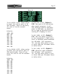
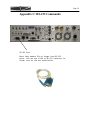
1
Price: $20.00
DZ CompanY • LOVELAND, COLORADO
Page
DZKit
USER’S MANUAL
SIENNA
HF RECEIVER/Transceiver
Page 2
DZ COMPANY CONTACT INFO
Orders, parts, phone assistance.....................................................................(970) 667-2254
Email orders............................................................................................... [email protected]
Email technical support ......................................................................... [email protected]
Web site ....................................................................................................... www.dzkit.com
Mail:
DZKit
4321 W. Eisenhower Blvd.
Loveland, CO 80537
YOUR DZKIT 90-DAY FULL WARRANTY
During your first ninety (90) days of ownership, DZ Company will replace or repair free of charge—as soon as
practical—any parts which are defective, either in materials or workmanship. You can obtain parts directly from
DZ Company by writing us, emailing us or telephoning us. And we’ll pay shipping charges to get those parts to
you—anywhere in the world.
We warrant that during the first ninety (90) days of ownership, our products, when correctly assembled,
calibrated, adjusted and used in accordance with our printed instructions, will meet published specifications.
You will receive free consultation (except for the cost of your long distance phone call) on any problem you may
encounter in the assembly or use of your DZKit product. Just drop us a line, email us, give us a call, or visit our
website and click on “Support”. That will give you access to free on-line support and a discussion group. Sorry,
we cannot accept collect calls.
Our warranty, both expressed and implied, does not cover damage caused by the use of corrosive solder,
defective tools, incorrect assembly, misuse, fire, customer-made modifications, floods or acts of God, nor does it
include reimbursement for customer assembly or setup time. The warranty covers only DZKit products and is
not extended to non-DZ allied equipment or components used in conjunction with our products or uses of our
products for purposes other than as advertised.
If you are ever dissatisfied with our service—warranty or otherwise– or our products, please write or email the
president, Brian Wood, W0DZ, and he will make certain your problems receive prompt, personal attention.
THE DZ COMPANY, LLC
LOVELAND, CO 80537
Page 3
TABLE OF CONTENTS
Operation
Introduction ...................................... 4
Back Panel........................................ 6
Front Panel ....................................... 8
Basic Operation .............................. 14
The Receiver .................................. 18
The Transmitter .............................. 28
The Antenna Tuner ......................... 36
External Amplifiers ........................ 38
The Menu ....................................... 40
Appendix A: APP Connectors ........ 50
Appendix B: External Keypad........ 52
Appendix C: RS-232C Commands. 54
Appendix D: Balanced Mic usage .. 81
Of the
Sienna HF Receiver/Transceiver
DZ COMPANY
LOVELAND, COLORADO
Copyright © 2010
The DZ Company, LLC
All rights reserved
3/7/11
Sienna
Page 4
Introduction
addition, there are no dead spots Your new Sienna HF Receiver/
Transceiver represents the perfect in the shortwave bands, which is a necessary side effect of down‐
integration of computers and ra‐
conversion radios. dio. It’s not just a radio, and not just a PC. In fact, if you don’t like PCs, you don’t have to At 70MHz, it is not currently pos‐
have one! sible to have narrow crystal fil‐
ters) ‐ they are just too expen‐
Some “software‐defined ra‐
sive. But Inrad manufactures an dios” (SDR) require you to have a excellent 6‐pole crystal filter PC, either internal or external, for the Yaesu FT‐1000MP that Si‐
because after converting the radio enna also uses. At 4.5kHz, it is spectrum into digital samples, still adequate for good AM copy, that data is passed over a high while providing much better block‐
speed link to a PC for processing. ing dynamic range than you would Sienna’s PC is totally optional, get with a wide filter. because we know that some of you like PCs and some do not. Sienna is also one of the only ra‐
dios on the market with a com‐
Sienna uses a triple conversion pletely separate transmitter. receiver. By “up‐converting” the There are no shared components or entire 30MHz spectrum to 70MHz, it oscillators. Thus, full‐duplex op‐
becomes possible to easily filter eration, such as that used in sat‐
out the mixing products, resulting ellite operation, is possible. in excellent image rejection. In Page 5
Modularity is another of Sienna’s common controls are on the front features. The chassis has six com‐ panel, while the ones used less partments — power, receiver, often are in the first level menu transmitter, 100W amp, control and (which is always on the display—
PC. This affords excellent shield‐ AGC, NB, VOX/PTT, Antenna selec‐
ing and also provides easily ser‐ tions). Other less often used viceable components. Should the functions are in a very simple transmitter ever need service, it menu system. An external 12‐button can be removed without disturbing keypad is supported, which allows anything else. easy access to memories, CW buff‐
ers and one‐button‐per‐band Cooling in the Sienna is also im‐ bandswitching. portant. Two central fans pull air in from the front sides, cooling The internal “embedded” PC adds the display and controller chips, all the features of a PC (logging, passing it across the transmitter, web connectivity, USB, rig con‐
amplifier and DC power distribu‐
trol, digital modes, mic process‐
tion boards, and exhausting it out ing, etc.) that are often handled the back. Thermistors regulate the in other rigs by the use of expen‐
fan speeds. sive “rig interface” boxes. With Sienna’s internal PC, you don’t Finally, a lot of attention has have nearly the mess of external been paid to ergonomics. Sienna’s wires that you would have with an controls are grouped by function, external PC, making portable op‐
and dual functionality is used erations much more convenient. sparingly and carefully. The most Page 6
Back Panel
1 2 3 4 5 6 7 8 9 10 11 12 13 14 15 16 17 18 19 1. Keypad. Connect a 12‐button keypad such as the Yaesu FH‐1 to this connector. See Appendix J for details on how to build your own. This allows you to change bands with a single keypress, use the memory features, and select a band directly instead of using band up or down controls. 2. Key. The manual and paddle jacks are connected in parallel with those on the front panel and are both active simultaneously so that you do not have to turn the keyer off to use a straight key or ex‐
ternal keying device. 3. Audio. Line‐in and Line‐out are stereo 600 ohm audio inputs and outputs that can be connected to the sound card on a PC or other audio devices. Line level is nominally 200mVrms. 4. 455KHz IF Out. This is a large bandwidth output centered at 455KHz that can be connected to a spectrum analyzer or panadapter to view signals on the current receive band. 5. RX Antenna. This BNC connector allows you to run the receiver from an antenna that is not connected to the transmitter. It is pro‐
tected from static by a gas discharge tube and by back‐to‐back 2.7V zener diodes, but not against high transmitter power. Maximum input power is 1mW (0dBm). 6. ALC In (RED). This phono connector allows 0 to –5VDC input from ex‐
ternal linear amplifier to control the output level of the internal 100W amp. Higher negative voltages produce lower output power. 7. XVT Out (GREEN). This phono connector is the output of the trans‐
mitter prior to amplification. Output level is 1mW (0dBm) max. It is suitable for driving a transverter. 8. Mic In (BLUE). Unbalanced audio from this phono connector is mixed with the front panel microphone connector or with the internal line signal from the PC and/or receiver. The input impedance is about Page 7
600 ohms. Note that if you have a MIO card installed (see item 13), this is NOT the same microphone input as that red connector. This mic input connects directly to the transmitter board and can be routed to the PC internally only if you do NOT have a MIO card. If you use the mic input on the MIO card, its audio will pass through the PC’s sound card, allowing you to do equalization, compression, mixing with CTCSS and DTMF tones, and other things in software be‐
fore routing the output to the MIO’s SPKRS output. That audio can then be fed into the back panel MIC phono connector. 9. Antenna A. This SO‐239 connector is the main transmit/receive an‐
tenna. It is protected from static discharge by a gas discharge tube. 10.Antenna B. This SO‐239 connector is a secondary antenna. A menu item lets you select antenna A or B. It is protected from static discharge by a gas discharge tube. 11.GND. This is chassis ground. Connect this to a good earth ground. 12.DC In. These Anderson Powerpole connectors are the main DC Input. Connect these to a clean source of DC voltage from 10‐15VDC. The transmitter will operate from 12‐15V. The receiver and PC can oper‐
ate over the full range. 13.MIO. If a MIO‐6254 card is installed with the PC, its connectors appear here. This card provides high power (6W) stereo audio at the green speaker connector, and a secondary video interface (DVI), al‐
lowing you to use two monitors. It also provides an S‐video and composite video output for TV monitors. 14.PC connectors. The RS‐232C, LAN, PS/2, VGA and USB connectors are standard PC connectors. A PC reset button is located beneath the LAN connector. 15.CF Card. This tray holds the Compact Flash card that contains the Operating System and any installed software. 16.Exhaust holes. These holes serve as exhaust for the internal fan. Do not block these holes. 17.Linear. 8‐pin mini‐DIN connects to linear amplifier 18.Exhaust plate. This bracket provides exhaust for the fan that cools the DC power distribution board and optional 100W amplifier. Do not block the exhaust holes. 19.Fuse. This 25A fuse is inline between the main power input and the optional 100W amplifier. If the amplifier is not installed, this opening can be replaced with a hole cover, or used to bring cables in and out if you wish to use the compartment to hold a battery or other device. Page 8
Front Panel Controls
4 5 6 1 2 7 10 11 3 12 13 8 9 1. RF Gain (RFG or Radio Frequency Gain). This control overrides the automatic gain control (AGC) of the Receiver’s Intermediate Fre‐
quency (IF) amplifiers. In its CW (clockwise) position, the AGC has full control over the gain. As you rotate the control counter clockwise (CCW), it reduces the available gain. This control is usually left in the CW position unless extremely strong signals are present. It can also be used to reduce sensitivity so that only stronger signals are heard, which can help during contests. 2. Preamp. This switch activates the first of two available RF ampli‐
fiers. On lower frequencies, below 10MHz, this amplifier is often not needed. Above 10MHz, it is not needed when band conditions are excellent. It is useful for pulling out very weak signals on a fad‐
ing band. 3. Pre2/Atten. This switch activates the second of two available RF amplifiers only if the Preamp switch (see previous item) is pushed. If Preamp1 is off, this button serves as a 10dB attenuator. If you use the attenuator and then push the Preamp button, the attenuator is disengaged and both preamps are turned on. You should only need both preamps to pull out very weak signals, as this much RF gain increases distortion on strong signals. 4. Headphone volume. This control adjusts the gain of the headphone audio amplifier. It can be adjusted separately from speaker volume. 5. Headphone jack. Plug low impedance stereo headphones into this 3.5mm minijack connector. 6. AF Gain (AFG or Audio Frequency Gain). This control adjusts the gain of the speaker audio amplifier. Speaker volume can be adjusted separately from the headphone volume. 7. Mute. This button mutes the internal receiver. Note that if you have another source feeding into the radio, such as the internal PC’s line out or the Line In from the back panel, that source will Page 9
still be routed to the appropriate speakers. Use that source’s gain control to adjust the volume or to mute it. If you are using the Audio DSP to route the internal receiver to the PC for processing, you will want to mute the receiver so that you do not feed both un‐
processed and processed audio to the speakers at the same time. 8. Dual. This button activates dual receive. In this mode, input from the stereo Line In jack on the back panel is fed to the speakers, and the internal receiver is fed only to the right speaker. This allows you to listen to one receiver in each ear. In order to feed a mono source such as a receiver to the left channel only, you must connect the left channel to the external receiver but not the right. This can be done by using a mono minijack plug in the stereo minijack. 9. FM Squelch/NB Thresh. In FM mode, this control sets the level at which FM signals are quieted (squelched). In other modes, this con‐
trol sets the noise blanker threshold if the noise blanker is turned on. 10.Adjust. This control consists of a rotary pulse generator (RPG) and a pushbutton switch. The function of the RPG and the switch depend on the 8‐position switch immediately below it (11). 11.Multipurpose switch. This switch selects up to 8 different modes for the RPG control that is above it (10). In the CCW position, it enables the RPG to change which IF filter is selected. Pushing the RPG knob switches back and forth between the 9MHz and 455KHz fil‐
ters, and a * is placed next to the currently selected set in the display. The width of the trapezoids in the display changes to give a visual indication of the bandwidth of the selected filter. Note: when you change bands or modes, the previously saved filter is automatically selected. In positions 2‐4, the switch allows the 9MHz or 455KHz passband (whichever is selected) to be shifted right or left. Position 2 shifts left 50Hz per detent, position 3 100Hz and position 4 500Hz. Position 5 allows the pushbutton to start or stop scanning functions. Position 6 of the switch accesses the CW buffers (which are set in menu options). The rotary control selects one of the ten buffers, and the pushbutton starts the buffer. Posi‐
tion 7 is for memory buffers. Rotating the RPG selects a memory, and the pushbutton then moves it into VFO A. Position 8 is reserved for future use. 12.Microphone jack. This connector is wired for a Yaesu compatible mi‐
crophone. An external adapter is required for use with other micro‐
phones. 13.Mic Gain. This control adjusts the microphone gain. Use it with the ALC meter indication on transmit to keep from overmodulating the final amplifier. Page 10
25 28 29 18 19 20 21 22 14 15 16 17 26 32 27 30 31 23 24 14.Proc/CW Spot. In SSB mode, this button activates the RF speech processor. In CW mode, this button disables the transmitter and al‐
lows the keyer (internal or external) to be used as a SPOT control. To use this function, press the key and turn the Pitch control (20) until the sidetone frequency matches that of the received signal. This assures that you are transmitting on the same frequency as the station you wish to communicate with. CW SPOT mode can also be used for code practice, since no signal will emanate from the transmit‐
ter. It is useful to press the Mute button in this mode too, to eliminate receiver noise. You do not need to change the RF Power control when using CW SPOT. 15.Proc Level. This control adjusts the compression level. Use on SSB with the Compression scale on the meter to keep speech compression less than 10 dB. 16.Tuner. This button activates the optional internal Antenna Tuner. The tuner memory saves five settings per band. If a band segment has never been tuned, then if this switch is on, the first time you transmit on that band segment, a tuning operation will occur and the settings will be memorized. A menu option allows you to reset the tuner settings. 17.RF Power. This control adjust the transmitter power level from 0 to 12.7W or 0 to 127W, based on a menu setting. Note that this is “requested” power. Actual power is measured in real‐time by the ALC firmware and will be as close as possible to this value. 18.Sidetone Volume. In CW mode, this control adjusts the volume of the CW sidetone. Sidetone volume is also affected by the main speaker and headphone volume controls. 19.Dot Weight. This screwdriver‐adjustable pot sets the ratio of dots to spaces for the internal keyer. 20.Pitch. In CW mode, this control sets both the CW pitch (tone) and the receiver passband. Use with the CW SPOT button (14) to zero beat the transmitter to that of a received signal. 21.Dash Weight. This screwdriver‐adjustable pot sets the ratio of Page 11
dashes to spaces for the internal keyer. 22.Speed. In CW mode, this control adjusts the speed of the internal keyer from 1‐65WPM. 23.Full Break‐In. In CW mode, this button activates full break‐in. This means that the drop‐out time after you release the key is changed from that used for Semi‐Break‐in to a much faster value, allowing you to hear between the dots as you send. This is often used to avoid stepping on another operator’s toes by transmitting at the same time. However, some operators find it unsettling to listen to the receiver while transmitting. The value of drop‐out time is settable in a menu item for both Semi and Full break‐in modes. Default is 1 second for Semi break‐in and 10ms for Full break‐in. 24.Key jacks. These jacks are both active at the same time. You can plug a straight key or external keying device into the manual key input and paddles into the other. Thus, there is no need to turn the keyer off when switching to another keying device such as a PC. 25.Menu. This button activates the menu. See the detailed description of menu selections starting on page 16. 26.Page/Mode. If the menu button is NOT lit, this button allows the small tuning knob to cycle through all available modes (CWUSB, CWLSB, USB, etc.). If the menu button IS lit, this button allows the small tuning knob to cycle through all the available pages in the menu. When menu is first selected, the button comes on by de‐
fault to allow you to quickly find the desired page. Once you find it, rotating the large tuning knob turns it off. To go to another page, press the Page/Mode button again. 27.Fast/Lock. This button changes the rate at which the tuning knobs change the frequency. If enabled in a menu item, it also causes the dials to lock after a period of inactivity. 28.Clear. This button clears a RIT (Receiver Incremental Tuning) or XIT (Transmit Incremental Tuning) offset. If XIT and RIT are both off, this button enables SPLIT mode, which allows you to set the transmitter frequency and mode independently of the receiver. The display shows the current setting of VFO B, which is used only for the transmitter. In SPLIT mode, pressing the A>B (XIT) button cop‐
ies the displayed frequency (VFO A) into VFO B. Pressing A<>B (RIT) swaps the VFO frequencies and modes. 29.XIT. Transmit Incremental Tuning. With RIT and SPLIT off, this al‐
lows the small tuning knob to be used to adjust the transmitter frequency up to 16MHz from the receive frequency. The mode (USB, LSB, etc.) is not changed. See (27) for an alternative mode for this button. If the BAND button is pushed, this button changes bands to the next higher band. 30.RIT. Receiver Incremental Tuning. With RIT and SPLIT off, this al‐
Page 12
lows the small tuning knob to be used to adjust the receiver fre‐
quency up to 16MHz from its original frequency. The mode (USB, LSB, etc.) is not changed. See (27) for an alternative mode for this button. If the BAND button is pushed, this button changes bands to the next lower band. 31.BAND. Allows the XIT and RIT buttons to be used as band up/down functions. In this mode, the large tuning knob can also be used to change bands. There are five VFO A frequencies per band; when you change bands, the last used VFO A frequency is used. If you have connected an external keypad such as the Yaesu FH‐1 to the Keypad input on the back panel, you can also change bands directly without pushing the BAND button. There are 10 bands (160‐80‐60‐40‐30‐20‐17‐
15‐12‐10) and five VFOs each per band. The value of each is shown as bbb‐vv, such as 160‐1. 32.Large and small tuning knobs. These knobs are used to change fre‐
quency when not in MENU or BAND modes. When RIT and XIT and SPLIT are not on, the large knob is used for fine tuning and the small knob for coarse tuning. The FAST button changes the rate of both knobs. In MENU mode, the large knob selects a menu item on the cur‐
rent page and the small knob changes its value. In BAND mode, the large knob changes bands and the small knob selects VFO A memory 1‐
5 (and you will see the number change that is located right above the “kHz” in the display). When RIT or XIT or SPLIT are on, the small knob changes the increment or SPLIT frequency and the large knob changes the receive frequency. Page 13
33 34 35 36 37 38 39 44 45 40 41 42 43 33.Main frequency display. This always displays the current receive frequency. If in transceive mode (i.e., the RIT/XIT and SPLIT are not enabled), it is also the transmit frequency. 34.Mode. CW(USB), CW(LSB), USB, LSB, AM, FM,DIG(USB), DIG(LSB). 35.Dial Lock active. 36.EEPROM Write. Dot appears for 1 second after memory has been saved 37.Band‐VFO. Band (160,80,60,40,30,20,17,15,12,10) ‐ VFO (1,2,3,4,5) 38.IF Filters. Shows selected 9MHz and 455kHz filter bandwidths 39.Selected Tx Meter function. 40.Transmit frequency in XIT or SPLIT mode 41.Original receive frequency when RIT is enabled. 42.Current memory frequency and mode (enabled through keypad) 43.RF Power output level (Watts), set by RF Power control (17). 44.Transmit meter. Shows transmit voltages, currents, etc. 45.Receive meter (S‐meter). Shows received signal strength in all but FM mode. In FM, shows relative signal strength. Page 14
Basic Operation
Unlike many modern transceivers/receivers that have a multitude of buttons and knobs which look flashy but which you seldom use, Sienna has four modes of use, each giving you more and more flexibility, without cluttering up the front panel. These are: 1. Functions used most often have dedicated buttons and knobs 2. Functions used less frequently are in easily‐accessed menus, with the more commonly used items always visible 3. Functions requiring a lot of “horsepower” have rudimentary front panel access but are best accessed via a PC or external keypad, such as use of the many memories 4. An external 12‐button keypad compatible with the Yaesu FH‐1 or FH‐2 provides direct band selection and easy memory and CW buffer usage REMOTE CONTROL If your Sienna has no front panel, all functions are accessed via the RS‐232 port, for which a simple terminal emulator program such as Hy‐
perterm can be used. More elaborate programs are available, such as Ham Radio Deluxe, that are compatible with multiple radios. We also plan to offer a simple program that is tuned for use with Sienna. It is still instructive for the “front‐panel‐less” user to become famil‐
iar with the front panel functionality, since most RS‐232 commands were designed to emulate front panel controls. Many PCs no longer have RS‐232 ports, but converter cables from RS‐232 to USB are easy to obtain. Sienna works fine with these adapters. Please refer to the command listing in Appendix C of this manual for details on the available commands. CONTROL GROUPS Controls are grouped into four sections: Receiver, Transmitter, Tuning and Keyer. Only one set of controls in the Receiver group actually af‐
fects the transmitter, and that is the multifunction 8‐position switch and the “adjust” knob/switch above it. These controls access the fil‐
ter selection, IF shift, memory, and scanning for the receiver, and CW buffers for the transmitter. The Tuning section consists of the main tuning knob, the secondary tuning knob and the five buttons adjacent to the secondary tuning knob. These provide rapid tuning modes, band changes, RIT, XIT and Page 15
SPLIT functions and a dial lock function. Keyer controls allow complete access to the keyer, including QSK (full break‐in) operation, dot and dash weighting, volume, speed and pitch. The pitch control along with the SPOT control (in the transmitter con‐
trol section) is also useful for zero‐beating signals on CW. THE MULTI‐FUNCTION SWITCH AND ADJUST KNOB The receiver group has an 8‐position switch and above it, a rotary pulse generator (RPG) that has 32 steps per revolution. The RPG also has a pushbutton switch built into it. These two controls work to‐
gether to give you an amazing amount of functionality in a small space. The switch selects a function: Filters (top position, 1), IF shift (2‐4), scanning (5), memory (6), and CW buffers (7). Position 8 (BC) is reserved for future use. More detail about these functions is found in the section on how to use the receiver. METERING There are two meters. The left meter shows transmit functions includ‐
ing final amplifier voltage and current, driver current, SWR, forward and reflected power, RF compression and ALC. The right meter shows S‐
units from 0 to 9 (calibrated at approximately 6dB per unit, with S9 = ‐73dBm = 50 microvolts) and in dB above S9, up to 45 dB over 9 (‐28 dBm). In FM, the S‐meter shows a relative signal strength indication. Since the transmit meter has multiple scales, it is helpful to know which one is selected. A menu option lets you select this, and the chosen selection is shown in the upper right corner of the vacuum fluorescent display (VFD) along with an arrow pointing toward the me‐
ter, such as “Fwd Pwr ‐>”. MENU The menu is accessed by pressing the MENU button. (Remote control com‐
mands are available for most menu functions, except those that relate to use of the front panel itself, such as display brightness.) The menu consists of two sections. The mode (e.g., “USB”) and all functions along the bottom row (AGC, Noise Blanker, PTT/VOX, Antenna and RF Power) are always displayed. These are things you are likely to need to change most often, so they are easily accessible no matter what else is showing on other menu pages. (RF Power is accessed using the RF Power control rather than a menu item.) Page 16
The second menu section is a series of “pages” consisting of up to five lines of parameters. To edit or view a parameter, press the MENU button. Notice that the “PAGE/MODE” button also lights up, indicating that paging is active. This means that when you rotate the small tuning knob either direc‐
tion, different pages will be displayed on the right half of the dis‐
play. Once you have located the page containing a parameter you wish to change, rotating the large tuning knob will select one of those items and highlight it. When you rotate the large knob, you will also notice that the PAGE/MODE light goes out, indicating that you are now able to edit entries on that page. Once you have selected an item, you can then change its value by turning the small tuning knob. If you wish to go to another page once you have edited an entry on the existing page, simply press the PAGE/MODE button again to re‐enable paging. To exit menu mode, press the MENU button again. Note that MENU cannot be selected if the BAND button has been pushed and vice versa. These are mutually exclusive modes of operation. Why is the PAGE/MODE button called this? If you push just this button, you can change just the mode of the radio (CWUSB, CWLSB, USB, LSB, etc.) by turning the small tuning knob. Push this button again to turn it off. This is a faster way to change modes than going into the menu, although both methods can be used. Menus are described in detail in a separate chapter. DIAL LOCK One of the menu settings allows the tuning knobs to be “locked” (meaning that turning them will have no affect on frequency) after a period of inactivity. When enabled, the FAST/LOCK button turns this feature on. This function is doubled up with the FAST tuning con‐
trol since it is likely that if you are tuning, you aren’t going to need to lock the dial. Thus, even if dial lock is active, pressing the FAST/LOCK button puts you into FAST tuning mode first. Press the FAST/
LOCK button again to deactivate the lock function. Page 17
10‐SECOND RULE FOR SAVING THE CURRENT STATE The radio constantly monitors parameters that must be saved in non‐
volatile (i.e., permanent) memory when the radio is turned off. How‐
ever, when you are actively using the radio, it is unnecessary (and undesirable) for the microprocessor to save the current state informa‐
tion to its memory constantly. Anytime something that must be saved is changed, a 10 second timer is started. If nothing else changes within that time, all changed state information is written to memory. The timer is re‐started if anything does change within that 10 seconds. If the timer “times out”, a small dot appears for one second in the dis‐
play above the “z” in “kHz” to indicate that state information has been saved. As a result, if you turn off the radio before waiting 10 seconds for the current settings to be stored, it may not return to the exact fre‐
quency you last used. Be sure to wait until you see the dot in the display before turning off the rig unless it has been idle for longer than that. KEYPAD The 12‐button keypad operation is described in Appendix B. Although there are many fast ways to change bands and there is front panel ac‐
cess to the CW buffers and memories, some like to go from band to band with a single button push or access memories and CW buffers more eas‐
ily. This keypad is easy to make yourself, or you can buy the one made by Yaesu. The functionality of the buttons is not identical to that of Yaesu rigs though, so you may want to remove the overlay and make your own. We plan to offer one eventually. Page 18
The Receiver
A quick tutorial on receiver theory Sienna uses a triple conversion receiver with three intermediate fre‐
quencies (IF): 70.455 MHz, 9.0 MHz and 455 kHz. By “up‐converting” the entire 0‐30 MHz spectrum to 70.455‐100.455 MHz, many spurious byprod‐
ucts of the mixing process are eliminated. For example, if you are listening at 14.0 MHz, the VFO frequency is set to 70.455 + 14.0 MHz = 84.455 MHz. This means that the first RF mixer will generate outputs at the sum and difference of the two fre‐
quencies (84.455 +/‐ 14.0 MHz): 70.455 MHz (the difference) and 98.455 MHz (the sum). The first IF filter (called a “roofing” filter) only passes a small portion (less than 15 kHz) of spectrum around 70.455 MHz, so the sum product at 98.455 MHz and other mixing products are completely eliminated. As it turns out, a 154.91 MHz signal would also create an output at 70.455 MHz (154.91—84.455). This is called the “image” frequency. Be‐
cause the up‐converted spectrum is so high in frequency, such signals are easily filtered out by RF bandpass and low pass filters before the signal can reach the mixer, resulting in excellent image rejection. The small downside to this is that narrow filters cannot be used at 70.455 MHz because they would be very expensive. Sienna uses a 15 kHz roofing filter standard, but also has an optional 5 kHz filter, which provides excellent performance when combined with the many filters available at the 2nd and 3rd IF. Controls Since Sienna can be built either with or without a front panel, the following descriptions refer to the front panel functions and then call out the equivalent remote control command, in brackets, such as [MD] for the mode command. Refer to the RS‐232 command chapter for de‐
tails on the command structure. When using the front panel, there are a number of parameters that can Page 19
only be set in the menu. Such parameters are referred to with a prefix of MENU and the parameter in quotation marks, such as MENU: “AGC‐
Slow”. Major receiver functions include: Frequency (including “band”, VFO’s within a band, incremental tuning, memory usage, split mode, tuning rate, resolution) Mode (AM, CW, SSB, etc.) IF Filter selection (at both the 2nd and 3rd IF) IF Shift (at both the 2nd and 3rd IF) Noise Blanker Preamp, Attenuator and Passive Signal Boost™ Automatic Gain Control (AGC) RF Gain Audio Gain (headphone and speaker volume) Scanning Antenna selection DSP (with the optional embedded PC) FM squelch S‐meter Using the multi‐function switch and rotary “Adjust” knob As mentioned earlier, there are two controls in the receiver section on the front panel that work together to provide some important func‐
tionality. The 8‐position multifunction switch and the Adjust knob above it work as follows: Filters [FW, FX, FY]: Use this first position of the switch to select IF filters. The currently selected filter for the 2nd and 3rd IF is shown as a trapezoid in the display, and an asterisk is shown next to the currently selected IF. To change the filter to a different slot (as defined in the filter definition menus), rotate the Adjust knob left or right. Push the Adjust knob to select the other IF. IF Shift [IS]: As with position 1, select either IF by pushing the Ad‐
just knob. Turn the knob to slide the selected filter right or left. The overlap between the two trapezoids is an approximate graphical representation of the resulting bandwidth. Position 2 allows the shift to be set in 50 Hz increments per step of the Adjust knob. Position 3 is 100 Hz per step. Position 4 is 250 Hz per step. Scanning [SC, SI, SP, SS, ST, SV]: Position 5 enables the receiver scanning function. Push the Adjust knob to start scanning, as defined Page 20
in a menu page. Scanning starts at a selected memory channel and stops when the frequency reaches the end memory channel or its frequency. If you select scanning by channel (MENU: “Freq inc(Hz): chn”), the memory channel is incremented. If you select frequency, the frequency is in‐
cremented by the selected amount (MENU: “Freq inc(Hz)” = 10 Hz, 100 Hz, 1 kHz, 10 kHz, 15 kHz, 20 kHz, 25 kHz or 50 kHz). At each new fre‐
quency, the length of time that the receiver will wait for a signal is called the Dwell time, and this can be set to 100 ms, 250 ms, 500 ms, 1 sec, or 5 seconds (MENU: “Dwell (ms)”). While the receiver waits for a signal, the minimum strength of the signal that will cause scanning to stop can be set to S5, S6, S7, S8 or S9 (MENU: “Scan trip”). Press the Adjust button again to re‐start scanning. Memory [MC, MR, MW]: Position 6 enables memory recall of the 84 prede‐
fined memories. Rotate the Adjust knob to view memories, then push the Adjust knob to copy that memory into VFO A. Once copied into VFO A, that VFO cannot be restored to its previous value without using the tuning controls. Switching the multi‐function switch to another posi‐
tion cancels memory mode, and if the pushbutton was not pushed, re‐
stores VFO A to its previous setting. These memories cannot be changed using the front panel controls. Only the external keypad and RS‐232 commands can be used for this. The memories are pre‐programmed with the ARRL bandplan from 1.8 MHz through 29.7 MHz. When using memories, the VFO number (1‐5) above the “kHz” in the display changes to “M” to remind you that you are listening on a memory channel and not a VFO. CW Buffers [KY]: Position 7 enables the transmission of CW buffers 1 through 10, which are defined in two menu pages (MENU: “Msg1” ‐ “Msg10”). Rotate the knob to select a buffer and press the Adjust knob to start transmission. Pressing the key cancels the transmission. See the menu pages for a detailed explanation. Changing the frequency [FA, FB, RU, RD, RC, XU, XD, XC] There are several displayed frequencies depending upon use of Split, RIT and XIT modes. It helps to remember that the large font that is always in the display is ALWAYS the receive frequency. It is also the transmit frequency unless you are using RIT or XIT or Split. When Sienna is powered on for the first time, the frequency is set to 14.000 MHz. You can change the frequency in the following ways: • Turn the large knob for fine tuning steps. If the resolution is set Page 21
•
•
to 10 Hz, the display will step by 10 Hz as you rotate it. You can change the resolution to 1 Hz in a menu option. Turn the small tuning knob (to the right of the large one) for coarse resolution. If the resolution is set to 10 Hz, the display will step by 100 Hz as you rotate it. Press the FAST button to multiply the step size by 10 for both of the tuning knobs. Changing “bands” Sienna’s memory is divided into 10 “bands” of 5 VFO memories each. Al‐
though these 50 memories are initially partitioned by band segments familiar to amateur radio operators and shortwave listeners (160, 80, 60, 40, 30, 20, 17, 15, 12 and 10 Meters), the actual contents of any of the 50 memories can be set to any frequency. This can be confusing if one of the VFOs commonly used for, say, 40M is changed to a fre‐
quency on 20M, so the selected band is shown in the display along with the VFO (1‐5) within that band (e.g., 160‐2)! There is no “put it back to default” button (although re‐downloading the firmware will do so). Bands can be changed in any of four ways: • Press the BAND button and rotate the small tuning knob to select one of the five VFO memories on that band. The parameters that are saved with each of the VFO selections are: frequency mode (CW, USB, etc.) noise blanker settings agc filter selection mode transmit antenna receive antenna preamp/attenuator • Press the BAND button and rotate the large tuning knob to step from band to band. The last used VFO setting (1‐5) on that band will be selected. • Press the desired band button on the 12‐button keypad. (See Appen‐
dix B) • Press the BAND button and then press the Up or Down arrow buttons (same as XIT and RIT). Note that pressing BAND disables RIT and/or XIT if they were enabled. This is because it is assumed that if you Page 22
are changing bands, you will need to re‐analyze the need for RIT or XIT. If you change your mind. Simply turn off the BAND function and re‐activate RIT and/or XIT. The values will not have changed. The MENU cannot be accessed when the BAND button is active and vice versa. Shortwave and AM broadcast band listening When listening to the AM broadcast or shortwave bands, it is helpful to allocate the first or last of the five VFOs per “band” to the de‐
sired frequencies that are closest to those of a chosen band. Thus, when one of those is selected, the VFO number and band (e.g., “160‐1”) in the display can serve as a reminder that you are on a shortwave frequency. For example, set VFO 1, which normally defaults to 1800 kHz, to an AM broadcast band station, e.g., 1280 kHz. Leave the other four VFOs set within the 160M band. Direct frequency entry [FA, FB] When entering frequencies directly using remote control (via the FA command), only the currently selected VFOA is used. The remote control commands do not provide access to all 50 VFO memories since the PC can easily handle this functionality itself. Changing modes [MD] Once you have selected the frequency that you want to listen to, you must then select the operating mode — CW, SSB, AM, FM or Digital. In the CW and SSB modes, you can listen to either sideband — USB or LSB. To change modes, press the Page/Mode button and then rotate the small tuning knob. When finished, press the Page/Mode button again. You can also change the mode by pressing the MENU button, rotating the large knob until the mode is highlighted and then change it by turning the small tuning knob. Receiver Incremental Tuning (RIT) [RC, RD, RT, RU] RIT (and transmit incremental tuning, XIT, discussed in the transmit‐
ter section) is typically used for three purposes: Page 23
1. To tune in a signal that is slightly off frequency without changing your transmit frequency 2. To work DX stations that are listening on a different frequency than the one on which they are transmitting 3. To monitor other frequencies before returning to your operating frequency Unless you are using Split mode (discussed in the transmitter sec‐
tion), press RIT to turn on Receiver Incremental Tuning. The display shows the original transceive frequency in a smaller font below the large frequency display. Since the frequency that is shown in the smaller font is the original transmit and receive frequency, it is prefaced with “R:” (which means “Return” frequency and that RIT is on). If it differs from the current frequency and you want them the same, press CLEAR [RC]. Rotating the small tuning knob then changes the incremental receive frequency (the larger numbers in the display). To restore the main display to the original frequency, press the RIT button again, which turns it off. Adjusting the large tuning knob changes the original frequency (small display) AND the incremental receive frequency (large display). If you do this, then turn off the RIT, you will see that the large frequency display stays the same, and if you then press RIT again, the new fre‐
quency has been copied to the RIT frequency. This can be confusing. Remember to use the small tuning knob for RIT. Using the Noise Blanker [NB, NT] The noise blanker circuit is designed to reduce repetitive pulse type noise such as that caused by electric fences, lightning crashes and automobile ignitions. It is not designed to handle very low level sig‐
nals. This function is turned on and off by selecting NB On or NB Off in the “always present” menu items along the bottom of the display. The signal threshold can be changed by turning the “NB Thr/FM Squ” knob. A fixed, retriggerable pulse width of 2ms is used. A noise blanker works by turning off the received signal if a large pulse is detected. This “chopping” causes unavoidable intermodulation distortion. Do not be dismayed if you hear this distortion. It is nor‐
mal. It is because of this that noise blankers can be turned on and off. Leave the blanker off when not in use. Page 24
Selecting antennas [AR, AN] Sienna is equipped with two main antennas, A and B, and one Receive‐
only antenna. The main antennas are routed through the low pass fil‐
ters and transmit/receive solid‐state switch on the transmitter or the 100W amplifier if it is installed. There is a little loss in that sig‐
nal path because of these circuits, but the filtering provides some reduction in unwanted frequencies entering the receiver. The receive antenna is routed through a 32 MHz low pass filter, which affords some filtering of unwanted VHF signals, but not shortwave frequencies. If intermod gives you problems, we recommend use of ex‐
ternal 400 series ICE bandpass filters (www.iceradioproducts.com). These can also be used in transmit signal paths. It is essential that the receive antenna be used when operating the radio in Full Duplex mode (transmitter and receiver active at the same time), but it can be used at any time. A typical use for the receive antenna would be with a Beverage an‐
tenna, which is no good for transmitting, but which is great for re‐
ducing noise on the lower frequency amateur bands. The antenna switch is selected in the main menu. The receiver can be connected to either the selected transmit antenna (A or B) or the re‐
ceive antenna. This is indicated in the display as Rx‐R for the re‐
ceive antenna, or Rx‐T for the transmit antenna. The transmit antenna is displayed as Tx‐A or Tx‐B. Controlling received signal strength [AG, AH, GT, PA, RA, SB] There are several controls that affect how loud a signal can get: • Preamps • Attenuator • RF Gain • AF Gain (audio volume) • Passive Signal Boost™ (PSB™) • Automatic Gain Control (AGC) Preamp1 is activated by pressing the Preamp1 button, providing about 10dB of wideband RF gain. A second preamp with an additional 10dB of gain can be activated by pressing the Pre2/Atn button. Above 14MHz, it Page 25
is common to use at least one preamp. But despite the fact that all signals sound louder, it is not always necessary to use the preamps. Preamps can add some distortion and create intermod if nearby strong signals are present, even on a different frequency. To activate a 10dB attenuator, press the Pre2/Atn button without Pre‐
amp1 being on. The attenuator is most often needed for strong, local AM broadcast stations. Sienna is equipped with a very good Automatic Gain Control system, but some operators prefer direct control over the gain. To disable the AGC, enter the main menu and select AGC‐Off [GT]. Then use the RF gain control to reduce the gain of the receiver manually. RF Gain can be used even while the AGC is on, in which case it lowers the sensitivity of the IF amplifiers. Sienna is also equipped with a circuit that disables the RF bandpass filters, called Passive Signal Boost [SB]. This circuit allows more RF spectrum to enter the receiver, so it increases the noise floor some‐
what, but it also provides about 5dB additional RF gain (actually, lack of loss). It can be useful on a fading band to hear a very weak signal. Finally, the audio gain controls (one for the headphones and one for the speakers) affect the amount of audio reaching your ears. There is plenty of gain there to cause distortion on loud signals, but there are times when weak signals need to be cranked as high as possible. Just remember that with the controls all the way clockwise, a sudden strong signal could hurt your ears, so be careful! Eliminating Unwanted Signals [IS, FX, FY, MD] When someone decides to tune up on or near the frequency on which you are operating, or if you come across an internally‐generated mixing product (called a “birdie”, present in all superheterodyne receivers), it is helpful to have ways of eliminating them. Sienna has several “anti‐QRM” mechanisms: 1. 8 selectable IF filters 2. IF shift 3. Reversible CW filters Page 26
The easiest way to eliminate interference is to select a set of IF filters that won’t let as much bandwidth through. On SSB, about the lowest usable bandwidth is 1800 Hz. Voice content is mostly contained between 300 and 3000 Hz, so some high frequency content will be lost, but it is a good compromise between readability and interference re‐
jection. On CW, 250 Hz or 400 Hz filters work remarkably well. Another choice is to use wider filters with steeper “skirts” (lower shape fac‐
tors). For example, Sienna comes with a 4‐pole SSB filter that is 2400 Hz wide. You can remove that one and install a 10‐pole filter in its place. The increased selectivity can help eliminate nearby signals. One way to narrow the filters without buying new ones is to slide the 2nd and 3rd IF filters against each other, effectively narrowing the bandwidth. The resulting shape factor is not as good, but the tighter bandwidth can help. This is done by selecting switch position 2, 3 or 4 on the 8‐position switch, and then rotating the “Adjust” knob left or right. The adjust knob moves the filter by 50 (switch position 2), 100 (switch position 3) or 250 Hz (switch position 4) per step. (The Adjust knob has 32 steps per revolution.) Push the Adjust knob to se‐
lect either the 9 MHz (2nd IF) filter or the 455 kHz (3rd IF) filter. On CW, you can select either the upper or lower sideband on which to listen to the signal. If an interfering signal is too close on one sideband, it may not be audible on the other. Simply select CW(USB) or CW(LSB) as the mode. Note however that if you have not zero‐beated the received signal, the tone of the signal may change. Zero‐beating a signal The purpose of zero beating a signal is to make sure that you transmit on the same frequency as the station you are communicating with. When a signal is tuned in properly, it is in the center of the 3rd IF fil‐
ter passband and the audio frequency is the same as whatever the CW Pitch control is set to. (You can see the pitch frequency in a menu.) For example, if you have the pitch set to 600 Hz, and you tune in a CW signal such that its frequency is 600 Hz, then when you transmit, your transmitter will be on the same frequency as that signal. If you then switch back and forth from CW(USB) to CW(LSB), you will hear no dif‐
ference in the frequency of the signal. Pick a CW Pitch frequency that is pleasing to your ear. That’s the same frequency that will be used by the Sidetone when you transmit. Zero‐beating can be done by ear, by simply flipping the mode back and forth from CW(USB) to CW(LSB) and adjusting the frequency until the pitch is identical. It can also be done by pressing the SPOT/PROC con‐
trol in the transmitter section of the front panel and then pressing Page 27
the key, which activates the Sidetone but not the transmitter. Adjust the receiver frequency until the two tones are the same — i.e., the “beat frequency” is 0 Hz. When they are close to the same, you can clearly hear a beat note, as the two audio frequencies mix together to produce a low frequency “warble”. FM reception To receive an FM signal, simply select FM mode, then use the FM Squelch control to mute the receiver when no signal is present. The Noise Blanker is not needed in FM mode, since FM inherently eliminates AM signals such as pulse interference. That is why the NB Threshold control is shared with FM. Although Sienna is an HF Receiver/Transceiver, it does have a trans‐
verter output, allowing it to be used on VHF bands where FM is more prevalent. See the section on transverters for more information. Dual Receive, Stereo and Muting Sienna has the ability to let you monitor two audio signals at the same time. This is a necessary byproduct of having an optional PC in the radio. If you enable the PC’s audio (MENU: “PC Audio” [AP]), you can play music or listen to anything output by the PC’s soundcard. When the DUAL button on the front panel is pushed, the internal re‐
ceiver audio is routed only to the right channel of the speaker and headphones. Any audio coming from the internal PC’s left and right channels is fed to the left and right channel of the speakers and headphones. So, when using an external “spotting” or monitor receiver, it should be connected such that it feeds into the Line In jack only on the left channel. This way, you can listen to both receivers at the same time. You also get a completely separate set of controls for the secondary receiver. Many rigs double up the receiver controls or use dual concentric knobs to let you control an internal secondary re‐
ceiver, but the complexity quickly gets overwhelming and causes confu‐
sion. DZKit feels that a far better solution is to give you dual audio control, but to let you control a secondary receiver separately. Since the Line In audio is mixed with the receiver audio, both are ac‐
tive at the same time. If you do not want to listen to the receiver while listening to the PC (such as when listening to music), press the MUTE button [MU]. The mute function only mutes the receiver because it is presumed that any external audio source will have its own method of muting itself. Page 28
The Transmitter
Sienna’s transmitter is controlled via the following front panel func‐
tions (relevant RS‐232 commands shown in brackets): • Microphone (mic) gain [MG] • RF speech processor on/off and CW spot [PR] • RF speech processor level [PL] • RF power [PC] • Split — Separate transmitter and receiver frequencies and modes [FT] • XIT — Transmitter incremental tuning On/Off [XT] — Transmitter incremental tuning Clear [XC] — Resets XIT offset to 0 Down 10 HZ [XD] — Changes XIT frequency offset –10 Hz Up 10 HZ [XU] — Changes XIT frequency offset +10 Hz • Keyer controls • Volume [Not adjustable from RS‐232] • Pitch [PT] • Speed [KS] • Dot Weight [Not adjustable from RS‐232] • Dash weight [Not adjustable from RS‐232] • Full/Semi break‐in (QSK) [DF, QS, SD] In addition, there are quite a few calibration constants and other pa‐
rameters accessible only via the menu or the RS‐232 port which are dis‐
cussed in the following paragraphs. Menu labels are shown in quotes. RS‐232 commands are shown in brackets. Calibration constants: “FM/IF Test” [CF] ‐ VFO is set to display frequency “Tx IF Shf (USB)” — Tx IF Shift for USB [CU] “Tx IF Shf (LSB)” — Tx IF Shift for LSB [CL] “Open Tx” — Transmitter enabled outside of license limits [CO] “Tx Drv CW/FM” [CC] — Drive level, one per band “Tx Drv AM/SB” [CD] — Drive level, one per band “Mic Gain cal” [CM] — Mic preamp gain (15—55dB) ALC: “Tx ALC” [AL] — Enables or disables automatic level control Audio routing: “Tx Audio” (MIC/LINE) [AT] — Selects mic or line input “PC Audio” [AP] — Enables PC Line out as line source Page 29
VOX/PTT: “AntiVOX Gain” [VA] — Reduces VOX sensitivity “VOX Dly (10ms)” [VD] — Delay after audio stops for T‐>R in 10 millisecond increments “VOX Gain” [VG] — Trip point for Voice Operated Transmit “MOX”, “VOX”, “PTT”, “VOXC”, “PTTC” — MOX/VOX/PTT FUNCTION [VX] “PTT‐RF (ms)” [TR] — Delay in milliseconds after RF ceases before PTT is released Keyer related: “SBI Dly (10 ms)” [SD] — Delay after last key press before receiver is re‐enabled, in 10 millisecond increments up to 255 (2.55 seconds) “FBI Dly (ms)” [DF] — Delay after last key press before receiver is re‐enabled, in 1 millisecond increments up to 255 “Keyer Mode” [KM] — Iambic A, B or Ultimatic modes “Farnsworth” [FN] — Speed at which to change to Farnsworth mode (CW buffers only) “Keying” [KY] — RS‐232 only command to send CW 10 CW buffers are accessible in the menu and activated by position 7 on the 8‐position switch or via the external keypad Frequency control: SPLIT [FT] — Allows separate use of transmitter and receiver XIT ON/OFF [XT] — Transmitter incremental tuning XIT CLEAR [XC] — Resets XIT offset to 0 XIT DN 10 HZ [XD] — Changes XIT frequency offset –10 Hz XIT UP 10 HZ [XU] — Changes XIT frequency offset +10 Hz Miscellaneous: “FM Dev” [DV] ‐ Deviation to be used on FM “ESSB” [ES] — Enhanced SSB (uses a 5kHz filter on SSB modes) “License Class” [LC] — Allows you to set privileges based on op
erating class (Novice, Technician, General, Advanced or Ex
tra). Non‐U.S. users should select “E” for Extra class privileges. An “Out of Band” message appears if you try to transmit outside your selected privileges. “Mic Bias” [MB] — Enables 9V to mic connector “Amp” [PW] — Defines which amps are in use “Full Duplex” [FD] — Puts rig in full duplex mode Page 30
Balanced Microphone and Unbalanced Line inputs The audio amplifier section of Sienna’s transmitter consists of compo‐
nents that have very low total harmonic distortion (THD < .01%) and no crossover distortion (which means there is no glitch when audio sig‐
nals go negative). This, along with the balanced mic input cabling and preamp, results in extremely clean and noise‐free audio going into the RF sections. The front panel Mic gain knob adjusts the audio drive from the micro‐
phone or, if selected via a menu option (“Tx Audio” [AT]), the line input. It operates in all phone modes. The balanced mic preamp gain (“Mic Gain Cal” [CM]) can be set independently via menu option. It defaults to a value of 255, which is the highest possible gain. If high output mics are used, this value should be lowered so that the mic gain control on the front panel provides appropriate range as it is adjusted from low to high. The mic audio is mixed with the back panel Line input (one of the three phono connectors at the back of the transmitter board). The line input can thus introduce noise into your transmitted audio signal if it is not clean. It is meant as an “either‐or” input — i.e., you would typically use either the front panel balanced mic input or the back panel Line input. But if your Line input is quiet, you can use both together. The menu option called Tx Audio is set to Mic for either of these inputs. Other mic controls [DN, UP, MB, FS] The 8‐pin front panel mic connector allows mics with push buttons to control the frequency. The pinout is compatible with some Yaesu micro‐
phones: UP 1 9V 2 DOWN 3 FAST 4 GROUND 5 PTT 6 MIC AUDIO/GND 7 MIC AUDIO 8 A switch closure to ground on the UP or DOWN pins changes the fre‐
Page 31
quency by 10 Hz if the resolution is set to 10 Hz, or by 1 Hz if the resolution is set to 1 Hz. If the FAST input is also grounded, the frequency is changed by 100 Hz or 10 Hz depending on the resolution. Resolution is not settable via RS‐232 commands — the minimum increment is always 10 Hz unless manually set via the front panel (menu item “Disp Res”). The “Fine Step” command is equivalent to the FAST func‐
tion. (Fine Step actually means that the FAST button is OFF.) Mic Bias (pin 2) Electret microphones require a positive voltage to bias them. This voltage can be turned on and off via menu setting “Mic Bias” [MB]. Balanced mic connections Pins 7 and 8 are mic audio connections. Most Yaesu compatible micro‐
phone cables connect pin 7 to ground, with the mic audio on pin 8, the center conductor. If you wish to use a balanced microphone (which typically has an XLR connector), you will need to re‐wire the cable. See Appendix D. Digital modes When you want to transmit digital modes, those signals (usually PC sound card outputs) must be fed into either the transmitter’s back panel “Mic” phono jack or the “Line In” stereo mini‐jack on the back panel, located above the optional PC. If you have the internal PC, its sound card output is mixed with the Line In input to provide the transmitted audio. For any of these cases, the menu option called Tx Audio [AT] is set to Line. If you are using the internal PC, you must also enable its sound card output by selecting “PC Audio” [AP] in the menu. Although USB and LSB are commonly used for transmitting digital data, Sienna has a special digital mode available, called DIGUSB and DIGLSB. These settings use the same information that is used when the mode is USB or LSB, respectively, but also override the selected Tx Audio and PC Audio menu settings to use Tx Audio = Line. If you are using the internal PC, you will also want to manually select PC Audio = On [AP]. RF Speech Processor [PL, PR] The RF speech processor compresses microphone audio by amplifying it at its IF (10.7 MHz) and then clipping the waveform. The resulting Page 32
signal has many harmonics in it, so it is then passed through a fil‐
ter, which restores the original signal purity. The result though, is a signal with much more “punch”, since low signal levels are increased in amplitude. The level of compression generated by the RF speech processor, when enabled in SSB mode by pressing the Proc/Spot button [PR], can be changed by turning the Proc Level [PL] control. When this function is off, the gain of the Processor amplifier is set to the value given by a calibration constant (MENU: “Tx Proc Cal”) [CP]. It is possible to set this constant such that the processor is effectively always on, so it should be set such that no clipping occurs when the processor is turned off. Speech processor level in dB can be viewed on the transmit meter by selecting “RF Proc” in the meter selection menu (MENU: “Meter”) [RM]. Full Duplex [FD] Most transceivers have historically saved cost by using some circuitry for both transmitting and receiving. This makes it impossible to use the radio in “full duplex”, meaning the ability to transmit and re‐
ceive at the same time and causing extra delays during the switchover from transmit to receive that make high speed QSK (full break‐in) dif‐
ficult. The transmitter section of Sienna is completely independent of the re‐
ceiver. When you select main antenna A or B, however, you force Sienna to operate in half‐duplex mode, since the antenna, the transmitter’s low pass filters and the transmit/receive (T/R) switch become shared components. In order to operate in full‐duplex mode, the Receive an‐
tenna must be used. To make this easier, when full‐duplex mode is se‐
lected (MENU: “Full Duplex”), the Receive antenna is automatically se‐
lected. The receiver is left on (un‐muted) during transmissions. If you are listening on or near your operating frequency, you will hear your own transmissions, quite possibly requiring use of the attenuator and reduced RF Gain to prevent overload. It is a handy way to monitor your own signal though. Full‐duplex is most often used when working cross‐mode or cross‐band, which is quite common when communicating through satellites. It is the independent transmitter design in Sienna that makes very high speed QSK on CW possible. Turnaround time from transmit to re‐
Page 33
ceive is only 10 ms, about half the length of a dit at 60 wpm. Sienna can thus “hear between the dits” at up to about 70 wpm. A circuit in the receiver and the sidetone generator on the controller prevent au‐
dible clicks that can happen when audio circuits are suddenly turned on or off, which also contributes to Sienna’s smooth QSK. RF Power [PC] Modern transceivers use broadband amplifiers, so there is no need to tune the transmitter at different frequencies. However, the nature of a transmitter is that the internal gain of the various stages changes with operating frequency. An Automatic Level Control (ALC) algorithm in the main microprocessor firmware adjusts the power level by chang‐
ing the gain of one low level amplifier so that the measured power output remains constant. The ALC can be defeated by turning it off in a menu (Tx ALC) [AL]. This can allow you to generate more than the 12.7 Watts that the software limits the ALC range to, but it means that the RF Power setting is not accurate. ALC is normally turned off during transmitter calibration as explained in the assembly manual. Since there are several stages of amplification and many frequency bands to cover, the overall gain varies from band to band. The trans‐
mitter’s driver stage can be calibrated so that only the minimum nec‐
essary power reaches the power amplifiers. This provides better accu‐
racy at lower power levels. This gain calibration is explained in the assembly manual in the Transmitter Installation and Test section. The “Tx Drv AM/SB” [CD] and “Tx Drv CW/FM” [CC] menu settings are used for this purpose. These settings are saved on a per band basis. The value shown in the menu display (or returned via the RS‐232 port) will be different depending upon the current band. Transmitter IF Shift [CU, CL] Just as the receiver allows you to slide filters around for best re‐
ceive performance, the transmitter’s IF filter can be moved around with respect to the local oscillator, allowing you to fine tune the audio response to your liking. Normally, for SSB operation, the local oscillator is placed at one edge of the crystal filter passband. By moving the oscillator frequency, you can enhance either the low fre‐
quency components or the higher frequency components of your audio signal. Be careful though! If the IF is shifted too far to the low frequencies, the suppressed carrier could bleed through, or even part of the unwanted sideband. Always listen to your transmitted signal on Page 34
a monitor receiver (or enable full duplex and listen on Sienna) before making big changes to the default IF shifts. The shift is set in the menu options “Tx Shf (USB)” [CU] or “Tx Shf (LSB)” [CL]. VFO A and VFO B (Split mode) Split mode operation allows the transmitter to be used on a different frequency and a different mode than the receiver. RIT and XIT are also useful for this, and with Sienna’s +/‐16MHz range on RIT and XIT, there is less need for Split operation. But if you want to, say, transmit on SSB at 14.2 MHz and listen on CW at 14.04 MHz, split mode is what should be used. Sienna has two main VFOs for use in split mode. VFO B is only used in Split mode operation, and in that mode, it is always the transmit fre‐
quency. Split mode is activated by pressing the Clear/Split button to the upper left of the small tuning knob. When activated, two things happen: 1. The display shows the contents of VFO B in small font below the larger VFO A. Both frequency and mode are shown. The small tuning knob changes this frequency. 2. The definition of the XIT and RIT controls changes. XIT becomes “Copy VFO A to VFO B” and RIT becomes “Swap VFO A with VFO B. When you want to transmit on a different frequency or with a different mode, you should first set VFO A to that frequency and mode, them press the Split button, then the “A>B” (XIT) button. This sets VFO B to the desired frequency and mode. You can then change VFO A to the desired receive frequency and mode. When you key the transmitter, it will go to the displayed VFO B frequency. Also see the [FT] command. Use of Transverters (operation on VHF/UHF bands) Using a transverter with Sienna is easy! If the transverter can accept up to 13 Watts without difficulty, you can disable the 100 Watt ampli‐
fier (if present) and just use the main antenna (A or B) to drive it. If it can accept a few watts without damage, you can also simply re‐
duce the RF Power level. Many transverters, though, can only handle low level signals. If this is true with one that you want to use, you can connect it to the transmitter’s Transverter Output (labeled XVT on the back panel). This signal has a maximum level of 0 dBm (1 milli‐
Page 35
watt). Its level is adjustable though, based on the RF Power output. If you need maximum power from this stage, place a dummy load on the antenna A or B output so that you don’t transmit into an open circuit. When using a transverter, the receiver output from the transverter must be connected to Sienna’s receive antenna input, and you must se‐
lect the receive antenna as the source for the receiver (Rx‐>R antenna selection) [AR]. Finally, the radio must be set to the 10 Meter band. A 2 MHz slice of spectrum can then be used with your transverter. The transmitter will transmit and receive on 28‐29.7 MHz, so the transverter must use these frequencies for its IF. Since you may want to display the actual fre‐
quency, the menu option "Xverter Freq:" can be used to change the leading digits of the display from 28 or 29 to 50, 52, 54, 144, 146, 22, 224, 420, 422, 424, 426, 428, 430, 432, 434, 436, 438, 440, 442, 444, 446 or 448. Transmitter Incremental Tuning (XIT) [XC, XD, XT, XU] Sienna is equipped with a XIT function and a RIT function. RIT changes the receiver frequency and XIT changes the transmit frequency. The clear button [XC] clears the XIT offset, making the transmit and re‐
ceive frequencies the same. When XIT is on, the XIT light is lit and a “X:” appears in the display along with the frequency. The “X” is a clue that the displayed fre‐
quency is the actual transmit frequency. As you turn the small tuning knob, this frequency will change. Some transceivers show only the off‐
set, which can be confusing and lead you to accidentally transmit somewhere other than where you intended. Since you can clearly see both the receive frequency and the transmit frequency (and if RIT is also on, the original transceive frequency), you are less likely to accidentally transmit on the wrong frequency. You can use either RIT or XIT or SPLIT, depending on which mode is most comfortable for you. The thing to remember is that the large dis‐
play is ALWAYS the actual receiver frequency and the “X:” (if XIT is on) is ALWAYS the transmitter frequency. If “R:” is visible, it means that RIT is on and so the actual receiver frequency may be different from the original receiver frequency and that the original receiver Page 36
The Antenna Tuner
The antenna tuner in Sienna is a simple LC network in which the ca‐
pacitance and the inductance can be varied, and the capacitor can be placed on the transmitter or antenna side of the inductor: The inductor can vary from 22 to 10,000 nanoHenries (nH) (or shorted out) and the capacitor can be varied from 10 to 1200 pF (or removed from the circuit). The tuner algorithm lowers the power level, then it tries combinations of L and C and measures the resulting SWR. When the SWR falls below 1.3:1 it calls it good and stops. The tuner is enabled by pushing the TUNER button [AC]. Once enabled, pressing the key or the PTT switch will cause a tuning cycle to start if one is needed. There are 30 memories that keep track of the most recently used frequencies where the tuner was used. If you try to use a frequency that is not within 32 kHz of a stored frequency, the tuner initiates a tuning cycle automatically when the key is pressed or the PTT switch is pressed, and the L and C values required at that fre‐
quency are stored. The tuner can also be forced to run a tune cycle manually (MENU: “Force Retune”) [TF]. The memory can also be cleared to force the tuner to relearn all frequencies, which is useful if antennas are changed (MENU: “Clr tuner mem”) [TM]. Page 37
The value of inductance and capacitance that was found, and whether the capacitor was on the transmitter side or the antenna side is re‐
ported in a menu (MENU: “C (pF}” [TC], “L (nH)” [TL] and “C side” [TC]) Typical tuning time is several seconds, but it can take as long as one minute in some extreme cases. The tuner can match impedances from about 8 to 600 ohms. It is in‐
tended to be used with coaxial lines, not open wire or ladder line. Page 38
External amplifiers
Sienna’s antenna A or B output can be connected to an external linear amplifier. Other connections are via the ALC phono connector and 8‐pin DIN connector on the back panel. Connections are as follows: DIN connector: pin 1: 11‐15VDC (raw input voltage), 250 mA max current (fused*) pin 2: TXGND. Solid state connection to ground when Tx active pin 3: BAND A — Open Collector, High Voltage capable output pin 4: BAND B — Open Collector, High Voltage capable output pin 5: BAND C — Open Collector, High Voltage capable output pin 6: BAND D — Open Collector, High Voltage capable output pin 7: Ground pin 8: TXINH. Voltages greater than 6V prevent Sienna from transmitting. (Sienna INPUT) Note: Open collector outputs are internally pulled to +5V via 10K re‐
sistors. If you need to use higher voltages, remove resistors R3, 5, 6 and 7 from the TxBPF board. * The fuse is soldered to the bottom of the transmitter board. If you have no voltage here, check the fuse and replace it if necessary. BAND Data (0 = 0V, 1 = 5V): DCBA 0000 = 5‐5.5MHz (60 M)* (160 M) 0001 = 0‐2.5MHz 0010 = 2.5‐5MHz (80 M) 0011 = 5.5‐7.5MHz (40 M) 0100 = 7.5‐12MHz (30 M) 0101 = 12‐16MHz (20 M) 0110 = 16‐20MHz (17 M) 0111 = 20‐22MHz (15 M) 1000 = 22‐28MHz (12 M) 1001 = 28‐30MHz (10 M) * The 60 Meter band selection is different than that used by Yaesu since the definitions occurred before 60 M was opened to amateur use. Page 39
ALC phono connector: Amplifier ALC output, 0 to –5V. (Sienna INPUT) It is not necessary to use the ALC input. The purpose of this input is to allow the amplifier to regulate the power level of Sienna to main‐
tain a constant signal level. However, this can cause the transmitted IMD to be worse due to the “AMing” effect of changes to the RF power. As a result, some prefer to do this manually. If you want to enable use of the external ALC, select menu option “Amp” and select “Int 100W+Ext”. If you prefer to let Sienna’s ALC control the signal, se‐
lect “Int 100W”. When wiring cables, it is always a good idea to make sure you under‐
stand which direction you are looking into connectors from so that voltages are not placed in the wrong spots. On the DIN connector, measure the voltage on what you think is pin 1 to be sure you under‐
stand whether it is on the right or left bottom of the connector. Page 40
To activate the menu, press the MENU button. PAGE/MODE will come on automatically. Rotate the small tuning knob to select a page, then the large tuning knob to select an item, then rotate the small tuning knob to change its value. To advance pages after you have changed a value, press PAGE/MODE again, then rotate the small knob. Menu 1 Default values are shown in bold italic. Mode: CW(USB), CW(LSB), USB, LSB, AM, FM, DIG(USB), DIG(LSB). Available on all menu pages. Note: the mode can also be changed by pressing PAGE/MODE when not in MENU mode and rotat‐
ing the small tuning knob. AGC: Auto, Slow, Fast, Off. Auto sets the AGC decay time based on mode: FM: Off; CW: Fast; USB, LSB, Digital, AM: Slow. Available on all menu pages. NB: Noise Blanker on/off. Avail‐
able on all menu pages PTT: MOX, PTT, VOX, PTTC, VOXC. Manually Operated Transmit, Push‐
to‐talk, Voice operated transmit. Without the “C” suffix, a key closure in CW mode activates the transmitter. PTTC enables PTT in voice and CW modes. VOXC enables VOX in phone modes, PTT in CW mode. PTTC and VOXC in CW mode requires the PTT line to be acti‐
vated before the transmitter is enabled. MOX turns on the trans‐
mitter. Available on all menu pages. Rx: Receive antenna: Rx‐T = same as transmit antenna (A or B); Rx‐
R = receive antenna input. Avail‐
able on all menu pages. Tx: Transceive antenna: Tx‐A = antenna A; Tx‐B = antenna B. Available on all menu pages. Note: “P‐xxxx” is the RF power setting and is updated by the RF Power control on the front panel. Meter: SWR, Fwd Pwr, Refl Pwr, PA Curr, Dvr Curr, PA Volts, RF Comp, ALC. Selects value shown on Tx Meter. Meter light: Off, Low1, Low2, Low3, Med1, Med2, Med3, High. Se‐
lects meter backlight brightness. PSB: Off, On. Passive Signal BoostTM.When on, bypasses RF band‐
pass filters to provide about 5dB more sensitivity in the RF path. Disp res (Hz): 1, 10. Selects displayed frequency resolution to 1 or 10Hz. Displayed resolution may not actually change until you adjust the frequency. Full Duplex: Off, On. When turned on, receiver is not muted during transmission. This is es‐
pecially useful when operating satellites. Page 41
Menu 2 PTT‐RF (ms): 1‐20. Sets time de‐
lay between activation of the transmitter and generation of ac‐
tual RF signal. Useful if delays are needed when connecting exter‐
nal power amplifiers. PC Audio: Disable, Enable: Dis‐
ables or enables PC and External Line‐in from receiver audio mixer. (Automatically disabled at power‐on for 60 seconds to give PC time to boot) Tx Audio: Mic, Line: Enables mic input from front or back panel. Line Enables line input from PC (automatically selected when mode is set to Digital) Lock Timer: Off, 10s, 30s, 60s. When FAST button is on, time de‐
lay before tuning knobs are locked if they are not touched during that time. Power save: Off, 15min, 30min, 60min. When active, reduces power consumption when you want to leave the radio on but are not planning to use it for an ex‐
tended period. If no controls are touched for this period of time, the radio will go into power save mode. All controllable devices will be turned off, including the oscillators and display. Menu 3 Pitch (Hz): Sidetone Pitch value in Hz. Speed (wpm): Keyer speed value in words per minute. Enhanced SSB: Off, On. If en‐
abled, the transmitter’s wide bandwidth filter is used in SSB mode. Receiver bandwidth is unaf‐
fected and must be selected manu‐
ally with the filter controls. FM Dev (kHz): 2.0, 4.0, 5.0. Se‐
lects frequency deviation magni‐
tude of carrier in FM mode. License Class: E, A, G, T, N. En‐
tering your license class allows the control firmware to disable the transmitter if you attempt to operate outside your operating privileges. The message “Out of Band!” appears in the display when the transmitter is turned on. This message appears for all license classes if transmission is attempted outside of legal amateur bands. Customizable for different services and countries via firmware download. Page 42
Menu 4 Menu 5 VPA (V): Power Amplifier Voltage reading in Volts. Also output to analog meter when PA Volts func‐
tion is selected. IPA (A): 100W Power Amp current reading in Amps. Also output to analog meter when PACurr function is selected. IDv (A): 10W transmitter current reading in Amps. Also output to analog meter when Dvr Curr func‐
tion is selected. Cmp (dB): RF Speech compression in decibels. Also output to ana‐
log meter when RF Comp function is selected. ALC (V): ALC reading in Volts. Also output to analog meter when ALC function is selected. When external amp provides the ALC, this is the negative of that in‐
put voltage. When transmitting in SSB, keep the meter in the green zone to reduce distortion. SWR: SWR reading. Also output to analog meter when SWR function is selected. Fwd (W): Forward power reading in Watts. Also output to analog me‐
ter when Fwd Pwr function is se‐
lected. Ref (W): Reflected power reading in Watts. Also output to analog meter when Refl Pwr function is selected. Page 43
Menu 6 VOX Gain: 0‐255. Default: 40. Adjusts level at which VOX trips. This is a calculated value based on sampled audio. VOX sens: 0‐255. Default 100. This is a hardware gain setting on the transmitter board. The level of signal reaching the au‐
dio sampling software is affected by this control. AntiVOX Gain: 0‐255. Default: 40. Adjusts level at which noise from speakers causes VOX trip. VOX Dly (10 ms): 0‐255. Default: 250. Time delay after VOX trips before transmitter turns off. Be‐
cause the increments are 10 ms, the range is 0 to 2.55 seconds. Mic Bias: Off, On. Turning this on places 9V (low current) on one of the microphone connector pins to allow use of electret or other powered microphones. Menu 7 Amp: None: No amp or Tx Int 10W: Tx installed Int 100W: Tx & amp installed Int 100W+Ext: Tx and 100W amp installed AND external linear is in use. This item enables the ex‐
ternal ALC input from the Linear connector on the back panel. Keyer Mode: IambA: Iambic mode A IambB: Iambic mode B Ultim: Ultimatic mode Iambic modes mean that when both paddles are depressed, dits and dahs alternate automatically. There are slight timing differ‐
ences with A and B modes. Ulti‐
matic mode means that whichever paddle is pressed last dominates. SBI Dly (10ms): 0‐255. Default: 100 (1 second). Time delay after keying signal is removed before transmitter turns off (CW mode only). FBI Dly (ms): 0‐255. Default: 10. Time delay after keying sig‐
nal is removed before transmitter turns off when Full Break‐in but‐
ton is on (CW mode only). Page 44
Menu 8 Xverter Freq: Off: Display is normal 50: Display adds 50 MHz 144: Display adds 144 MHz 432: Display adds 432 MHz Rig must be set to 10M band for this selection to be enabled. DTR=PTT: No, Yes. When on, allows Data Terminal Ready (DTR) signal on RS‐232C port to act as a PTT signal. Baud rate: 9600, 14400, 19200, 28800, 57600, 115200. Sets RS‐
232C baud rate. 8‐bits, no par‐
ity. Handshake: None, CTS/RTS. Set this to agree with the terminal emulator settings in the PC you have connected. CTS/RTS is a hardware handshake using RS‐232 control lines. It is used to pre‐
vent buffer overflows when ex‐
changing data with the PC. If you use handshaking, you will not be able to use the RTS line as a keying signal for CW. Turnon disp: Off, Msg1. If set to Msg1, the first CW buffer will be displayed for 5 seconds when the rig is turned on. Menu 9 Scan trip: S5, S6, S7, S8, S9. Sets the trip threshold for scan to stop. Any detected signal above this S‐meter level will stop a scan. Scan start: 0‐84. Memory number to use as a scan starting point. Scan stop: 0‐84. Memory number to use as a scan stopping point. Scan continues at “Scan start” memory once this one is reached. Freq inc(Hz): chn, 10, 100, 1k, 10k, 15k, 20k, 25k, 50k. If set to “chn”, the memory channels de‐
fined by “Scan start” and “Scan stop” are used. If set to a nu‐
meric value, the scan starts at the current VFO setting and in‐
crements by the value specified. Dwell (ms): 100, 250, 500, 1000, 5000. Length of time the scan pauses at each frequency to look for a signal. Page 45
Menu 10 Menu 11 Roof: 70.000MHz, 70.455MHz. De‐
fines the filter bandwidth for the roofing filter that is sol‐
dered into the receiver board. 9MHz‐1: 6000. This filter is not changeable. If installed, it must be the 6kHz AM filter (Inrad 2311) in slot 1. The filter ad‐
just knob allows you to select this filter even if it is not in‐
stalled, but no receiver audio will be heard. 9MHz‐2: 6000, 2800, 2400, 2100, 1800, 1000, 400, 250, none. De‐
fines filter bandwidth for the filter installed in removable slot #2 of the 2nd IF filter group. 9MHz‐3: 6000, 2800, 2400, 2100, 1800, 1000, 400, 250, none. De‐
fines filter bandwidth for the filter installed in removable slot #3 of the 2nd IF filter group. 9MHz‐4: 6000, 2800, 2400, 2100, 1800, 1000, 400, 250, none. De‐
fines filter bandwidth for the filter installed in removable slot #4 of the 2nd IF filter group. 455KHz‐1: 20K, 5800. Defines the filter bandwidth for the filter soldered into non‐removable slot #1 of the 3rd IF filter group. 455KHz‐2: 20K, 5800, 2800, 2600, 2100, 2000, 1800, 1000, 500, 400, 300, 250, 125, none. Defines filter bandwidth for the filter installed in removable slot #2 of the 3rd IF filter group. 455KHz‐3: 20K, 5800, 2800, 2600, 2100, 2000, 1800, 1000, 500, 400, 300, 250, 125, none. Defines filter bandwidth for the filter installed in removable slot #3 of the 3rd IF filter group. 455KHz‐4: 20K, 5800, 2800, 2600, 2100, 2000, 1800, 1000, 500, 400, 300, 250, 125, none. Defines filter bandwidth for the filter installed in removable slot #4 of the 3rd IF filter group. Page 46
Menu 12 Menu 13 RFG Cal (F): 0‐255. Default: 22. This is a calibration func‐
tion that sets the AGC voltage on the receiver’s final IF stage when the AGC decay is set to FAST. RFG Cal (S): 0‐255. Default: 12. This is a calibration func‐
tion that sets the AGC voltage on the receiver’s final IF stage when the AGC decay is set to SLOW. AGC CW/SSB: 0‐255. Default: 150. This is a calibration func‐
tion. It sets the gain of the AGC loop for CW and SSB modes. AGC AM: 0‐255. Default: 180. This is a calibration function. It sets the gain of the AGC loop for AM mode. S‐Mtr cal: 0‐255. Default: 150. Sets prescaler for antilog amp. Used during calibration. FM/IF test: Off, On. Disables or enables test mode for testing the IF filter board. When on, sets TXVFO to same frequency as dis‐
play instead of 10.7MHz higher. Open Tx: Off, On. Allows Tx lo‐
cal oscillators to run when fre‐
quency is outside amateur bands. Used during calibration ONLY. TCXO Tweak: 0‐255. Default: 128. Adjusts TCXO frequency +/‐
16 Hz per increment. Should be used as a coarse adjustment, with the pot on the control board used for fine adjustment. Mic Gain cal: 0‐255. Default: 255. Sets gain of balanced mic preamp. High output mics require lower values. Tx ALC: Off, On. Disables or en‐
ables the transmitter’s automatic level control algorithm. When off, the RF Power control is used to set power level approximately, and the power meter should be used to verify actual power level. Page 47
Menu 14 Tx Drv CW/FM: 0‐255. Value varies by band. Sets driver gain in CW and FM modes. There is one entry for each of the 10 transmit bands. Defaults: 160M: 100 80M: 120 60M: 90 40M: 100 30M: 140 20M: 167 17M: 180 15M: 200 12M: 230 10M: 240 Tx Drv SB/AM: 0‐255. Value varies by band. Sets pre‐driver gain in SSB and AM modes. There is one entry for each of the 10 transmit bands. Defaults: 160M: 100 80M: 100 60M: 100 40M: 100 30M: 125 20M: 150 17M: 160 15M: 180 12M: 200 10M: 225 Tx Proc Cal. 0‐255. Default: 120. Sets gain of RF pre‐driver when speech processor is off. This directly affects available power in SSB mode, so should be set as high as possible without causing RF clipping to occur. Tx Shf (USB): 0‐255. Default: 115. Sets the amount of offset in the transmitter’s TXBFO oscil‐
lator to optimize audio bandwidth for USB mode. (125 represents “0”, and the value given is plus or minus 16Hz per increment above or below this). Tx Shf (LSB): 0‐255. Default: 190. Optimizes audio bandwidth for LSB mode. (125 represents “0”, and the value given is plus or minus 16Hz per increment above or below this). Page 48
Menu 15 Menu 16 Msg1‐Msg10: CW Buffers The text shown in the displays above are the default messages that are stored in the ten CW buffers built‐in to the Sienna. They are acti‐
vated by setting the multi‐function switch to CWBuf, then rotating the Adjust knob until the desired message appears in the display. Push the Adjust knob in to start the selected message. The buffers are 12 characters long. The end of a buffer is shown as a “<“ symbol. This allows you to end the buffer in a space, so that when buffers are strung together, they do not run together. To edit a buffer, select the desired buffer with the large knob, then rotate the small knob to change the first character. Push the Adjust knob to advance to the next position. When you have entered all the characters you want to be in the buffer, make the last character the “<“ symbol unless you use all 12 characters. The first buffer, Msg1, can be enabled to be displayed for a few sec‐
onds when the rig is first turned on (Turnon disp, Menu 8). The RS‐232 command “KY” replaces the text in Msg1 and Msg2 and then sends one or both buffers. Page 49
Menu 17 Menu 18 When you enable the antenna tuner and then press the key, the power level is reduced to about 5 watts and the tuner attempts to find a match by minimizing the SWR. When done, it saves the settings in memory. The current settings for the band and frequency you are on are also visible. The tuner consists of 7 toroid inductors (coils) in series, with relays across each one. A bank of capacitors can be attached to ei‐
ther the antenna side or the transmitter side of the coils. The value of the inductance in microHenries and the value of the capacitance in picoFarads, as well as the side (Ant or Tx) that achieved the best match is shown in this menu. As you change frequency, if the Tuner is enabled (Tuner button LED on) and you press the key or the PTT, if the new frequency is more than 32kHz away from the previous one and there is no stored value for that memory seg‐
ment, the tuner will automati‐
cally re‐match the antenna. You can force it to re‐tune by se‐
lecting Yes on the “Force Retune” item in the menu. You can clear all tuner memories by selecting Yes to the “Clr tuner mem” item in the menu. Prc1: This is the current revi‐
sion of installed firmware (software that is programmed into the non‐volatile microprocessor memory) in the main microproces‐
sor. When calling for support, we will ask you for this value. Check www.dzkit.com periodically for downloadable updates. Prc2: This is the current revi‐
sion of installed firmware in the Keyer/Mic/Keypad microprocessor. When calling for support, we will ask you for this value. Note: the displayed value can be converted to the same form as Prc1 as fol‐
lows: yyyyxxww where ww = A‐D, xx = 0‐3 (+1), yyyy = 0‐15, con‐
verted to form "A.0x.yy". For ex‐
ample, 32 = 00010100 = A.01.02. Re‐program uP: No, Yes. Selecting Yes on this option will cause the microprocessor to enter a mode in which it expects data to be downloaded into it over the RS‐
232C port. Once selected, you must either download new data us‐
ing the utility software provided on the PC or you must turn off power. The radio will not respond to controls until power is cy‐
cled. If you select this by acci‐
dent, simply turn the radio off and then back on. No harm will have been done. Page 50
Appendix A: Anderson Power Pole Connectors
ASSEMBLY INSTRUCTIONS 1. Strip wire to 5/16” (Figure 1) taking care to avoid nicking or cutting of wire strands. Do not bend or twist strands too sharply. 5/16” Figure 1. TERMINATION Melt rosin flux tin solder into contact well, do not solder‐dip contacts or overload the joint with solder. Solder flow should not extend beyond contact wall. On all models, care should be taken that no solder adheres to contact surfaces. See Figure 2. CONTACT INSERTION Insert contact and wire into the housing from the rear (See Figure 3). Position contact as shown (See Figure 4) and push forward so that contact slips under the barrier and snaps over the end of the retaining spring (See Figure 5). Tug slightly to make sure contact is locked in place. CONTACT REMOVAL Switch off power first. Select a screwdriver of appropriate size. Depress spring at front of housing and pull wire out. Place one of the forward prongs of the tool between the contact and spring using a rotary motion. Continue rotation while pulling on the wire until the prong causes disengagement of contact from the spring. Withdraw contact from rear of housing (See Figure 6) Page 51
Page 52
Appendix B: External Keypad Wiring
Page 53
Notes: 1. Nominal resistor values are shown. Closest 5% value is OK. 2. Voltages are values at the output when noted button is pushed, and while connected to the rig, which pulls up to 5V through a 4.7K re‐
sistor. 3. Do not push more than one button at a time. 4. This is identical to the Yaesu FH‐1 remote keypad. Button functions: Function 1 Function 2 Function 3 (Memory) (Direct Band Entry) (CW Buffer) SW1 Function 2 1.8 Send buffer 1 SW2 A>B 3.5 Send buffer 2 SW3 A<>B 7.0 Send buffer 3 SW4 SPLIT 10.1 Send buffer 4 SW5 M>A 14.0 Send buffer 5 SW6 ignored 18.068 Send buffer 6 SW7 A>M 21.0 Send buffer 7 SW8 RCL 24.89 Send buffer 8 SW9 STO 28.0 Send buffer 9 SW10 DUAL 5.5 Send buffer 10 SW11 MUP Function 3 ignored SW12 MDN Function 1 Function 2 Pressing SW1 switches to Function 2 mode. Once in Function 2 mode, pressing SW11 goes to Function 3, and pressing SW12 returns to Func‐
tion 1. Once in Function 3, SW11 is ignored, and Function 2 returns back to Function 2. Store/Recall (STO/RCL) is a single scratchpad memory that is not saved when power is turned off. It wakes up set to WWV at 5.0 MHz. Function2 selects the last used VFO (1‐5) on the noted band. Page 54
Appendix C: RS-232 Commands
RS‐232 Port Note: Many modern PCs no longer have RS‐232 ports. You can use a USB to RS‐232 converter in‐
stead, such as the one shown below: Page 55
If the internal PC is installed, COM2 is connected internally to Si‐
enna’s control processor and no other connections need to be made. If the internal PC is NOT installed and you are running the rig from an external PC connected to the female DB‐9 connector on the back panel, here is the pinout: DB‐9 pin Signal Name (DTE) 1 NC 2 RXD Receive data (from Sienna to PC) 3 TXD Transmit data (from PC to Sienna) 4 DTR Data Terminal Ready [ PTT ] (from PC) 5 GND Ground 6 NC 7 RTS Request to Send [ Key ] (from PC) 8 CTS Clear to Send (to PC) 9 NC The baud rate defaults to 9600, although menu settings go up to 115200. The data format is 8‐bits, no parity, and is fixed and un‐
changeable. The RTS/CTS lines form EITHER a hardware handshake OR RTS can be used as a CW keying line controlled by the PC and DTR can be set up as a PTT. Default is no hardware handshake, DTR does not con‐
trol PTT, and RTS does not control the CW key. Problems with RS‐232C are almost always related to getting pins 2 and 3 backwards, setting the baud rate incorrectly or using a null modem adapter when none is called for. When you use the internal PC, you do not have to worry about this, because we have taken care of the cor‐
rect cabling for you. Command syntax follows this convention: 1. All control commands are two characters long followed by variable length parameters followed by a ‘;’ 2. There are two types of commands: SET and READ. Set commands are usually echoed back by Sienna. Read commands echo back the 2‐letter command followed by requested data in various formats, followed by a ‘;’ 3. An unrecognized command is returned as ‘?;’ 4. Although the syntax follows that defined by the Kenwood TS‐570 com‐
mand set, there are a number of commands that are used differently if “Sienna Enhanced Mode” is on. This mode is turned on and off by using the special command “SE1” (on) or “SE0” off (default). Page 56
ANTENNA TUNER CONTROL: Set: AC xx; xx = 00: Antenna tuner thru (bypassed) xx = 11: Antenna tuner in‐line (enabled) Read: AC; Response: AC0xx; ——————————————————————————————————————————————————————————————————— AUDIO GAIN (Speaker volume) Set: AGxxx; xxx = 000 to 255 Read: AG; Response: AGxxx; ——————————————————————————————————————————————————————————————————— AUDIO GAIN (Headphone volume) Set: AHxxx; xxx = 000 to 255 Read: AH; Response: AHxxx; ——————————————————————————————————————————————————————————————————— TXALC Set: ALx; x = 0: Disables transmit ALC x = 1: Enables transmit ALC Read: AL; Response: ALx; ——————————————————————————————————————————————————————————————————— ANTENNA NUMBER Set: ANx; x = 1: Selects main antenna A x = 2: Selects main antenna B Read: AN; Response: ANx; ——————————————————————————————————————————————————————————————————— PC AUDIO Set: APx; x = 0: Disables audio from PC and LineIn x = 1: Enables audio from PC and LineIn Read: AP; Response: APx; ——————————————————————————————————————————————————————————————————— RECEIVE ANTENNA Set: ARx; x = 1: Selects transmit antenna x = 2: Selects receive antenna Read: AR; Response: ARx; ——————————————————————————————————————————————————————————————————— TX AUDIO Set: ATx; x = 0: Transmitter uses Mic input x = 1: Transmitter uses Line input Read: AT; Response: ATx; Note: Valid in AM, SSB and digital modes. Overridden in FM/CW to “Line”. Read response indicates the actual state. Page 57
BAUD RATE Set: BRx x = 0: 9600 1: 19200 2: 38400 3: 57600 4: 115200 Read: BR; Response: BRx; Note: Baud rate defaults to 9600. Changes will not take effect until the next power‐on. Be sure to wait 10 seconds before turning power off to be sure the new value is saved in internal memory. ——————————————————————————————————————————————————————————————————— CAL TX Drive for CW/FM (Adjusts transmitter’s Drive power level) Set: CCyyy; xxx = 0‐255 (default value varies by band) Set frequency before setting value Read: CC; Response: CCxxx; ——————————————————————————————————————————————————————————————————— CAL TX Drive for AM/SSB (Adjusts transmitter’s Drive power level) Set: CDyyy; xxx = 0‐255 (default value varies by band) Set frequency before setting value Read: CD; Response: CDxxx; ———————————————————————————————————————————————————————————————————CAL TX Processor (Adjusts transmitter’s RF Proc level when off) Set: CPyyy; xxx = 0‐255 (default value = 252) Read: CP; Response: CPxxx; ———————————————————————————————————————————————————————————————————CAL FM/IF (Sets TXVFO to display frequency to allow test of IF Filter and RxBPF boards) Set: CFx; x = 0: Off x = 1: On Read: CF; Response: CFx; ——————————————————————————————————————————————————————————————————— CAL AGC (Sets cal constants to adjust AGC gain for AM) Set: CAyyy; (default value = 180) yyy = 0‐255 Read: CA; Response: CAyyy; ——————————————————————————————————————————————————————————————————— CAL AGC (Sets cal constants to adjust AGC gain for CW/SSB) Set: CByyy; (default value = 150) yyy = 0‐255 Read: CB; Response: CByyy; Page 58
CAL TX IF SHIFT (Moves Tx IF up or down for best audio response) Set: CUxxx; xxx = 0‐255 (USB) (Default = 125; higher == shift up xx Hz) Set: CLxxx; xxx = 0‐255 (LSB) (Default = 190; higher == shift up xx Hz) Read: CU; or CL; Response: CUxxx; or CLxxx; ——————————————————————————————————————————————————————————————————— Cal Mic Gain (Adjust gain of mic preamp) Set: CMxxx; x = 0‐255 (Default 255 = max gain) Note: Mic gain is set by a digitally controlled 2.8K ohm potentiometer that is in series with a 4.7 ohm resistor in each lead. The wiper re‐
sistance is about 50 ohms. Thus the resistance can vary from approx 60 ohms (CM = 255, approx. 55dB gain) to 2860 ohms (CM = 000, approx. 15dB gain). Gain of the preamp is given by: Resistance Voltage gain Gain (dB) 4700 3.2 10 1100 10 20 330 31.3 30 100 100 40 32 314 50 10 1000 60 Read: CM; Response: CMxxx; ——————————————————————————————————————————————————————————————————— CAL RF GAIN (Adjust S‐meter for 0 with no signal) Set: CRxxxyyy; xxx = AGC Fast = 0‐255 (default value = 22) yyy = AGC Slow = 0‐255 (default value = 12) Read: CR; Response: CRxxxyyy; ——————————————————————————————————————————————————————————————————— Cal S‐Meter (Adjust S‐meter for S9 signal) Set: CSxxx; x = 0‐255 Read: CS; Response: CSxxx; ——————————————————————————————————————————————————————————————————— Page 59
Open Tx Set: COx; x = 0: Off x = 1: On Read: CO; Response: COx; Note: This command allows the Transmit oscillators to stay on even when the display frequency is outside ham bands. (Does not function when rig is keyed. Only used for calibration purposes.) ——————————————————————————————————————————————————————————————————— CAL TCXO (Default = 128; higher == frequency increase in Hz) Set: CXyyy; xxx = 0‐255 Read: CX; Response: CXxxx; ——————————————————————————————————————————————————————————————————— FULL BREAK‐IN DELAY Set: DFxxx; xxx = 000‐255 ms (000 and 001 both cause 1ms delay) Read: DF; Response: DFxxx; ——————————————————————————————————————————————————————————————————— MIC DOWN (Same as pushing microphone Down button) Moves frequency down 1Hz or 10 Hz depending on resolution Set: DN; (No Read commands, no responses) ——————————————————————————————————————————————————————————————————— DTR=PTT Set: DTx; x = 0: DTR does not trigger PTT x = 1: DTR triggers PTT Read: DT; Response: DTx; ——————————————————————————————————————————————————————————————————— DUAL RECEIVE Set: DUx; x = 0: Off x = 1: On Read: DU; Response: DUx; ——————————————————————————————————————————————————————————————————— FM DEVIATION Set: DVx; x = 0: +/‐2.0kHz x = 1: +/‐4.0kHz x = 2: +/‐5.0kHz Read: DV; Response: DVx;
Page 60
ENHANCED SSB (Transmit filter set to 6kHz) Set: ESx; x = 0: ESSB Off x = 1: ESSB On Read: ES; Response: ESx; ——————————————————————————————————————————————————————————————————— VFO A Set: FAxxxxxxxxxxx; xxxxxxxxxxx = Frequency in Hz (11 characters) Read: FA; Response: FAxxxxxxxxxxx; ——————————————————————————————————————————————————————————————————— VFO B Set: FBxxxxxxxxxxx; xxxxxxxxxxx = Frequency in Hz (11 characters) Read: FB; Response: FBxxxxxxxxxxx; ——————————————————————————————————————————————————————————————————— FULL DUPLEX (receiver not silenced during transmissions) Set: FDx; x = 0: Normal mode (Full Duplex off) x = 1: Full duplex on Read: FD; Response: FDx; ——————————————————————————————————————————————————————————————————— FILTER INFORMATION (Used by panadapters) Read: FI; Response: FIxxxxx; xxxxx = last five digits of BFO frequency ——————————————————————————————————————————————————————————————————— FARNSWORTH CW MODE Set: FNxx xx = 00: Off xx = 01‐05 — 5wpm spacing xx = 06‐20 — 6‐20wpm spacing Read: FN; Response: FNxx; ——————————————————————————————————————————————————————————————————— SELECT RECEIVE VFO (also cancels full duplex) Set: FRx; x = 0: VFO A x = 1: VFO B ( swaps A & B, but does not force split mode) x = 2: Memory channel (performs M > A) Read: FR; Response: FR0; (VFO A is always active) ——————————————————————————————————————————————————————————————————— SELECT TRANSMIT VFO (SPLIT) Set: FTx; x = 0: VFO A x = 1: VFO B (forces SPLIT mode) Read: FT; Response: FTx; Page 61
FINE STEP Set: FSx; x = 0: Off (turns on FAST mode) x = 1: On (turns off FAST mode, default) Read: FS; Response: FSx; ——————————————————————————————————————————————————————————————————— FILTER WIDTH Set: FWxxxx; Sienna returns/sets only the 9MHz filters unless extended mode ("SE1") is enabled. In normal mode (default or “SE0”), The settings are as follows: SSB/AM/FM: 0000 = 2.4kHz [SET slot 2, RSP if slot 2,3 or 4], 0001 = 6kHz [slot 1] (Note that in FM mode, the value is meaningless because fixed +/‐10kHz FM filters are used, which do not occupy any “slots”.) CW/DIG: 04xx = 400Hz [slot 4], 1xxx = 1800Hz [slot 3], 2xxx = 2.4kHz [SET slot 2, RSP if slot 2 or 1] Extended Sienna format: SET/RSP fmt: kkMM, where kk is the desired slot of the 455kHz filter (0‐3) and MM is the slot of the 9MHz filter (0‐3) Example: FW0100 selects slot 2 (01) of the 455 and slot 1 (00) of the 9M filters "FW;" returns FW0100 if slot 2 of the 455 and slot 1 of the 9M filters are selected Read: FW; Response: FWxxxx; Note: FW is maintained for compatibility with Kenwood radios. However, it is far easier to use the following two commands to select a slot for each IF. New implementations of rig control software should use FX and FY instead of FW. See IX and IY for information on what is in‐
stalled in slots 1‐4 for each IF. Page 62
FILTER WIDTH, 455kHz IF Set: FXx; x = Slot number (1, 2, 3, 4) Read: FX; Response: FXx; ——————————————————————————————————————————————————————————————————— FILTER WIDTH, 9MHz IF Set: FYx; x = Slot number (1, 2, 3, 4) Read: FY; Response: FYx; ——————————————————————————————————————————————————————————————————— AGC TIME CONSTANT Set: GTxxx; xxx = 000: Auto xxx = 002: Fast xxx = 004: Slow xxx = 006: Off Read: GT; Response: GTxxx; ——————————————————————————————————————————————————————————————————— RS232 HANDSHAKE Set: HSx; x = 0: Off (RTS can be used as a key input) x = 1: CTS/RTS (Disables RTS as key input) Read: HS; Response: HSx; ——————————————————————————————————————————————————————————————————— IDENTIFICATION Read: ID; Response: ID710; The Sienna ID is 710 ——————————————————————————————————————————————————————————————————— INFORMATION Read: IF; Response: IFfffffffffffheeeegiiiirx mmtMFsS000 ; where: f = 11 characters of frequency in Hz heeee = “ ” [SE0 mode] heeee = XIT offset in Hz (h = ‘+’ or ‘‐’) [SE1 mode] giiii = RIT offset in Hz (g = ‘+’ or ‘‐’) r = 0: RIT off; r = 1: RIT on x = 0: XIT off; x = 1: XIT on mm = current memory channel (1‐85) M = mode ( 1: LSB, 2: USB, 3: CWLSB, 4: FM, 5: AM, 6: DIGLSB, 7: CWUSB, 9: DIGUSB) F = 0: VFO A; 1 = VFO B; 2 = MEM s = 0: Scan off; 1 = Scan on S = 0: Split off; 1 = Split on Note: if RIT and XIT are both on, only RIT is returned in iiii Page 63
FILTER INSTALLATION Set: ROOFING FILTER IRx; x = 0: 70.000MHz, 1 = 70.455MHz Note: The standard roofing filter is 15kHz, centered at 70.000MHz. The optional Inrad filter is 4.5kHz, centered at 70.455MHz. 455kHz FILTERS: IXxbbb; b = 0,1,2,3,4,5,6,7,8,9,a,b,c,d (see below) Params are in slot order, 1,2,3,4 x must be 0 or 1; other slots can be any value 9MHz FILTERS: IYyccc; c = 0,1,2,3,4,5,6,7,8 (see below) Params are in slot order, 1,2,3,4 y must be 0. Other slots can be any value Params b and c represent bandwidths of available crystal and mechani‐
cal filters. b: 0=20k, 1=5800, 2=2800, 3=2600, 4=2100, 5=2000, 6=1800, 7=1000 8=500, 9=400, a=300, b=250, c=125, d=none c: 0 = 6000, 1=2800, 2=2400, 3=2100, 4=1800, 5=1000, 6=400, 7=250, 8 = none Read: IR; or IX; or IY; Response: IRx; or IXxbbb; or IYyccc Example: IR1;IX0268;IY0246 Means: Roofing filter = 70.455MHz 455kHz filters 9MHz filters Slot 1: 20kHz 6000Hz Slot 2: 2800Hz 2400Hz Slot 3: 1800Hz 1800Hz Slot 4: Empty 400Hz
Page 64
IF SHIFT Set: ISpxxxx; xxxx = selected IF shift frequency in Hz p: If positive, can be + or ‘ ’ (space), else ‘‐’ SE0 mode: Shifts the selected 9MHz IF filter. SE1 mode: Shifts the selected 455kHz IF filter. Read: IS; Response: ISpxxxx; ——————————————————————————————————————————————————————————————————— KEYER MODE Set: KMx; x = 0: Iambic A x = 1: Iambic B x = 2: Ultimatic Read: KM; Response: KMx; Note: Iambic keying means that when both paddles are pressed, the out‐
put alternates between dits and dahs. Ultimatic keying means that when both paddles are pressed, the last one to be pressed takes over. ——————————————————————————————————————————————————————————————————— KEYER SPEED Set: KSxxx; xxx = 005 to 063 (words per minute) Read: KS; Response: KSxxx; Note: If a front panel is present, the value displayed in the “Speed” menu setting is the value set by the front panel control. When the KS command is issued, it assumes control of the speed until the speed control knob is changed, but the displayed value remains the same.
Page 65
CW KEYING Set: KY <24 chars>; Read: KY; Response: KYx; x = 0: Keyer ready x = 1: Keyer not ready You must wait until you read a “KY0;” response before sending a new buffer. There is a space after the KY in the set command. This space is not transmitted. Note: Sienna’s 10 CW buffers are 12 chars long, so the message is placed in buffers 1 and 2 if it is longer than 12 characters, and they are concatenated. If the buffer is less than 12 characters OR greater than 12 but less than 24, use a ‘<’ to signify the end of the buffer, which allows trailing spaces (which will be transmitted) to be in‐
serted. Leading spaces are ignored. Note: Message buffer 1 can be enabled in a menu option to be displayed when power is first turned on. If this option is on, whatever message was last output to CW buffer 1 will be displayed. This allows you to use the KY command to initialize this turn‐on display buffer. Recognized punctuation: ? , . / ‐ = + ( : ; ! @ ) $ ' _ Special standardized characters that can be used: + = AR (end of message) ( = KN (invitation to transmit, only to station being worked) & = AS (wait) The following are not defined by any standards but are allowed: # = SK (end of work) % = SN (understood) * = KA (starting signal) ——————————————————————————————————————————————————————————————————— LICENSE CLASS (U.S. users only) Set: LCx; x = 0: Extra (full U.S. privileges) x = 1: Advanced x = 2: General x = 3: Technician x = 4: Novice Read: LC; Response: LCx; Note: For non‐U.S. users, a different frequency table must be downloaded. Please contact DZKit for information on how to do this. Page 66
FREQUENCY LOCK Set: LKx; x = 0: Dial is not locked x = 1: Dial is locked Read: LK; Response: LKx; Note: Sienna’s built‐in timer is ignored when you issue a SET command, and the dial is locked or unlocked immediately. ——————————————————————————————————————————————————————————————————— FREQUENCY LOCK TIMER (time until dial locked if no commands received) Set: LTx; x = 0: Off x = 1: 10 sec x = 2: 30 sec x = 3: 60 sec Read: LT; Response: LTx; ——————————————————————————————————————————————————————————————————— MIC BIAS Set: MBx; x = 0: Mic Bias off x = 1: Mic Bias on (9V) Read: MB; Response: MBx; ——————————————————————————————————————————————————————————————————— MEMORY CHANNEL Set: MC xx; xx = 01 to 85 (leading space must be present) Read: MC; Response: MC xx; ——————————————————————————————————————————————————————————————————— MODE Set: MDx; x = mode ( 1: LSB, 2: USB, 3: CWUSB, 4: FM, 5: AM, 6: DIGUSB, 7: CWLSB, 9: DIGLSB) [ 0, 8 not used ] Read: MD; Response: MDx; Note: If SPLIT *is not* enabled, this command returns or sets the RE‐
CEIVE *and* TRANSMIT modes. If SPLIT *is* enabled, the transmit mode is unaffected. ——————————————————————————————————————————————————————————————————— MIC GAIN Set: MGxxx; xxx = 000 to 255 Read: MG; Response: MGxxx; Page 67
MEMORY READ (Read only) Read: MRxxyy; xx = ignored yy = Memory Channel (00‐84) Response: MRx yyfffffffffffm0000 ; note trailing space before ‘;’ x = ignored yy = channel (00‐84) f = frequency in Hz m = mode (see MD command) ——————————————————————————————————————————————————————————————————— MEMORY WRITE (Write only) Set: MWx yyfffffffffffm0000 ; Same format as MR Note: The memory function works differently than for the Kenwood TS‐
570. In the TS‐570, writing and reading memory allow you to create and read start and stop numbers for the memory scanning function. In the Sienna, scans are handled separately by the SC, SI, SP, SS, ST and SV commands. The memory can be used simply to access common frequencies, or it can be used with the scanning function as start/stop numbers as well as allowing a start on one memory and a frequency increment in‐
stead of a stop number.
——————————————————————————————————————————————————————————————————— MUTE RECEIVER Set: MUx; x = 0: Mute off x = 1: Mute on Read: MU; Response: MUx; Page 68
NOISE BLANKER Set: NBx; x = 0: NB off x = 1: NB on Read: NB; Response: NBx; ——————————————————————————————————————————————————————————————————— NOISE BLANKER THRESHOLD Set: NTxxx; x = 000‐255 This command is identical to NT, since the noise blanker and FM squelch use the same control. Read: NT; Response: NTxxx; ——————————————————————————————————————————————————————————————————— NOISE BLANKER PULSE WIDTH Set: NWx; x = 0: 29us blanking time x = 1: 66us x = 2: 2ms Read: NW; Response: NWx; ——————————————————————————————————————————————————————————————————— PREAMPS Set: PAx; x = 0: Preamp 1 and 2 off, SET does not affect attenuator x = 1: Preamp 1 on, SET turns off attenuator x = 2: Preamp 1 and 2 on, SET turns off attenuator Read: PA; Response: PAx; ——————————————————————————————————————————————————————————————————— RF POWER Set: PCxxx; xxx = 000 to 100 Watts Read: PC; Response: PCxxx; Note: If the internal 100W amplifier is not installed, this value is limited to 11 Watts. Higher values will return an error. ——————————————————————————————————————————————————————————————————— POWER SAVE DELAY TIMER (time to power‐save mode if no commands received) Set: PD; x = 0: Off x = 1: 15 min x = 2: 30 min x = 3: 60 min Read: PD; Response: PDx; Page 69
RF SPEECH PROCESSOR LEVEL Set: PLxxx; xxx = 000 to 255 Read: PL; Response: PLxxx; ——————————————————————————————————————————————————————————————————— TURNON DISPLAY Set: PMx; x = 0: no turnon message x = 1: turnon message = CW Message buffer #1 Read: PM; Response: PMx; ——————————————————————————————————————————————————————————————————— RF SPEECH PROCESSOR/CW SPOT Set: PRx; x = 0: Processor/CW Spot off x = 1: Processor/CW Spot on Read: PR; Response: PRx; Note: In CW mode, this command turns the SPOT function on or off. If SPOT is on, keying the rig outputs the Sidetone without transmitting. ——————————————————————————————————————————————————————————————————— POWER SWITCH Set: PSx; x = 0: Power Off x = 1: Power On This is actually a “Power Save” mode. When PS0 is received, the dis‐
play is turned off, DDS chips are placed in a power‐save mode, all re‐
lays are de‐energized, speakers are disabled, and the PTT line is dis‐
abled to prevent accidental activation of the transmitter or ampli‐
fier. However, the PC, if present, is left on, and some other monitor‐
ing functions are also enabled. The fans also continue to run. This saves about 2 Amps of DC input current. Pressing any button on the front panel or sending the PS1 command reactivates the unit. ——————————————————————————————————————————————————————————————————— CW PITCH Set: PTxx; xx = 00 (400 Hz) to xx = 12 (1000 Hz) (50 Hz steps) Read: PT; Response: PTxx; Note: These are approximate numbers and should not be used for precise calculations. Sienna’s pitch control actually has finer granularity than what is available through this command. Page 70
TRANSMITTER/AMPLIFIER SELECTION Set: PWx; x = 0: No transmitter or amplifier present x = 1: 10W transmitter only x = 2: 10W Tx, internal 100W amp x = 3: 10W Tx, internal 100W amp and external amp Read: PW; Response: PWx; Notes: 1. PW0 can be used even if the transmitter and amplifier are present and will disallow all attempts to transmit. 2. PW1 can be used even if the 100W amp is installed to limit power to 10W. In this state, the 10W transmitter is routed to the amplifier, but is switched directly to the amplifier’s output filters. 3. PW3 instructs the unit to enable ALC input from an external ampli‐
fier. 4. Selection of PW0 requires power to be cycled before it takes ef‐
fect. ——————————————————————————————————————————————————————————————————— QSK (Full/Semi Break‐In) Set: QSx; x = 0: Semi break‐in x = 1: Full break‐in Read: QS; Response: QSx; ——————————————————————————————————————————————————————————————————— RF ATTENUATOR Set: RAxx; xx = 00: off, SET does not affect preamps xx = 01: attenuator on, SET turns off preamps Read: RA; Response: RAxx; ——————————————————————————————————————————————————————————————————— RIT CLEAR Set: RC; (resets only RIT to 0) (No Read or Response) ——————————————————————————————————————————————————————————————————— RIT DOWN 10Hz Set: RD; (No Read or Response) ——————————————————————————————————————————————————————————————————— FIRMWARE MAIN uP REVISION (Read Only) Read: RF; Response: RFx.yy.zz Main uP firmware revision code, e.g. “A.01.21” Page 71
RF GAIN Set: RGxxx; xxx = 000 to 255 (higher number = more rf gain) Read: RG; Response: RGxxx;FIRMWARE KEYER uP REVISION (Read Only) Read: RK; Response: RKx.yy.zz Keyer firmware revision code, e.g. “A.01.00” ——————————————————————————————————————————————————————————————————— PROGRAM MAIN uP (Set only) Set: RP; (Jump to boot code; download expected) (No Read or Response) ——————————————————————————————————————————————————————————————————— RIT UP 10Hz Set: RU; (No Read or Response) ——————————————————————————————————————————————————————————————————— READ METER Set: RMx; x = 1: SWR (scale yyyy: 0000 = 1:1, 0008 = 5:1 x = 2: COMP (scale yyyy: 0000 = 0dB, 0008 = 15dB) x = 3: ALC (scale yyyy: 0000 = 0V, 0008 = 4.1V) x = 4: VPA (scale yyyy: 0000 = 0V, 0200 = 20.0V) x = 5: IPA (scale yyyy: 0000 = 0A, 0030 = 30.0A) x = 6: IDV (scale yyyy: 0000 = 0A, 0030 = 3.0A x = 7: FWD (scale yyyy: 0000 = 1.0:1, 0050 = 5.0:1 x = 8: REV (scale yyyy: 0000 = 1.0:1, 0050 = 5.0:1 Read: RM; Response: RMxyyyy; yyyy = 0000 to 0200 ——————————————————————————————————————————————————————————————————— RIT Set: RTx; x = 0: RIT off x = 1: RIT on Read: RT; Response: RTx; ——————————————————————————————————————————————————————————————————— RECEIVE MODE Set: RX; Response: RX; Note: This command releases the internal forced override of the trans‐
mit control line. If the mic PTT or CW key are on, the transmitter is still allowed to transmit.
Page 72
PASSIVE SIGNAL BOOST (bypasses receive bandpass filters) Set: SBx; x = 0: PSB off x = 1: PSB on Read: SB; Response: SBx; ——————————————————————————————————————————————————————————————————— SCAN Set: SCx; x = 0: Scan off x = 1: Scan on Read: SC; Response: SCx; ——————————————————————————————————————————————————————————————————— SCAN INCREMENT Set: SIx; x = 0: Next memory channel x = 1: 10Hz x = 2: 100Hz x = 3: 1kHz x = 4: 10kHz x = 5: 15kHz x = 6: 20kHz x = 7: 25kHz Read: SI; Response: SIx; ——————————————————————————————————————————————————————————————————— SEMI BREAK‐IN DELAY TIME Set: SDxxxx; xxxx = 0010 to 2550 ms (2.55 seconds) (Least significant digit is ignored) Read: SD; Response: SDxxxx; ——————————————————————————————————————————————————————————————————— SIENNA EXTENDED COMMAND MODE Set: SEn; n = 0: Off (default) n = 1: On Read: SE; Response: SEn; ——————————————————————————————————————————————————————————————————— TRANSMIT MODE Set: TX; Response: TX; Note: This command forces the PTT and key lines to be overridden in‐
ternally, turning on the transmitter. Page 73
S‐METER READING Read: SM; Response: SMxxxx; xxxx = 0000 to 0015 Note: Relative values. 0008 = S9, 0015 = 60dB over S9 ——————————————————————————————————————————————————————————————————— SCAN STOP FREQUENCY Set: SPxx; x = 00‐84 (memory number) Read: SP; Response: SPxx; ——————————————————————————————————————————————————————————————————— FM SQUELCH LEVEL Set: SQxxx; xxx = 000 to 255 This command is identical to NT, since the noise blanker and FM squelch use the same control. Read: SQ; Response: SQxxx; ——————————————————————————————————————————————————————————————————— SCAN START FREQUENCY Set: SSxx; x = 00‐84 (memory number) Read: SS; Response: SSxx; ——————————————————————————————————————————————————————————————————— SCAN DWELL TIME Set: STx; x = 0: 100 ms x = 1: 250 ms x = 2: 500 ms x = 3: 1 sec x = 4: 5 sec Read: ST; Response: STx; ——————————————————————————————————————————————————————————————————— SCAN TRIP LEVEL Set: SVx; x = 0: S5 x = 1: S6 x = 2: S7 x = 3: S8 x = 4: S9 Read: SV; Response: SVx; Page 74
TUNER CAPACITANCE (Read only) Read: TC; Response: TCsxxxx; s = 0: Tx side s = 1: Antenna side xxxx = 0000 to 9999 pF ——————————————————————————————————————————————————————————————————— TUNER FORCE RETUNE ON CURRENT MEMORY Set: TFx; x = 0: Off x = 1: Retune (No Responses) ——————————————————————————————————————————————————————————————————— TUNER INDUCTANCE (Read only) Read: TL; Response: TLxxxx; xxxx = 0000 to 9999 nH ——————————————————————————————————————————————————————————————————— TUNER MEMORY CLEAR Set: TMx; x = 0: Off x = 1: Clear Tuner Memory (No Responses) ——————————————————————————————————————————————————————————————————— PTT‐RF DELAY (time from PTT to RF out) Set: TRxxx; xxx = 001 to 030 ms Read: TR; Response: TRxxx; ——————————————————————————————————————————————————————————————————— MIC UP Set: UP; Same as pushing microphone Up button Moves frequency up 1Hz or 10 Hz depending on resolution (No responses) ——————————————————————————————————————————————————————————————————— ANTIVOX GAIN Set: VAxxx; xxx = 001 to 255 Read: VA; Response: VAxxx; ——————————————————————————————————————————————————————————————————— VOX DELAY TIME Set: VDxxxx; xxxx = 0010 to 2550 ms (2.55 seconds) (Least significant digit is ignored) Read: VD; Response: VDxxxx; ——————————————————————————————————————————————————————————————————— VOX GAIN Set: VGxxx; xxx = 000 to 255 Read: VG; Response: VGxxx; Page 75
VOX FUNCTION Set: VXx; x = 0 = PTT PHONE, NORMAL CW x = 1 = VOX PHONE, NORMAL CW x = 2 = PTT PHONE, CWPTT x = 3 = VOX PHONE, CWPTT x = 4 = MOX (Manually Operated Switch) Read: VX; Response: VXx; Note: CWPTT means that in addition to an input from the key, the PTT line must be activated before CW transmission can occur. MOX turns on the transmitter immediately. ——————————————————————————————————————————————————————————————————— XIT Set: XTx; x = 0: XIT off x = 1: XIT on Read: XT; Response: XTx; ——————————————————————————————————————————————————————————————————— XIT CLEAR Set: XC; (resets only XIT to 0) (No Read or Response) ——————————————————————————————————————————————————————————————————— XIT DOWN 10Hz Set: XD; (No Read or Response) ——————————————————————————————————————————————————————————————————— XIT UP 10Hz Set: XU; (No Read or Response) ——————————————————————————————————————————————————————————————————— TRANSVERTER DISPLAY — Changes first 3 digits of VFOA frequency Set: XVxx; xx = 00: off 01: 50 02: 52 03: 54 04: 144 05: 146 06: 222 07: 224 08: 420 09: 422 10: 424 11: 426 12: 428 13: 430 14: 432 15: 434 16: 436 17: 438 18: 440 19: 442 20: 444 21: 446 22: 448 Read: XV; Response: XVxx; Note: VFO A Frequency must be between 28MHz and 30MHz. Page 76
RS-232 COMMAND QUICK REFERENCE
RECEIVER‐SPECIFIC COMMANDS AG AUDIO GAIN AH HEADPHONE GAIN AR RECEIVE ANTENNA DU DUAL RECEIVE FI LAST 5 DIGITS OF BFO SETTING FW FILTER WIDTH FX 455kHz FILTER SLOT FY 9MHz FILTER SLOT GT AGC TIME CONSTANT IS IF SHIFT MU MUTE RECEIVER NB NOISE BLANKER ON/OFF NT NOISE BLANKER THRESHOLD NW NOISE BLANKER PULSE WIDTH PA PREAMPS RA RF ATTENUATOR RC RIT CLEAR RD RIT DOWN 10 HZ RG RF GAIN RT RIT ON/OFF RU RIT UP 10 HZ SB PASSIVE SIGNAL BOOSTTM SM S‐METER SQ FM SQUELCH LEVEL TRANSMITTER‐SPECIFIC COMMANDS AL TXALC AT TX AUDIO (MIC/LINE) DF FULL BREAK‐IN DELAY DV FM DEVIATION ES ENHANCED SSB TRANSMISSION FN FARNSWORTH CW MODE KM KEYER MODE KS KEYER SPEED KY CW KEYING LC LICENSE CLASS MB MIC BIAS MG MIC GAIN PC TRANSMITTER RF POWER CONTROL PL RF SPEECH PROCESSOR LEVEL PR RF SPEECH PROCESSOR/CW SPOT Page 77
PT CW PITCH PW POWER SELECTOR (TX/AMP/EXT) QS QSK SD SEMI BREAK‐IN DELAY TR PTT‐RF DELAY VA ANTIVOX GAIN VD VOX DELAY TIME VG VOX GAIN VX VOX FUNCTION XC XIT CLEAR XD XIT DN 10 HZ XT XIT ON/OFF XU XIT UP 10 HZ ANTENNA TUNER COMMANDS AC ANTENNA TUNER CONTROL TC TUNER CAPACITANCE TF TUNER FORCE RETUNE TL TUNER INDUCTANCE TM TUNER MEMORY CLEAR TRANSCEIVER COMMANDS AN ANTENNA NUMBER AP PC AUDIO DN MIC DOWN FA VFO A FREQUENCY FB VFO B FREQUENCY FD FULL DUPLEX FT TRANSMIT FR RECEIVE FS FINE FREQUENCY TUNING STEP LK FREQUENCY LOCK LT FREQUENCY LOCK TIMER MD MODE PD POWER SAVE DELAY TIMER PS POWER SWITCH RM READ METER RX RECEIVE TX TRANSMIT UP MIC UP XV TRANSVERTER FREQUENCY PREFIX Page 78
MEMORY AND SCANNING COMMANDS MC MEMORY CHANNEL MR MEMORY READ MW MEMORY WRITE SC SCAN ON/OFF SI SCAN INCREMENT SP SCAN STOP MEMORY NUMBER SS SCAN START MEMORY NUMBER ST SCAN DWELL TIME SV SCAN TRIP VALUE CALIBRATION COMMANDS CA CAL AGC‐AM CB CAL AGC‐SSB/CW CC CAL TX DRIVE CW/FM CD CAL TX DRIVE AM/SSB CF CAL FM/TEST RX CL CAL TX IF SHIFT FOR LSB CM CAL MIC PREAMP GAIN CO CAL TX (OPEN TX OUTSIDE LICENSE LIMIT) CP CAL PROC LEVEL CR CAL RF GAIN CS CAL S‐METER CU CAL TX IF SHIFT FOR USB CX CAL TCXO INFORMATION COMMANDS ID IDENTIFICATION IF INFORMATION PM POWER‐ON MESSAGE RF FIRMWARE REVISION—MAIN uP RK FIRMWARE REVISION—KEYER uP SETUP COMMANDS BR BAUD RATE DT DTR=PTT HS RS232 HANDSHAKE IR ROOFING FILTER INSTALL IX 455kHz FILTER INSTALL IY 9MHz FILTER INSTALL RP PROGRAM MAIN uP SE SIENNA EXTENDED MODE Page 79
ALPHABETICAL COMMAND LIST AC ANTENNA TUNER CONTROL AG AUDIO GAIN‐SPKR AH AUDIO GAIN—HEADPHONES AL TXALC AN ANTENNA NUMBER AP PC AUDIO AR RECEIVE ANTENNA AT TX AUDIO BR BAUD RATE CA CAL AGC AM CB CAL AGC SSB/CW CC CAL TX DRIVE CW/FM CD CAL TX DRIVE AM/SSB CF CAL FM CL CAL LSB TX IF SHIFT CM CAL MIC PREAMP GAIN CO CAL TX (OPEN TX OUTSIDE LICENSE LIMIT) CP CAL PROC LEVEL CR CAL RF GAIN CS CAL S‐METER and RF POWER CU CAL USB TX IF SHIFT CX CAL TCXO DF FULL BREAK‐IN DELAY DN MIC DOWN DT DTR=PTT DU DUAL RECEIVE DV FM DEVIATION ES ENHANCED SSB TRANSMISSION FA VFO A FREQUENCY FB VFO B FREQUENCY FD FULL DUPLEX FI LAST 5 DIGITS OF BFO FREQUENCY FN FARNSWORTH CW MODE FR RECEIVE FS FINE FREQUENCY TUNING STEP FT TRANSMIT FW FILTER WIDTH Page 80
FX FY GT HS ID IF IR IS IX IY KM KS KY LC LK LT MB MC MD MG MR MU MW NB NT NW PA PC PD PL PM PR PS PT PW QS RA 455kHz SLOT SELECTION 9MHz SLOT SELECTION AGC TIME CONSTANT RS232 HANDSHAKE IDENTIFICATION INFORMATION ROOFING FILTER INSTALL IF SHIFT (RECEIVER) 455kHZ FILTER INSTALL 9MHz FILTER INSTALL KEYER MODE KEYER SPEED CW KEYING LICENSE CLASS FREQUENCY LOCK FREQUENCY LOCK TIMER MIC BIAS ON/OFF MEMORY CHANNEL MODE MIC GAIN MEMORY READ MUTE RECEIVER MEMORY WRITE NOISE BLANKER ON/OFF NOISE BLANKER THRESHOLD NOISE BLANKER PULSE WIDTH PREAMPS RF POWER CONTROL POWER SAVE DELAY TIMER RF SPEECH PROCESSOR LEVEL POWER‐ON MESSAGE RF SPEECH PROC/CW SPOT POWER SWITCH CW PITCH POWER SELECT (TX/AMP/EXT) QSK RF ATTENUATOR RC RD RF RG RK RM RP RT RU RX SB SC SI SD SE SM SP SQ SS ST SV TC TF TL TM TR TX UP VA VD VG VX XC XD XT XU XV RIT CLEAR RIT DOWN 10 HZ FIRMWARE REVISION—MAIN uP RF GAIN FIRMWARE REVISION—KEYER uP READ METER PROGRAM MAIN uP RIT ON/OFF RIT UP 10 HZ RECEIVE MODE PASSIVE SIGNAL BOOSTTM SCAN ON/OFF SCAN INCREMENT SEMI BREAK‐IN DELAY SIENNA EXTENDED MODE S‐METER SCAN STOP MEMORY NUMBER FM SQUELCH LEVEL SCAN START MEMORY NUMBER SCAN DWELL TIME SCAN TRIP VALUE TUNER CAPACITANCE TUNER FORCE RETUNE TUNER INDUCTANCE TUNER MEMORY CLEAR PTT‐RF DELAY TRANSMIT MIC UP ANTIVOX GAIN VOX DELAY TIME VOX GAIN VOX FUNCTION XIT CLEAR XIT DOWN 10 HZ XIT ON/OFF XIT UP 10 HZ TRANSVERTER FREQUENCY PREFIX Page 81
Appendix D: Balanced Mic Usage
The front panel 8‐pin microphone connector can be used for balanced or unbalanced microphones using pins 7 and 8. If an unbalanced mic is used, pin 7 should be used for ground and the center pin, pin 8, used for the audio. If a balanced (XLR) mic is used, either pin can be con‐
nected to L or R. The ground pin, if used, should be connected to pin 5. A very good microphone to use with Sienna is the Heil PR‐781. It has an XLR connector. The standard interface cable for Yaesu radios is called the CC‐1‐XLR‐Y. This cable can be used as is without problems, but will not take advantage of the balanced input capabilities in Si‐
enna. Use the following procedure to re‐wire the cable for balanced operation. Slide the shell & plastic ring away from the 8‐pin connector Unsolder pin 7 from the connector and cut the shield wire off of it Place heatshrink tubing over the black wire and apply heat Re‐solder the black wire to pin 7 Page 82
Replace the plastic ring and po‐
sition shield and drain wire fac‐
ing back Re‐attach the shell and tighten screws Remove XLR shell and plastic cover Unsolder all wires Remove short from pin 3 to pin 1, then resolder all three wires: + to 2, ‐ to 3, shield to 1 Re‐attach shell and cover Page 83
Page 84
DZ COMPANY
LOVELAND, COLORADO
UNIQUE electronic equipment in kit form