1
Gaseous Fuel Systems
Application and Installation Guide
Gas Engine Fuel System Components
The typical gas engine fuel
system is comprised of several
main components that serve a role
in providing reliable fuel-air mixing
in response to the engine’s
performance needs.
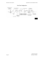
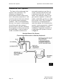
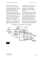
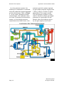
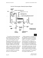
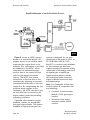
The recommended fuel train
consists of three primary
components (fuel filter, pressure
regulator(s), and shut-off valve) in
addition to the supply piping that is
used to transport gas from the fuel
source to the engine inlet. The
recommended configuration to be
used for Caterpillar gas engines can
be seen in figure 1.
The customer is responsible for
providing a fuel train that delivers
fuel to the engine that meets the
guidelines for the specific engine and
application. Proper configuration of
the fuel train including the selection
of all components prior to the engine
including but not limited to the
supply piping, pressure regulators,
fuel filter and gas shutoff valve will
provide the required fuel pressure
to the engine inlet while keeping
pressure fluctuations within the
limits for the engine (see price list).
Supply Piping
Although the supply piping is not
part of the engine’s fuel handling
system, it is a primary component
of the overall system; it supplies the
gaseous fuel to the engine gas inlet
connection. This supply piping must
be designed to deliver the fuel flow
rate required by the engine with a
minimum of restriction. A fuel supply
system with inadequate pipe
Page 2
diameter and/or too many bends in
the piping can pose a restriction to
flow that will come into play at
higher load operating conditions,
when the fuel demand is greatest.
If a fuel system is restrictive under
steady-state conditions, the engine
will be unable to achieve its full
power potential because the fuel
system cannot deliver the necessary
amount of fuel to the cylinders. Even
piping that is capable of adequate
fuel flow at full rated power may
experience restrictions under
transient conditions. When an engine
experiences a sharp increase in load,
the change requires a corresponding
increase in fuel flow. A poorly
designed fuel supply system can
resist this demand for increased fuel
flow, causing the engine to struggle
to take on the increased load.
The gas supply system can
facilitate engine servicing by
including strategically placed
blocking valves. Blocking valves
are used to manually shut off gas
flow to parts of the system while
components are being serviced or
replaced. In some situations,
blocking valves may be required
by industry convention or code.
The following are important rules
of thumb for the design of a proper
gas supply system, however you
should consult applicable industry
guidelines and standards for any
limitations that apply for each
specific project:
•
Pressure relief valves should
be placed along the piping
©2008 Caterpillar®
All rights reserved.