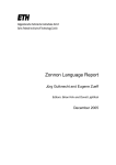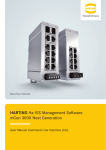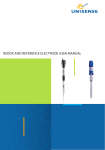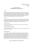
1
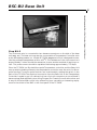
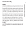
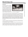
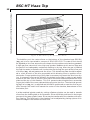
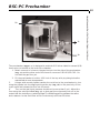
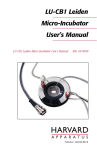
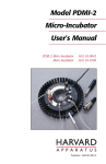
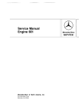
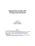
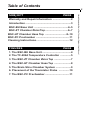
Table of Contents
1
PAGE
Warranty and Repair Information ........................2
Introduction ............................................................3
BSC-BU Base Unit ............................................4–5
BSC-ZT Chamber Zbicz Top ..............................6–7
BSC-HT Chamber Haas Top ............................8–10
BSC-PC Prechamber ............................................11
Cleaning Instructions............................................12
FIGURES
PAGE
1. The BSC-BU Base Unit ......................................4
2. The TC-202A Temperature Controller ..............5
3. The BSC-ZT Chamber Zbicz Top ......................7
4. The BSC-HT Chamber Haas Top ......................8
5. The Brain Slice Chamber System ....................9
6. Placement of the Thermistor Probe ..............10
7. The BSC-PC Prechamber ................................11
Harvard Apparatus Brain Slice Chamber System User's Manual
SUBJECT
Warranty and Repair Information
Harvard Apparatus Brain Slice Chamber System User's Manual
2
Serial Numbers
All inquires concerning our product should refer to the serial number of the unit(s).
Warranty
Harvard Apparatus warranties the instrument(s) for a period of one year from date
of purchase. At its option, Harvard Apparatus will repair or replace the unit(s) if it
is found to be defective as to workmanship or material.
This warranty does not extend to damage resulting from misuse, neglect or abuse, normal wear and tear, or accident.
This warranty extends only to the original customer purchaser.
IN NO EVENT SHALL HARVARD APPARATUS BE LIABLE FOR INCIDENTAL OR
CONSEQUENTIAL DAMAGES. Some states do not allow exclusion or limitation of
incidental or consequential damages so the above limitation or exclusion may not
apply to you. THERE ARE NO IMPLIED WARRANTIES OF MERCHANTABILITY,
OR FITNESS FOR A PARTICULAR USE, OR OF ANY OTHER NATURE. Some states
do not allow this limitation on an implied warranty, so the above limitation may not
apply to you.
If a defect arises within the one-year warranty period, promptly contact Harvard
Apparatus, Inc. 84 October Hill Road, Holliston, Massachusetts 01746-1371
using our U.S. only toll free number 1-800-272-2775 or dial (508) 893-8999. Goods will
not be accepted for return unless an RMA (returned materials authorization) number
has been issued by our customer service department.The customer is responsible for
shipping charges. Please allow a reasonable period of time for completion of repairs,
replacement and return. If the unit is replaced, the replacement unit is covered only
for the remainder of the original warranty period dating from the purchase of the original device.
This warranty gives you specific rights, and you may also have other rights which vary
from state to state.
Repair Facilities and Parts
Harvard Apparatus stocks replacement and repair parts. When ordering, please
describe parts as completely as possible, preferably using our part numbers. If practical, enclose a sample or drawing.We offer a complete reconditioning service.
CAUTION: Not for clinical use on human patients.
Introduction
3
The Harvard Apparatus, Inc. brain slice chamber systems offer the investigator two
methods of maintaining thin slice of brain tissue in vitro. When used in conjunction
with a common base unit (BSC-BU), either the BSC-HT (Haas Top) or the BSC-ZT (Zbicz
Top) will maintain brain slice preparations for many hours and allow for stable intracellular or extracellular recording. The BSC-ZT is a full submersion chamber in which
solutions flow transversely to the cut surfaces of the slice. The BSC-HT is an interfacetype chamber in which one cut surface of the slice is exposed to a humidified gas mixture. The rapid exchange of inflowing solutions with each top unit allows for rapid
adminstration of drugs and changes in the extracellular ionic environment.
Harvard Apparatus Brain Slice Chamber System User's Manual
Congratulations! You have purchased one of the finest Brain Slice Chambers available
to aid you in your research. You will find the Harvard Apparatus, Inc. unit easy to use
and easy to maintain.
BSC-BU Base Unit
Harvard Apparatus Brain Slice Chamber System User's Manual
4
1f
Perfusion
Output Line
1e
Perfusion
Output Line
1d
Left Elbow
1c
Right Elbow
1a
1b
Banana
Connectors
Center Elbow
Figure 1. The BSC-BU Base Unit
The BSC-BU Base Unit
The BSC-BU Base Unit (Figure 1) is adaptable to both the BSC-HT (Haas Top) and the
BSC-ZT (Zbicz Top). The base unit consists of a double walled cylinder enclosing a
nichrome wire heating element as well as the tubing which carries the superfusing
solution to the top unit.
Step BU-1
When using the BSC-HT the cylinder must be filled with distilled water. When using
the BCS-ZT either distilled water or mineral oil may be used. If there is a chance that
both the BSC-ZT and BSC-HT will be used, distilled water should be placed in the cylinder as it would be necessary to clean the mineral oil from the gas dispenser tubes
before the BSC-HT could be used.
Step BU-2
There are three right angle elbow fittings located on the bottom of the base unit’s double walled cylinder. The center elbow (Fig. 1b) is used to bubble a 95% O2/5% CO2
mixture through distilled water during operation with the BSC-HT; it is not used with
the BSC-ZT. The right and left hand elbows are each intended to be connected to the
drug(s) being studied. The drug applied to the right hand elbow (Fig. 1c) will flow
out of the right hand tube at the top of the cylinder and along the right hand chambers of the Haas Top; the drug applied to the left elbow (Fig. 1d) flows from the left
tube at the top of the cylinder and along the left hand chamber of the Haas Top. When
using the BSC-ZT, only the right elbow is used; care should be taken to plug the center elbow so that fluid within the BSC-BU does not leak out.
BSC-BU Base Unit
5
Step BU-3
The nichrome wire is connected to two banana connectors on the side of the base
unit (Fig. 1a). The base unit may also be connected to a Temperature Controller such
as the Harvard Apparatus, Inc. Model # TC-202A (Figure 2) which is designed to maintain the perfusate temperature within ±0.2oC.The resistance of the nichrome wire is
approximately 2 ohms should the researcher choose another method of applying current. The power source should be capable of delivering approximately 2.5 amps.
Since the TC-202A is a Bi-polar/Mono-polar Temperature controller, and the Base Unit
uses a resistive heating element, the temperature controller must be set to its Monopolar function.The mono-polar function can be achieved by setting the switch in the
back of the TC-202A.The electrical connection from the Base Unit to the Temperature
Controller is made by an I/O cable which has a 6 pin din connector at one end and 2
banana plugs (Red and Black) plus a Ring Tongue (for Chassis Ground) at the other end
A way to minimize 60Hz noise is by referencing your recording or measuring equipment to the shield of the BNC in the front panel of the TC-202A.
Harvard Apparatus Brain Slice Chamber System User's Manual
Figure 2. TC-202A Temperature Controller
BSC-ZT Zbicz Top
Harvard Apparatus Brain Slice Chamber System User's Manual
6
3c
3b
3a
Figure 3. The BSC-ZT Zbicz Top
The BSC-ZT (Figure 3) is a submersion type chamber in which brain slices are supported on a stiff nylon mesh to allow the perfusing solution to flow transversely across
both cut surfaces.
Step ZT-1
To assemble the slice chamber using the BSC-ZT, position the top unit so that one of
the clear plastic tubes protruding through the top of the base unit (Fig. 1e or 1f) can
be connected to the fitting on the bottom of the BSC-ZT (Fig. 3a) and the top can be
centered on the BSC-BU. After this connection has been made, place the top unit onto
the base unit. Although the top unit is machined to fit into the round opening at the
top of the base unit, it is recommended that dental wax or some easily removed adhesive (e.g. rubber cement) be used to secure the top unit. In addition two screw holes
and two screws have been provided to secure the BSC-ZT to the base unit.
BSC-ZT Zbicz Top
7
An opening has been drilled through the side of the top unit (Fig. 3b) for placement
of a thermistor probe (BSC-T2) near the outflow hole at the end of the trough. The
thermistor probe is inserted through the luer fitting at the side of the top unit and positioned so the thermistor is in the middle of the trough.
Slices in the BSC-ZT can be held on the mesh by a number of methods. As the perfusing solution flows transversely there is little tendency for slices to move vertically.
Therefore, slices can be held at a few points that allow for stable recording with microelectrodes. Slices can be held to the mesh with stimulating electrodes, the plastic
insert (Fig. 3c) or other wire holders. The number of points at which a slice is immobilized depends on the size of the tissue. For example, guinea pig hippocampus
(approximately 3 x 6 mm) is stable when held at 4 points while smaller slices may
require only 2 or 3 points. Slices can also be held by covering them with a piece of
fine nylon net which can be purchased at a fabric store.
A wide mouthed pipette, made by cutting the tapered end off a Pasteur pipette, can
be used to transfer slices to the chamber. This procedure should be done with the
solution flow stopped. When transferring slices a fine bristled brush should be positioned between the mouth of the pipette and the end of the mesh nearer to the outflow dam. The brush can then be used to position the slice. Immediately before starting the solution flowing, place a few drops of the perfusing solution on the slice so
that the chamber is filled. This will prevent surface tension from lifting the slice, a
result when the chamber fills from the side. A flow rate of 1 ml/min may suffice at
room temperature while warmer temperatures will require higher flow rates. To
insure even flow through the chamber, a nylon mesh (similar to the mesh supporting
the slice) can be positioned between the inflow port and the support mesh. A newly
cleaned chamber may "slurp", that is, fluid will alternately build up then flow over the
dam. If this occurs, place a piece of tissue paper or cotton thread at one edge of the
dam to act as a wick
Step ZT-3
The investigator is to supply the necessary electrical ground. The ground device (agar
bridge or Ag/AgCl wire) should be positioned between the end of the mesh and the
outflow dam to prevent disruption of fluid flow over the slice. Be aware that the position of the ground may effect the fluid level near the dam and thus the fluid level of
the chamber.
Harvard Apparatus Brain Slice Chamber System User's Manual
Step ZT-2
BSC-HT Haas Top
Harvard Apparatus Brain Slice Chamber System User's Manual
8
4a
4f
4b
4c
4d
4e
Figure 4. The BSC-HT Haas Top
The BSC-HT (Figure 4) is an interface-type chamber which provides rapid fluid
exchange and stability for intracellular recordings. Slices rest on elastic nylon mesh
around which a thin sheet of physiological saline flows by capillary action. Slices are
oxygenated by a warmed and humidified mixture of 95%O2,/5%CO2, which flows
across the top surface of the slice. (A flow rate of 0.5 ml/min. is recommended).
Step HT-1
To assemble the BSC-HT, position the top unit so the two clear plastic tubes protruding through the top of the base unit (Fig. 1c and 1d) can be connected to the two fittings on the bottom of the BSC-HT (Fig. 4a). After these connections have been made,
place the top unit onto the base unit. Although the top unit is machined to fit into the
round opening at the top of the base unit, it is recommended that dental wax in addition to the two nylon hold-down screws, be used to secure the top unit.
BSC-HT Haas Top
9
An opening has been machined
through the side of the top unit (Fig.
4b) for placement of a thermistor
probe near the inflow port. The thermistor probe is inserted through the
luer fitting. It should be fully inserted so that the thermistor tip is positioned near the center of the groove
designed to accommodate it. Slices
rest on elastic nylon mesh (pantyFigure 5.
hose type) which must be installed
The BSC-BU with BSC-HT, BSC-ZT and BSC-PC
by the investigator along the bottom
surface of the green plastic frames which are supplied (see Figure 6).
To mount the nylon mesh,cut a piece of mesh approximately 5 x 11 cm.Gently stretch
one end of the mesh under the side of the green plastic frame with the milled out
channels and push the frame and mesh into the groove of the BSC-HT. The frame
should be above the mesh and positioned on the horizontal portion of the groove. The
small circles cut in the frame (Fig. 4d) are the prechambers and should be positioned
above the inflow ports (farthest from the lip of the chamber) (Fig. 4e). The remaining mesh should hang over the lip of the top unit. Cut the section of mesh which
hangs over the edge to form a point. The solution leaving the chamber will drip from
this point. Alternatively, it is possible to use a smaller piece of nylon mesh under the
frame and use a second piece of mesh or tissue paper to carry solution over the lip of
the chamber.
The BSC-HT is designed so that the effects of two drugs can be studied simultaneously-one drug flowing down the left side of the chamber and the second down the right.
Intermixing has been found to be negligible.
Once assembled, the chamber is connected to the sources of perfusing solution by the
luer fittings located at the bottom of the base unit. Flow rates of 0.5 mil/min per
chamber can be obtained by keeping the solutions in bottles pressurized to approximately 0.2 kg/CM2 by a 95% O2/5% CO2 gas mixture. Electronically switched valves
are recommended for solution changes to minimize disruption of solution flow.
Harvard Apparatus Brain Slice Chamber System User's Manual
Step HT-2
BSC-HT Haas Top
Harvard Apparatus Brain Slice Chamber System User's Manual
10
6d
6e
6a
6f
6a
6c
6b
Figure 6. Placement of the Thermistor Probe
The bubblier port, the center elbow on the bottom of the chamber base (BSC-BU)
(Fig. 1a), is to be connected to a source of 95% O2/5% CO2. The rate of flow should
be adjusted so the flow across the slice keeps the top surface moist and oxygenated.
A high gas flow rate which is too high may produce bubbles which are too large and
the gas will be inadequately moistened, resulting in drying. After the gas is bubbled
through the water in the base unit, it enters the top through the port at the inflow end
of the top (Fig. 4f) and passes over the slices. The slotted top plate should be adjusted to cover as much of the slice as possible while allowing room to position microelectrodes. Proper positioning of this plate is necessary to prevent the slice from drying. If necessary, holes can be drilled in the slotted cover plate in order to gain better
access to the slice. Also, a piece of filter paper should be inserted between the cover
plate and the top of the chamber. This is to prevent water droplets from accumulating on the inside of the cover plate and dropping onto the slice. The electrical ground,
Ag/AgCl wire (Fig. 4c), is supplied and should be positioned as near the slice as possible, through the insert hole nearest the center of the chamber, downstream of the
thermistor port.
A wide mouthed pipette, made by cutting a Pasteur pipette, can be used to transfer
slices from the holding bath to the chamber. Slices should be positioned in the longer
grooves of the green plastic frame. Slices may be transferred to the chamber with solution flowing. The fluid level in the chamber can be adjusted by placing a piece of tissue at the edge of the frame to act as a wick.
BSC-PC Prechamber
11
7c
7a
Figure 7. The BSC-PC Prechamber
The prechamber (Figure 7) is designed to maintain 8-12 slices viable for several (6-8)
hours prior to transfer to the brain slice chamber
1. Attach one end of a hose to the gas inlet port on the side of the prechamber
(Fig. 7a) and the other end of the hose to a source of 95% O2/5% CO2. Do
not start the gas flow yet.
2. Fill the prechamber to within 1/16 inch of the top with physiological saline
maintained at room temperature.
3.
Using a wide mouth pipette, transfer the cut slices to the prechamber by lowering the pipette into the large opening at the top (Fig. 7b) to the proximity of the
nylon mesh and release the slice into the mesh.
4.
Turn on the gas (input pressure should not be more than 5 psi). Adjust the
flow using the valve provided (Fig. 7c) so that gas flows vigorously but not to the
extent that the turbulence causes spillage.The bubbling gas oxygenates the saline
and creates a circular fluid flow which continuously enriches the slices.
Harvard Apparatus Brain Slice Chamber System User's Manual
7b
Cleaning Instructions
Harvard Apparatus Brain Slice Chamber System User's Manual
12
Run distilled water through the chamber and perfusion lines after every use. Water
should not be allowed to remain in the perfusion lines or chamber as this promotes
bacterial growth. Removing the water by a gentle vacuum will decrease the number
of times cleaning is needed. The BSC chamber should be periodically cleaned by passing 100-200 ml of 1N HCI through both the base unit and the top unit being used.
Immediately after the acid wash, 200 ml or more of distilled water should be run
through the system.
DO NOT allow the HCI solution to remain in the chamber. DO NOT use the organic
solvents, including ethanol, to clean the chamber as these substances can damage
components and seals.
Other cleaning agents such as Ter-g-A-Zyme made by Alconox can be used. This is a
concentrated, anionic detergent with protease enzyme for manual and ultrasonic
cleaning. Excellent for removal of proteinaceous soils, tissue, blood, and body fluids
from glassware, metals, plastic, ceramic, porcelain, rubber and fiberglass with no interfering residues. Ideal as a cleaning agent in Reverse Osmosis and Ultra-Filtration
Systems. USDA authorized. Dilute 1:100. pH 9.5