1
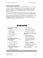
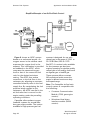
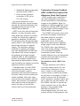
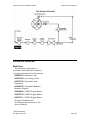
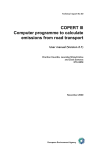
APPLICATION AND INSTALLATION GUIDE
GASEOUS FUEL SYSTEMS
G3600
G3500
G3400
G3300
Contents
Gaseous Fuel Systems............................................................ 1
Gas Engine Fuel System Components................................... 2
Supply Piping................................................................. 2
Flexible Connection .................................................... 3
Shut-Off Valve............................................................... 3
Filter/Coalescer .............................................................. 4
Pressure Regulators ........................................................ 7
Fuel-Air Mixer ................................................................ 8
Throttle......................................................................... 9
Fuel Systems Equipment for Special Conditions................... 10
Fuel Heater.................................................................. 10
Ferrous Fuel System ..................................................... 10
Corrosive Fuel System .................................................. 10
Fuel Accumulator ......................................................... 11
Carbureted Fuel Systems .................................................. 12
Gas Differential Pressure Regulator ................................ 13
Load Adjustment Valve ................................................. 14
Carburetor-Mixer .......................................................... 14
Deltec Carburetor ..................................................... 14
Impco Carburetor ..................................................... 16
High- and Low-Pressure Carbureted Fuel Systems ........... 17
Dual Gas Fuel Systems ................................................. 19
Air/Fuel Ratio Control Systems (AFRC) ............................... 21
General Description ...................................................... 21
Simple Feedback AFRC (High- and Low-Pressure
Carbureted Systems with Exhaust Oxygen Sensor) ......... 21
Combustion Sensing Feedback AFRC (G3600
Prechamber/Gas Admission Valve Fuel System)............... 23
Gas Admission Valve (GAV) Fuel System.................... 23
Enriched Prechamber Combustion System .................. 24
G3600 Fuel System and AFRC .................................. 24
Reference Materials .......................................................... 25
Media List ................................................................... 25
Foreword
This section of the Application and Installation Guide generally describes
Gaseous Fuel Systems for Caterpillar® engines listed on the cover of this
section. Additional engine systems, components and dynamics are addressed
in other sections of this Application and Installation Guide.
Engine-specific information and data are available from a variety of
sources. Refer to the Introduction section of this guide for additional
references.
Systems and components described in this guide may not be available or
applicable for every engine.
Information contained in this publication may be considered confidential.
Discretion is recommended when distributing. Materials and specifications
are subject to change without notice.
CAT, CATERPILLAR, their respective logos, “Caterpillar Yellow” and the
POWER EDGE trade dress, as well as corporate and product identity used
herein, are trademarks of Caterpillar and may not be used without
permission.
Application and Installation Guide
Gaseous Fuel Systems
Gaseous Fuel Systems
The fuel system on a gas engine is a highly specialized set of components
that must deliver the correct amount of fuel to the cylinder at the precise
moment it is needed. A well-designed fuel system enables the engine to
produce maximum power at peak efficiency with a minimum amount of
exhaust emissions.
This section discusses the components that make up a typical gas engine
fuel system and how they work together to accomplish the mission stated
above. It further discusses variations on these basic fuel systems that allow
gas engines to deliver optimized performance while operating under
challenging conditions, outlining the advantages, disadvantages and special
considerations that accompany each system.
SECTION CONTENTS
Gas Engine Fuel System
Components ....................... 2
• Supply Piping
•
Carburetor-Mixer
•
High- & Low-Pressure
Carbureted Fuel Systems
•
Shut-Off Valve
•
•
Dual Gas Fuel Systems
Filter Coalescer
•
Pressure Regulator
•
Fuel-Air Mixer
Air/Fuel Ratio Controlled Fuel
Systems ........................... 21
• General Description
•
Throttle
•
Simple Feedback AFRC
(High- & Low-Pressure
Carbureted Fuel Systems
with Exhaust Oxygen
Sensor)
•
Combustion Sensing
Feedback AFRC (G3600
Prechamber/Gas Admission
Valve Fuel System)
Fuel Systems Equipment for
Special Equipment ..............10
• Fuel Heater
•
Ferrous Fuel System
•
Corrosive Fuel System
•
Fuel Accumulator
Carbureted Fuel Systems .....12
• Gas Differential Pressure
Regulator
•
Reference Materials............ 25
Load Adjustment Valve
©2008 Caterpillar®
All rights reserved.
Page 1
Gaseous Fuel Systems
Application and Installation Guide
Gas Engine Fuel System Components
The typical gas engine fuel
system is comprised of several
main components that serve a role
in providing reliable fuel-air mixing
in response to the engine’s
performance needs.
The recommended fuel train
consists of three primary
components (fuel filter, pressure
regulator(s), and shut-off valve) in
addition to the supply piping that is
used to transport gas from the fuel
source to the engine inlet. The
recommended configuration to be
used for Caterpillar gas engines can
be seen in figure 1.
The customer is responsible for
providing a fuel train that delivers
fuel to the engine that meets the
guidelines for the specific engine and
application. Proper configuration of
the fuel train including the selection
of all components prior to the engine
including but not limited to the
supply piping, pressure regulators,
fuel filter and gas shutoff valve will
provide the required fuel pressure
to the engine inlet while keeping
pressure fluctuations within the
limits for the engine (see price list).
Supply Piping
Although the supply piping is not
part of the engine’s fuel handling
system, it is a primary component
of the overall system; it supplies the
gaseous fuel to the engine gas inlet
connection. This supply piping must
be designed to deliver the fuel flow
rate required by the engine with a
minimum of restriction. A fuel supply
system with inadequate pipe
Page 2
diameter and/or too many bends in
the piping can pose a restriction to
flow that will come into play at
higher load operating conditions,
when the fuel demand is greatest.
If a fuel system is restrictive under
steady-state conditions, the engine
will be unable to achieve its full
power potential because the fuel
system cannot deliver the necessary
amount of fuel to the cylinders. Even
piping that is capable of adequate
fuel flow at full rated power may
experience restrictions under
transient conditions. When an engine
experiences a sharp increase in load,
the change requires a corresponding
increase in fuel flow. A poorly
designed fuel supply system can
resist this demand for increased fuel
flow, causing the engine to struggle
to take on the increased load.
The gas supply system can
facilitate engine servicing by
including strategically placed
blocking valves. Blocking valves
are used to manually shut off gas
flow to parts of the system while
components are being serviced or
replaced. In some situations,
blocking valves may be required
by industry convention or code.
The following are important rules
of thumb for the design of a proper
gas supply system, however you
should consult applicable industry
guidelines and standards for any
limitations that apply for each
specific project:
•
Pressure relief valves should
be placed along the piping
©2008 Caterpillar®
All rights reserved.
Application and Installation Guide
downstream of the regulator
when allowed. Proper venting/
ducting for gases passing
through the relief valve will
need to be installed.
•
Careful attention should be
paid to connection types for
components. Use adapters
where necessary.
•
Always design with supply
piping at least as large in
diameter as the engine gas
inlet connection. Using a
larger pipe diameter allows
a greater margin of safety
against the supply system
being restrictive.
Minimize bends and diameter
changes in the fuel flow path
near the engine, especially
downstream of the engine's
gas pressure regulator. All
changes in direction (bend,
elbows, etc.) and changes in
diameter (expansions and/or
reductions) represent a
restriction to gas flow that
must be taken in to account.
•
•
Account for pipe diameter,
valves, elbows, and other
irregularities in the supply
piping by computing an
estimate of the system
restriction in advance of
engine installation. You
should be able to verify
through such calculations
that the supply pressure
and flow requirements of
the engine will be available
at the engine’s gas supply
inlet or you should redesign
the supply system.
©2008 Caterpillar®
All rights reserved.
Gaseous Fuel Systems
•
Make certain gas supply
piping is clean and free from
debris and liquids.
Flexible Connection
The connection between the
installation gas supply piping and
the engine gas inlet is an important
junction. Because the engine is
subject to vibration during operation,
the gas inlet connection can move
relative to the fixed piping of the
installation. Using a rigid joint at this
connection forces the vibration to be
taken up in the supply piping itself,
leaving open the possibility of metal
fatigue and failure resulting in a
dangerous leak of flammable gas.
This is easily addressed by using a
flexible connection between the
engine and supply piping.
Flexible connections for gaseous
fuels must be suited to this service.
They should be compatible with
hydrocarbon gases and any other
constituents found in the local fuel
supply, including corrosive gases
such as hydrogen sulfide, if present.
They should also be suited to high
temperatures that are possible to a
limited degree during normal operation
of the engine, but also in the event of
a fire. Most flexible connections used
for gas service use a stainless steel,
single braided, annular corrugated
flexible metal hose.
Shut-Off Valve
The gas shut-off valve (GSOV) is
one of the most important safety
device in the fuel system. Its role is
to allow gas to the engine only when
the engine is ready to use the gas. If
the engine is not operating, or if the
Page 3
Gaseous Fuel Systems
engine control has indicated it
should shut down, the GSOV
positively blocks the gas supply line
to stop gas flow.
The GSOV can be as simple a
device as a manually operated ball
valve. However, most modern
engines include automated safety
systems that require direct control
of the GSOV, so electrically driven
solenoid-actuated valves are used
for this purpose. Electrical power to
operate these valves may come from
on-engine sources (“self-powered”
valves) or from an external power
supply such as a set of batteries.
Caterpillar requires that the GSOV
be defaulted to the shut down
condition, requiring actuation to
allow gas flow (an “energize-to-run”,
or ETR system). Different safety
system design requirements may
require that the GSOV be actuated to
shut off flow (an “energize-to-stop”,
or ETS system), however this method
is not recommended or supported by
Caterpillar. If external powered is not
available at the site, the self-powered
GSOV must be used.
During normal operation of the
engine, using the start-stop switch,
GSOVs open and close as signaled by
the engine control. Under these
(normal stop) conditions, the ignition
system is left active to fire the spark
plugs while the engine runs down.
This helps to burn fuel in the fuel lines
between the GSOV and combustion
cylinder, preventing fuel from being
pumped into the exhaust system.
In an emergency shut down, the
GSOV is closed and the ignition
system is grounded immediately.
Page 4
Application and Installation Guide
This is done to stop rotation of the
engine as quickly as possible, but it
can leave unburned fuel in the engine
and exhaust system. This unburned
gas poses a hazard at restart in that it
can be ignited by hot exhaust gases
leaving the engine, resulting in an
exhaust stack explosion.
CAUTION: Always purge the
exhaust system after an emergency
shut down to avoid potential
exhaust system explosions due to
unburned fuel in the exhaust stack.
Purging the fuel from the exhaust
system can be accomplished by
cranking the engine while keeping
the gas shut off valve closed and
ignition system inactive.
GSOV type and size can be found
in the engine price list. The typical
mounting location of the GSOV is
upstream of the gas pressure
regulator, close to the engine. If the
GSOV supplied by Caterpillar is not
used, the customer supplied GSOV
must be able to perform in a similar
manner, acting to shut off the fuel
immediately after the signal is given.
Filter/Coalescer
Gas engines, like most engines,
require a fuel supply free from dirt
and other foreign matter (including
water). Foreign materials are
understandably common to gas
flows coming directly from the well,
but even pipeline gas can pick up
dirt, metal shavings, or weld slag
left behind from pipeline
construction, or scale and rust that
develop in the pipeline during use.
©2008 Caterpillar®
All rights reserved.
Application and Installation Guide
Left in the gas stream, particles and
liquids can adversely affect engine
performance or damage engine
internal components, leading to
reduced service life. Undesirable
solids and liquids are removed from
the gas stream using filters and
coalescers.
Gas filters supplied by Caterpillar
are designed to remove 99% of all
the particles larger than 1 micron in
diameter. Filters capable of removing
even smaller particles may be
required for sites with a high content
of sub-micron debris. It is the
customer’s responsibility to provide
clean, dry fuel to the engine.
Expenses for damage caused by
debris and abrasives in the fuel
system are not warrantable.
Gas filters are not designed to handle
liquids. Liquids in the fuel supply must
be removed using equipment designed
for that purpose. Bulk removal of
liquids, such as de-watering at the
well, is done with a scrubber. A
scrubber is a large tank that slows the
gas down, allowing miniscule droplets
to fall out of the gas flow more easily.
Mesh screens in the gas flow give
smaller droplets a surface on which to
collect, improving removal efficiency.
The bottom of the tank serves as a
collection basin for any liquids that fall
out. Removal of very fine liquids from
the gas stream is accomplished using
a coalescer. A coalescer accomplishes
this separation by causing smaller
droplets of liquid to form larger
droplets, which then gather on
©2008 Caterpillar®
All rights reserved.
Gaseous Fuel Systems
the surface of a filter and run off as
collected liquid. Gas systems that
include scrubbers and coalescers
must have provisions for draining
and disposing of the collected liquids.
Gas filters restrict the flow of gas
in the supply line and must be
included in supply restriction
calculations. To ensure proper
pressure at the gas pressure
regulator, the fuel pressure supplied
to the fuel filter must be equal to the
requirement at the pressure regulator
plus the maximum restriction of the
fuel filter and pipe restriction
between the pressure regulator and
fuel filter. Monitoring filter restriction
during use is made possible by
placing pressure taps or gauges both
upstream and downstream of the
filter. The pressure drop measured
in this manner can serve as an
indication of the condition of the
filter and whether or not it is time
to change the filter element.
Figure 1 shows a typical fuel filter
installation schematic for a Caterpillar
gas engine. Consult the price list for
fuel filters for specific engine models.
When using fuel filters not provided
by Caterpillar, always size the filter
based on the minimum fuel line
pressure and highest expected flow.
Fuel flow for each engine model can
be determined from the technical data
sheet for the specific engine and
rating and should be adjusted for fuel
consumption tolerance and changes
in the energy content of the fuel.
Page 5
Gaseous Fuel Systems
Application and Installation Guide
Fuel Train Configuration
Figure 1
Page 6
©2008 Caterpillar®
All rights reserved.
Application and Installation Guide
Example:
Determine the fuel flow of a G3516
LE 8:1 C/R engine rated at 943 BkW
(1265 bhp) at 1400 rpm, 54°C
(130°F) Separate Circuit Aftercooling
(SCAC) when operating on 33.4
MJ/Nm3 (850 btu/ft3) LHV fuel.
Fuel flow from TMI data:
291.5 Nm3/hr @ 35.57MJ/Nm3 LHV fuel
Gaseous Fuel Systems
•
•
•
(10,863 ft3/hr @ 905 Btu/ft3 LHV fuel)
Determine Energy Flow Rate:
Energy Flow Rate =
291.5 Nm3/hr x 35.57MJ/Nm3 = 10,369 MJ/hr
•
(10,863 ft3/hr x 905 Btu/ft3 = 9,831,015 Btu/hr)
Determine Fuel Flow at 33.4
MJ/Nm3 (850 Btu/ft3):
•
3
Fuel Flow at 33.4 MJ/Nm =
10,369 MJ/hr / 33.4 MJ/Nm3 = 310.4 Nm3/hr
Fuel Flow at 850 Btu/ft3 =
9,831,015 btu/hr / 850 btu/ft3 = 11,566ft3/hr
Determine Fuel Flow for Sizing Filter
with 5% Tolerance on Fuel Flow:
Fuel Flow for Filter Sizing =
310.4 Nm3/hr x 1.05 = 325.9 Nm3
(11,566 ft3/hr x 1.05 = 12,144 ft3/hr)
Gas filters should be installed
according to the manufacturer’s
recommendations and installation
guidelines. Some rules of thumb for
a successful filter installation include:
•
Note the flow direction
indicated on the filter cap
when installing the filter.
Incorrect installation will
©2008 Caterpillar®
All rights reserved.
cause a higher pressure drop
across the filter and result in
improper operation.
Mount the filter vertically and
as close to the engine as
possible.
Position the filter so there is
adequate room for servicing.
The upstream pressure tap
should be a minimum of 5 pipe
diameters from the filter inlet
and the downstream tap should
be a minimum of 10 pipe
diameters from the filter outlet.
Pipe unions can be installed to
simplify removal of the filter
housing, but they should not
be located between the
pressure measuring points.
Install a valve to vent the filter
for maintenance. This valve
should be connected to a pipe
to route the vented gas away
from the engine and any other
possible ignition sources. All
venting installation should
meet codes for disposal of
flammable gas.
Pressure Regulators
The gas pressure regulators controls
the supply of fuel to the on-engine
fuel system. This is a critical role in
support of the fuel system because
the fuel metering done by the fuel
system often depends directly on the
pressure of the fuel supply. To fulfill
its role in the system, the gas
pressure regulators must:
•
Step gas pressure down to a
value appropriate for the fuel
mixing equipment, and
Page 7
Gaseous Fuel Systems
Application and Installation Guide
•
Dampen out any fluctuations in
the supply pressure to stabilize
the supply to the mixer.
As with gas filters and other
components in the gas stream,
the proper regulator for a given
application depends on the specific
installation, including details such
as gas specific gravity, temperature,
pressure, flow rate, and desired outlet
pressure. All applications require at
least an engine pressure regulator,
which is used to maintain the
appropriate pressure to the engine
fuel inlet. In addition certain
applications will require a second
pressure regulator also known as a
knockdown regulator prior to the fuel
filter to decrease the pressure from
the fuel supply to a level that is less
than or equal to the maximum outlet
pressure of the engine pressure
regulator. If the external supply
pressure is too high to accomplish the
desired pressure reduction in a single
step (high pressure gas on a low
pressure package), or if the pressure
fluctuations in the external supply are
too large, a knockdown pressure
regulator may be required prior to
the fuel filter to deliver the desired
gas pressure to the engine pressure
regulator. As was stated for gas
filters, gas pressure regulators
should be installed according to the
manufacturer’s recommendations and
installation guidelines. Some rules of
thumb for a successful gas pressure
regulator installation include:
•
Page 8
To prevent pressure buildup
(“dead head” condition) avoid
providing gas inlet pressures
above the maximum
downstream pressure rating
for a regulator.
•
Install the regulator in the
correct gas flow direction and
downstream of the fuel filter.
• Piping to the gas regulator
must be at least as large as
the regulator inlet/outlet ports.
• The regulator should be
positioned so there is a length
equivalent to three pipe
diameters of straight pipe
upstream and downstream
from the regulator.
• The pressure regulator must
be adjusted at the engine
installation site.
As noted above, the gas pressure
regulator works closely with the
fuel-air mixer to make the fuel
system function properly. The gas
pressure regulator set-up should be
matched to the needs of the fuel-air
mixer and engine requirements. The
recommended configuration to be
used for Caterpillar gas engines can
be seen in figure 1. Additionally
Caterpillar recommends that each
package has its own dedicated
engine pressure regulator. An engine
pressure regulator should not be
used for multiple engines.
Gas pressure regulators are
configured to deliver various
pressures for various engines. Table 1
shows the various gas pressure
requirements for the G3300, G3400,
G3500 and G3600 engines.
Fuel-Air Mixer
The fuel-air mixer is the heart of a
gas engine fuel system. The mixer
meters the proper fuel flow rate to
©2008 Caterpillar®
All rights reserved.
Application and Installation Guide
match engine operating conditions to
simultaneously meet the demands of
engine power, load acceptance, and
exhaust emissions while accounting
for the impact of ambient air
temperature and pressure and gas
quality.
Perhaps the most widely used
device to accomplish this function is
the carburetor, which uses the inlet
airflow to gauge the proper amount
of fuel to admit for current operating
conditions. Systems that are more
complex actively monitor the
conditions of the incoming fuel and
air streams to make possible other
fuel-air mixing schemes; some of
these schemes will be described
later in this section.
Gaseous Fuel Systems
Throttle
The throttle is not directly a part of
the fuel system, but it has a direct
influence on the fuel system so it is
appropriate for this discussion.
The throttle is the device that
regulates engine performance by
controlling the flow of air (or fuel-air
mixture) to the cylinders. It typically
takes the form of a butterfly valve in
the inlet air system and is mounted as
close to the cylinders as the engine
design will allow. Because the throttle
regulates airflow, it is directly
responsible for one of the most
important inputs to the fuel system.
The airflow rate combined with the
desired air/fuel ratio determines the
fuel flow rate that the fuel system
must provide to meet the current
engine operating conditions.
Gas Supply Pressure Requirements*
Minimum
Pressure
kPa (psig)
Maximum
kPa (psig)
G3300
Low Pressure Gas
High Pressure Gas
10 (1.5)
83 (12)
69 (10)
172 (25)
G3400
Low Pressure Gas
High Pressure Gas
10 (1.5)
138 (20)
35 (5)
172 (25)
10 (1.5)
41 (6)
35 (5)
83 (12)
207 (30)
241 (35)
172 (25)
14 (2)
380 (55)
276 (40)
276 (40)
207 (30)
69 (10)
1034 (150)
G3500
Low Pressure Gas, Impco
Low Pressure Gas, Deltec
High Pressure Gas
Low Emission 11:1 C/R
Low Emission 8:1 C/R
Standard TA
Naturally Aspirated
G3600
* Supply pressure to the fuel regulator.
Table 1
©2008 Caterpillar®
All rights reserved.
Page 9
Gaseous Fuel Systems
Application and Installation Guide
Fuel Systems Equipment for Special Conditions
Gas engines are frequently placed
in service where prevailing conditions
place special demands on fuel system
performance. For many of these
situations, special equipment can
be incorporated into the fuel system
to adjust for special conditions.
heater. Similarly, the fuel lines
between the fuel heater and the
engine should be insulated to
minimize heat loss. The heater
should be located upstream of the
gas pressure regulator to avoid any
impact on gas supply pressure.
Fuel Heater
Ferrous Fuel System
Many fuel metering-mixing
schemes rely on a volume-to-volume
basis for properly matching fuel flow
to airflow. Unfortunately, air and gas
volumes are directly dependent upon
temperature, making the
temperature of the inlet gas an
important parameter for proper fuel
system operation. Also, hydrocarbon
fuel gas streams are typically made
up of a mixture of many different
hydrocarbon gas fractions, each
with their own qualities. Many of
the heavier fractions tend to exist
as liquids at lower temperatures,
making control of fuel stream
temperature an important tool in
preventing the unwanted dropout
of hydrocarbon liquids in the fuel
delivery system.
There are many applications for
gas engines where the installation
environment is considered hazardous
due to the possible presence of an
explosive gas-air mixture. Because fire
is a threat, special rules are applied
that tailor the devices and materials
used in that area to minimize their
contribution to the fire hazard. The
fuel system is one of the areas on the
engine that can get special attention
under these conditions.
To resolve these issues, it is
possible to install a heat exchanger
in the fuel delivery system to serve
as a fuel heater. The most
convenient source for heat for such
a device is the jacket water system
on the engine. Because fuel heaters
are required only under extreme
circumstances, they should be
mounted as close to the engine as
possible to minimize any change in
temperature after the gas leaves the
Page 10
For hazardous environments, some
engine models have an available
option for a “ferrous” fuel system,
in which certain components of the
standard fuel system are replaced
with similar parts made from ferrous
materials (iron or steel). The ferrous
materials can withstand higher
temperatures than other common
materials such as aluminum.
Corrosive Fuel System
Materials hazardous to fuel system
components are not all from external
sources. Certain gas streams can
carry a significant amount of
corrosive compounds that can
damage the fuel system. For these
situations, certain gas engine models
offer a corrosive fuel system option
©2008 Caterpillar®
All rights reserved.
Application and Installation Guide
as part of an overall engine
operation strategy to accommodate
the potentially damaging effects of
corrosive compounds in the fuel gas.
A corrosive fuel system is modified
in a manner that replaces any
components susceptible to corrosive
attack with similar parts made of
less vulnerable materials. Materials
to be removed include the so-called
“bright” metals, like aluminum and
copper. Of course, given that the
fuel and air are mixed prior to
entering the cylinders on many
engine configurations, any other
components on the engine that are
exposed to the gas must also be
modified or replaced with more
robust substitutes. Components
such as the aftercooler (on engines
with pre-turbocharger fuel-air
mixing) must be tailored to the
corrosive presence in the fuel gas.
Corrosive components remaining in
©2008 Caterpillar®
All rights reserved.
Gaseous Fuel Systems
the gas after combustion must also
be addressed. Elevated jacket water
temperatures may be used to help
keep the corrosive compounds from
condensing out of the blowby gases
in the crankcase. The allowable
limits for corrosive compounds in
the fuel are described in the Gaseous
Fuels section of the Application &
Installation Guide.
Fuel Accumulator
Some situations such as landfill or
biogas applications may provide
additional challenges with varying gas
pressures and/or energy content being
supplied to the fuel train. In these
instances and accumulator tank may
need to be installed to help provide
a buffer to minimize these variations
that the fuel train and engine may
see and to keep the fluctuations
within the limits of the engine.
Page 11
Gaseous Fuel Systems
Application and Installation Guide
Carbureted Fuel Systems
The heart of the carbureted fuel
system is the carburetor. The
carburetor is designed to
mechanically monitor airflow and
mix in the proper proportion of fuel
to achieve the air/fuel ratio desired
for a specific engine operating
condition. This is accomplished by
the use of a venturi, a narrowing in
the airflow path that creates a
pressure drop in the flow. Because
the properties of this pressure drop
are predictable, it can be used to
create controlled conditions for
accurately metering a gas flow to
create a fuel-air mixture flow with
a desired air/fuel ratio. As noted
earlier, the carburetor relies on the
gas pressure regulator to deliver a
stable, predictable gas flow to make
this process work. Also included in
the system is a load adjustment
valve that allows for fine-tuning the
system’s mixing properties to match
the prevailing conditions at each
installation. A general schematic of
a carbureted fuel system is shown
in Figure 2.
Standard Natural Gas System
(Turbocharged-Aftercooled or Naturally Aspirated)
Figure 2
Page 12
©2008 Caterpillar®
All rights reserved.
Application and Installation Guide
Gas Differential Pressure
Regulator
In a carbureted fuel system, the
gas pressure regulator is set up to
function as a differential pressure
regulator. A differential pressure
regulator doesn’t necessarily
maintain a constant gas pressure.
Its goal is to maintain a constant
gas pressure differential relative
to the static pressure of the airflow
at the inlet to the carburetor-mixer.
As air pressure to the carburetor
increases, fuel pressure is
Gaseous Fuel Systems
maintained equal to air pressure plus
the gas differential pressure. The gas
differential pressure is typically set
to 1.0 to 1.3 kPa (4 to 5 inches of
water) by adjustment of the spring
acting on the diaphragm inside the
regulator. This constant differential
pressure allows the carburetor to
adjust its air/fuel ratio mixing to
accommodate a wide range of
engine operating points based on
their air demand.
A typical gas differential pressure
regulator is shown in Figure 3.
Typical Gas Differential Pressure Regulator
Figure 3
©2008 Caterpillar®
All rights reserved.
Page 13
Gaseous Fuel Systems
When the forces on both sides of
the diaphragm are the same, the
regulator sends gas to the carburetor
at a constant rate. The balance line
between the regulator and carburetor
must be in place to maintain the
proper force balance. A turbocharged
engine will not develop full power
with the balance line disconnected.
With proper adjustment of the spring,
gas pressure to the carburetor will
always be greater than carburetor
inlet air pressure, regardless of load
conditions or turbocharger boost
pressure. Gas differential pressure
regulators have flow capacities based
on supply pressure to the regulator,
body size and internal orifice size. Gas
supply pressure requirements for each
engine family are shown in Table 1
earlier in this section.
Load Adjustment Valve
The load adjustment valve is a
variable orifice in the fuel line
between the carburetor-mixer and
the differential pressure regulator
as shown in Figure 4. Its purpose
is to provide a means to fine-tune
the air/fuel ratio setting of the fuel
system for site ambient conditions
and fuel quality. It does this by
throttling the gas flow delivered
by the gas differential pressure
regulator; lowering the gas pressure
relative to the airflow in the
carburetor will produce a leaner
mixture and vice versa. The valve
can only effect changes within a
certain range of adjustment.
However, the specific range covered
by a given fuel system set-up can be
altered by changing the carburetor
internal components to shift the fuel-
Page 14
Application and Installation Guide
air mixing characteristics. These
larger changes in air/fuel ratio are
accomplished by changing the gas
valve-and-jet combination in the
Impco carburetor or the venturi in
the Deltec carburetor. Such largescale changes in the carburetor are
typically tied to the lower heating
value of the fuel gas. The load
adjustment valve is typically used
to dial-in the selected fuel system
for site conditions.
Carburetor-Mixer
The carburetor-mixer’s main
function is metering and mixing
the fuel and air prior to entering the
combustion chamber. Proper mixing
depends on the carburetor being
sized for the appropriate fuel and the
fuel being supplied to the carburetor
at the proper pressure. Caterpillar
uses a Deltec or an Impco carburetor
to properly mix and meter gas fuels.
Deltec Carburetor
Figure 4 shows the venturi-type
(Deltec) carbureted fuel system
used on Caterpillar gas engines.
The venturi carburetors are
manufactured by Deltec and are
used on some low-pressure gas
engines. Venturi carburetors operate
on the venturi effect which, simply
stated, says that as air flows
through a venturi its pressure is
lower in the venturi (P2 in Figure 4)
than it is upstream (P1 in Figure 4).
The higher the airflow, the greater
the differential pressure will be. If,
at the same time, the gas pressure
to the carburetor (P3 in Figure 4) is
held constant with respect to P1,
the pressure differential P3-P2 will
increase as airflow increases. Any
©2008 Caterpillar®
All rights reserved.
Application and Installation Guide
Gaseous Fuel Systems
increase or decrease in this
differential pressure will cause a
corresponding change in fuel flow.
The gas pressure regulator is used to
keep the pressure difference
between P3 and P1 constant.
exhaust emissions are a necessity
since emissions will change with
changes in mass air/fuel ratio.
Depending on carburetor design,
emissions can vary throughout the
load range.
Engine power and emissions
setting are determined by the mass
air/fuel ratio entering the combustion
chamber. A carbureted system,
however, maintains a fixed volume
ratio of air and fuel, and therefore
does not maintain constant
performance with changes to air
temperature, fuel temperature or fuel
composition. This is particularly
important in applications where low
Note: Most engines come standard
with natural gas carburetors which
are designed for fuels with lower
heating value ranges from 31.4 to
55.0 MJ/Nm3 (800 to 1400 Btu/scf).
The price list also defines the
heating values ranges for optional
carburetors. If the fuel to be used
does not fall within the heating value
ranges specified, consult the factory
for assistance in carburetor sizing.
Cross Section of a Typical Deltec Carburetor-Mixer
Figure 4
©2008 Caterpillar®
All rights reserved.
Page 15
Gaseous Fuel Systems
Impco Carburetor
Figure 5 is a cross section of a
typical Impco carburetor mixer. This
system is used on all high-pressure
carbureted gas applications and
some low-pressure carbureted gas
applications. As air flows past the
carburetor diaphragm vacuum port,
a vacuum is created. This vacuum
is sensed by the air valve diaphragm,
which in turn raises or lowers the
gas valve as the airflow increases or
decreases accordingly. This allows
the carburetor to adjust the fuel flow
in proportion to airflow. The gas
valve and jet are sized for specific
fuel and operating condition ranges.
For example, a carburetor containing
Application and Installation Guide
a gas valve and jet sized for natural
gas would not operate properly on
landfill gas. Likewise, operation with
a three-way catalyst requires a
different valve and jet than operation
with no catalyst. It is very important
that the engine is equipped with the
proper valve and jet.
Note: Contact Caterpillar for proper
application of these valves and jets.
The air/fuel ratio is adjusted by
setting the regulator differential
pressure and the load adjustment
valve. Instructions for correctly
adjusting the air/fuel ratio can be
found in the service manuals.
Cross Section of Typical Impco Carburetor–Mixer
(600 Series Varifuel Mixer – Cut-Away)
Figure 5
Page 16
©2008 Caterpillar®
All rights reserved.
Application and Installation Guide
High- and Low-Pressure
Carbureted Fuel Systems
The components involved in a
carbureted fuel system remain
largely the same regardless of how
the system is adapted to a given
engine design. However, the nature
of the design does dictate certain
operating attributes of the fuel
system. One of those attributes is
the operating fuel pressure range.
Simply due to the placement of
the carburetor relative to the
turbocharger in the air system,
the carbureted fuel system can
be configured as a high- or lowpressure system.
Gaseous Fuel Systems
In a high-pressure fuel system,
fuel-air mixing is done downstream
of the turbocharger, after the inlet
airflow is boosted. Refer to Figure 6.
Because of this ordering of
components (carburetor after
turbocharger), the fuel system must
be able to deliver the fuel gas to the
carburetor at a higher pressure than
that of the boosted air stream;
anything lower and the fuel cannot
be forced to flow into the air stream.
High-pressure gas fuel systems
operate on gas supply pressure
ranging from 140 kPa (20 psig) to
280 kPa (40 psig) depending on the
engine model.
High-Pressure Gas Carbureted Fuel System
Figure 6
©2008 Caterpillar®
All rights reserved.
Page 17
Gaseous Fuel Systems
In a low-pressure system, the
ordering of components is reversed,
with the carburetor located upstream
of the turbocharger. Refer to Figure
7. In this order (carburetor before
turbocharger), the carburetor does
not have to manage the boosted air
stream, so fuel supply pressure
requirements are much lower. Low-
Application and Installation Guide
pressure gas fuel systems operate
on gas supply pressure ranging from
7 kPa (1 psig) to 70 kPa (10 psig)
depending on the engine model.
The low-pressure system is often
used in situations where gas supply
pressures at a particular site are
limited, either by building code or
by the gas supply source itself.
Low-Pressure Gas Carbureted Fuel System
Figure 7
Page 18
©2008 Caterpillar®
All rights reserved.
Application and Installation Guide
Dual Gas Fuel Systems
It is possible to set up a gas engine
to run on two very different gaseous
fuels. Such an arrangement is
known as a dual gas fuel system.
Dual gas fuel systems are typically
put into service for gas streams with
very different heating values, such
as landfill/digester gas and natural
gas or natural gas and propane. Dual
gas fuel systems allow an engine the
flexibility to use fuel streams that
may not always be available because
the second fuel source serves as a
backup for the first.
A simple dual gas setup uses two
gas pressure regulators feeding into a
single carburetor; this type of system
is shown in Figure 8. The primary fuel
in a two-regulator system is always
the lower energy content gas of the
two (see Table 2). This makes it
possible to tune both fuel streams
by adding a second load adjustment
valve in the supply line from the
backup regulator. In this way,
the primary fuel stream is tuned at
the adjustment valve on the
carburetor inlet and the secondary
fuel stream is tuned at the secondary
adjustment valve.
The following guidelines are given
for automatic switching between the
primary and secondary fuels for the
following combinations.
Primary Fuel
Secondary Fuel
Digester
Natural Gas
Natural Gas
Propane
Gaseous Fuel Systems
In each of these systems, the
primary fuel is the low Btu fuel
and the secondary fuel is the high
Btu fuel.
Note: Dual regulator systems for
digester-propane are not
recommended. The engine will be
difficult to start due to the negative
pressure required to obtain the
correct air fuel ratio on propane.
Dual regulator systems can
transfer between the primary and
secondary fuel while under load.
It is recommended that the fuel
regulators not be moved from the
factory mounting. Any increase in
fuel line length can cause problems
with smooth transfer between the
primary and secondary fuel. The
solenoid operated shutoff valves
should be energized to run, and be
mounted as close to the fuel
regulators as possible. During normal
operation on the primary fuel, both
solenoid valves should be engaged.
The primary fuel gas, supplied by
low Btu regulator, is always at a
greater pressure than the secondary
fuel supplied by high Btu regulator;
therefore, when the primary fuel is
present, the secondary regulator will
shut off the secondary fuel, even
though the solenoid valve is
energized.
Table 2
©2008 Caterpillar®
All rights reserved.
Page 19
Gaseous Fuel Systems
Application and Installation Guide
Dual Fuel Turbocharged or Naturally Aspirated Engines
Figure 8
To transfer to the secondary fuel,
de-energize the low Btu solenoid
valve. As the primary fuel is used
in the fuel line between the low
Btu pressure regulator and the
carburetor-mixer, the pressure in the
line will drop. As this gas pressure
becomes negative, the secondary
regulator will sense the drop and
open to supply secondary fuel to the
carburetor. Circuits that attempt to
switch from primary to secondary
fuel by flip-flopping the solenoid
valves are usually not successful
and are not recommended.
Page 20
Another approach to providing dual
gas capability involves putting two
complete fuel systems on the same
engine. In this type of arrangement,
each fuel system is tuned in the
normal manner. The challenge with
this arrangement is finding space to
fit in two sets of fuel metering and
mixing equipment. Dual fuel systems
with regulators and mixers for each
fuel can be automatically switched,
but the engine must be at no load.
These systems will require a flip-flop
solenoid arrangement. If switching
fuel supplies under load is a
©2008 Caterpillar®
All rights reserved.
Application and Installation Guide
requirement, a programmable
controller is required to control
switching from one fuel to another.
The time delays for the solenoid
values will need to be determined
at the site for changeover. For
automatic switching between
primary and secondary fuel, a dual
timing magneto or EIS is required.
Place the activation switch for the
Gaseous Fuel Systems
dual timing between the primary
fuel solenoid and the primary fuel
regulator. As long as primary fuel
pressure is supplied to the engine,
the timing will be in the advanced
position. Once the primary fuel
pressure is lost, the ignition will
index for operation on the secondary
fuel.
Air/Fuel Ratio Control Systems (AFRC)
General Description
Air/fuel ratio controlled (AFRC)
engines take mixing of fuel and air
one step further than simple
carbureted systems. While the
carburetor is capable of adjusting the
fuel mixing rate to match different
airflow rates, it can only sense the
volume flow rate of air and fuel. It
cannot account for the effects of
temperature on the density of air
and gas; nor can it account for other
factors, such as changes in humidity
or in fuel heating value.
Simple Feedback AFRC
(High- and Low-Pressure
Carbureted Systems with
Exhaust Oxygen Sensor)
Air/fuel ratio control offers the
ability to maintain a specific level
of NOx emissions even when there
are changes in load, fuel heating
value or ambient conditions. Real
©2008 Caterpillar®
All rights reserved.
measuring and adjusting for all of
the factors that affect combustion
would require an incredibly complex
and impractical control system.
Instead of measuring multiple
parameters of the incoming fuel
and air, AFRC systems monitor key
output parameters that provide a
direct measure of how closely
combustion matches the desired
condition. This approach is known
as closed-loop feedback control. In
AFRC systems, the most commonly
used feedback parameter is the
amount of oxygen in the exhaust
stream because it tells how much
oxygen was left after the fuel was
burned. Because most, if not all,
of the oxygen in the combustion
chamber comes from the air in the
inlet charge, exhaust oxygen levels
are a direct result of the air/fuel ratio
being provided.
Page 21
Gaseous Fuel Systems
Application and Installation Guide
Simplified Example of an Air/Fuel Ratio Control
Figure 9
Figure 9 shows an AFRC system
based on a carbureted engine. An
oxygen sensor in the exhaust stack
measures the oxygen level in the
exhaust. This information is provided
as feedback to the AFRC, which
compares the measured oxygen
level to that of the correct air/fuel
ratio for the desired emissions
setting. The AFRC then makes
corrections to the fuel flow in the
carburetor by adjusting an actuatorcontrolled butterfly valve in the fuel
supply line. By manipulating the fuel
pressure being supplied to the
carburetor, the AFRC can dial in the
air/fuel ratio that is correct for the
engine setting under the prevailing
operating conditions.
Caterpillar offers exhaust oxygen
feedback systems for several leanburn gas engine models. The version
available for high-pressure gas fuel
Page 22
systems is designed for use with
natural gas in the range of 33.41 to
50.12 MJ/Nm3 (850 to 1275
Btu/SCF). A version is also available
for low-pressure gas lean-burn
engines operating on pipeline-quality
natural gas or low-energy fuels such
as digester gas or landfill gas.
These systems deliver constant
NOx emissions levels across the
engine’s defined continuous-duty
load-speed range.
Note: The Caterpillar air/fuel ratio
control system is compatible with
the following:
•
Customer Communication
Module (CCM, gas engine
version).
•
Woodward load share
interface module (PWM
version).
©2008 Caterpillar®
All rights reserved.
Application and Installation Guide
•
Woodward digital synchronizer
and load control (DSLC).
•
Fisher suction pressure
controllers (4-20 mA or
0-15 psi output).
For more information on the
G3500 air/fuel ratio control system,
consult the Systems Operation and
Troubleshooting sections of the
G3500 Service Manual.
AFRC is not only used for lean-burn
engines. It is also necessary when
using three-way catalytic converters.
In order for a three-way catalyst to
operate as designed, the NOx and
CO emissions must be approximately
equal, which in turn requires that the
air/fuel ratio be kept at a specific
setting. This emissions setting is
achieved by operating the engine
at a near-stoichiometric air/fuel ratio,
with about 0.5% excess oxygen in
the exhaust. An exhaust oxygen
feedback AFRC is well equipped to
monitor this exhaust oxygen level
and make the adjustments to air/fuel
ratio that allow the catalyst to provide
optimum emissions reduction.
Caterpillar does not offer AFRC
systems from the factory for use
with stoichiometric engines
operating with three-way catalysts;
however, these control systems are
widely available. Note that when
using a three-way catalyst with the
Impco fuel systems, the carburetor
valve and jet must be changed to
match the type of air/fuel ratio
control device you have selected.
©2008 Caterpillar®
All rights reserved.
Gaseous Fuel Systems
Combustion Sensing Feedback
AFRC (G3600 Prechamber/Gas
Admission Valve Fuel System)
AFRC systems aren’t restricted to
use with carbureted fuel systems,
nor are they limited to using exhaust
oxygen as the feedback signal. An
example of a different approach is the
combustion sensing AFRC integrated
into the engine control strategy on the
G3600 family of gas engines.
The G3600 fuel system starts with
the same fuel supply components
described earlier for the same
reasons: to deliver a stable,
predictable source for fuel gas.
Beyond the gas pressure regulator,
things begin to look very different.
The G3600 uses a gas admission
valve fuel mixing strategy in support
of an enriched prechamber
combustion system. Both are
notably different from the carbureted
systems discussed above and thus
require some description.
Gas Admission Valve (GAV) Fuel
System
The gas admission valve (GAV)
is a much simpler device for fuel
mixing than a carburetor, but as
such, it relies on the supporting
control system to deliver the proper
air/fuel ratio to the engine. A GAV is
simply a valve in the air inlet path
that is opened or closed to allow fuel
gas to flow into the inlet airflow. On
the G3600, the GAV is cam-driven
and is located in the air inlet elbow
leading to each cylinder head.
Because the G3600 is a
turbocharged engine, the GAV fuel
system requires a high-pressure fuel
Page 23
Gaseous Fuel Systems
gas supply to allow the gas to flow
into the boosted inlet air stream.
Metering the fuel mixed into the
airflow requires precise
measurement of the pressure and
temperature of the air and gas
flows, coupled to timing of the
opening and closing of the valve.
Given a fixed differential pressure
of gas over air pressure, a specific
amount of gas could be mixed with
the air stream by controlling the time
duration that the GAV is open. The
G3600 system uses the opposite
approach, opening the GAV for a
fixed period of time and regulating
the gas-over-air differential pressure
to control fuel metering.
Enriched Prechamber Combustion
System
As air/fuel ratio becomes leaner,
the amount of energy required to
establish stable combustion
increases and, at some point, the
ability of a simple spark plug to
deliver sufficient energy becomes
impractical. An enriched
prechambered combustion system
uses a separate chamber outside the
main cylinder to start combustion.
The prechamber, with its own small
feed of fuel gas, provides a
controlled environment with a richer
air/fuel ratio that greatly improves
combustion conditions, and makes
it possible to operate the main
chamber mixture at the very lean
air/fuel ratio that enables the G3600
to produce very low NOx emissions.
G3600 Fuel System and AFRC
The G3600 fuel system is built
around a fuel rail delivering gas to
both the GAVs and the prechambers
Page 24
Application and Installation Guide
on each cylinder. Fuel flow through
the GAVs is timed by the camshaft
actuating each valve. Fuel flow to
the prechambers is controlled by a
check valve in the prechamber fuel
path that prevents fuel flow into the
prechamber when the main chamber
pressure is high. The main fuel rail is
regulated at the inlet by a fuel
control valve that manipulates the
gas pressure in the fuel rail. This fuel
control valve is driven according to
the engine’s desired and actual
speed signals as they are registered
at the engine control module.
A schematic of the G3600 fuel
system is shown in Figure 10.
To provide a feedback signal for
AFRC, the G3600 places a sensor
at the outer edge of the main
combustion chamber that detects
when the flame front of combustion
arrives. By measuring the time
interval between the firing of the
spark plug and the signal from the
combustion sensor, each cylinder
tells the main engine control about
combustion directly in the cylinder.
The engine control module combines
this information with data on the
temperature and pressure of both
the fuel and inlet air streams to
determine how to tailor the overall
engine air/fuel ratio to optimize
combustion. Adjustment of air/fuel
ratio is accomplished by
manipulating the turbo wastegate
and inlet air choke to control airflow;
more air delivered means a leaner
air/fuel ratio.
©2008 Caterpillar®
All rights reserved.
Application and Installation Guide
Gaseous Fuel Systems
Reference Materials
Media List
The following information is
provided as an additional reference
to subjects discussed in this manual.
LEBW4977: Gaseous Fuels
LEKQ7260: Low Energy Fuels
LEKQ7742: Detonation and
Preignition
LEKQ6378: Caterpillar Methane
Number Program
LEKQ9085: G3600 Engine Basics
LEKQ7518: G3500 Engine Basics
LEKQ7511: G3400 Engine Basics
Systems Operation and
Troubleshooting sections of the
Service Manual
©2008 Caterpillar®
All rights reserved.
Page 25
LEBW5336-01
©2008 Caterpillar®
Printed in U.S.A.
All rights reserved.