1
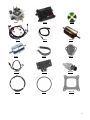
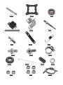
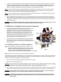
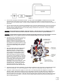
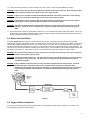
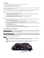
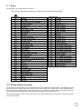
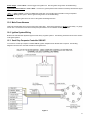
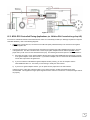
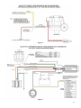
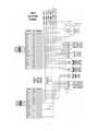
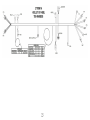
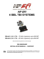
HP EFI 4 BBL TBI SYSTEMS 550-411 (900 CFM – 75 lb/hr injectors) up to 525 HP 550-412 (900 CFM – 85 lb/hr injectors) up to 600 HP NOTE: HP throttle body systems do not include fuel pump. TBI HARDWARE INSTALLATION MANUAL – 199R10507 NOTE: These instructions must be read and fully understood before beginning installation. If this manual is not fully understood, installation should not be attempted. Failure to follow these instructions, including the pictures may result in subsequent system failure. 1 TABLE OF CONTENTS: 1.0 INTRODUCTION ..................................................................................................................................................................... 3 2.0 CHOOSING THE RIGHT SYSTEM: ........................................................................................................................................ 3 3.0 WARNINGS, NOTES, AND NOTICES .................................................................................................................................... 4 4.0 PARTS IDENTIFICATION ....................................................................................................................................................... 4 5.0 ADDITIONAL ITEMS REQUIRED FOR INSTALLATION ......................................................................................................... 7 6.0 TOOLS REQUIRED FOR INSTALLATION .............................................................................................................................. 7 7.0 COOLANT TEMPERATURE SENSOR INSTALLATION ......................................................................................................... 7 8.0 REMOVAL OF EXISTING FUEL SYSTEM .............................................................................................................................. 7 9.0 HP EFI TBI SYSTEM INSTALLATION..................................................................................................................................... 8 9.1 Throttle Body........................................................................................................................................................................ 8 9.2 Throttle Connections ............................................................................................................................................................ 8 9.3 MAP Sensor Installation and Vacuum Line Connections..................................................................................................... 9 9.4 Fuel Pump, Fuel Line, and Filter Installation ....................................................................................................................... 9 9.5 Return Line Installation ...................................................................................................................................................... 11 9.6 Oxygen Sensor Installation ................................................................................................................................................ 11 9.6.1 Oxygen Sensor Mounting Procedure .......................................................................................................................... 12 10.0 Wiring .................................................................................................................................................................................. 13 10.1 Important Wiring “Do’s and Don’ts” ................................................................................................................................. 13 11.0 ECU Connectors and Pinout ............................................................................................................................................... 13 11.1 Pinout ............................................................................................................................................................................... 14 12.0 Primary Sensors Connection ............................................................................................................................................... 14 12.1 Throttle Position Sensor (TPS) ........................................................................................................................................ 15 12.2 Manifold Air Pressure Sensor (MAP) ............................................................................................................................... 15 11.3 Coolant Temperature Sensor (CTS) ................................................................................................................................ 15 12.4 Manifold Air Temperature Sensor (MAT) ......................................................................................................................... 15 12.5 Knock Sensor (Knock) ..................................................................................................................................................... 15 12.6 Wide Band Oxygen Sensor (WB02) ................................................................................................................................ 15 12.7 Fuel Pressure (Fuel) ........................................................................................................................................................ 15 12.8 Oil Pressure (Oil) ............................................................................................................................................................. 15 12.9 CANbus (CAN)................................................................................................................................................................. 15 13.0 Primary Outputs ................................................................................................................................................................... 15 13.1 Idle Air Control (IAC) ........................................................................................................................................................ 15 13.2 Fuel Injector Outputs (Injectors) ...................................................................................................................................... 16 13.3 Ignition Adapter (Ignition) ................................................................................................................................................. 16 14.0 Loose Wires ........................................................................................................................................................................ 16 15.0 Main Power Harness ........................................................................................................................................................... 17 16.0 Ignition System Wiring ......................................................................................................................................................... 17 16.1 Small Cap Computer Controlled GM HEI ........................................................................................................................ 17 16.2 NON- ECU Controlled Timing Applications (ex. GM Non-ECU Controlled Large Cap HEI) ............................................ 18 16.3 Magnetic Crank Pickup .................................................................................................................................................... 20 16.4 Hall Effect Crank Pickup .................................................................................................................................................. 21 17.0 Programmable Inputs and Outputs ...................................................................................................................................... 22 17.1 Inputs ............................................................................................................................................................................... 22 17.2 Outputs ............................................................................................................................................................................ 23 2 1.0 INTRODUCTION Holley Performance Products has written this manual for the installation of the HP EFI TBI fuel injection system. This manual contains the information necessary for the hardware installation. Please read all the WARNINGS, NOTES, and TIPS, as they contain valuable information that can save you time and money. It is our intent to provide the best possible products for our customer; products that perform properly and satisfy your expectations. Should you need information or parts assistance, please contact our technical service department at 1-270-781-9741, Monday through Friday, 8 a.m. to 5 p.m. Central Time. By using this number, you may obtain any information and/or parts assistance that you may require. Please have the part number of the product you purchased when you call. NOTE: This manual is for the hardware installation of a Holley Throttle Body Fuel Injection System and instructions specific to it. Instructions on wiring harness installation, software operation, sensor operation, and tuning is contained on the disc supplied with the HP systems. NOTE: A laptop computer with a USB port is required for the installation and tuning of the HP system. WARNING! The HP EFI systems consist of a number of sophisticated components. Failure of any one component does not constitute, nor does it justify, warranty of the complete system. Individual service items are available for replacement of components. If assistance is required or if you need further warranty clarification, you can call Holley Technical Service at the number shown above. WARNING! To preserve warranty, these instructions must be read and followed thoroughly and completely before and during installation. It is important that you become familiar with the parts and the installation of the HP EFI system before you begin. Failure to read and understand these instructions could result in damage to HP EFI components that are not covered by the warranty and could result in serious personal injury and property damage. WARNING! The oxygen sensor in this kit is recommended for use with ONLY unleaded fuel. Use of leaded fuels will degrade the oxygen sensor and will result in incorrect exhaust gas oxygen readings and improper fuel delivery. Failure to follow these directions does not constitute the right to a warranty claim. WARNING! Failure to follow all of the above will result in an improper installation, which may lead to personal injury, including death, and/or property damage. Improper installation and/or use of this or any Holley product will void all warranties. WARNING! Use of some RTV silicone sealers will destroy the oxygen sensor used with this product. Ensure the RTV silicone sealant you use is compatible with oxygen sensor vehicles. This information should be found on the RTV package. 2.0 CHOOSING THE RIGHT SYSTEM: To ensure that you have purchased the correct HP EFI kit for your application, check to be sure that the kit you purchased is listed beside your engine’s horsepower. NOTE: HP throttle body systems do not include fuel pump. HORSEPOWER KIT PART NUMBER Up to 525 hp ..................................550-411 HP EFI TBI, 900 CFM 75 lb/hr injectors Up to 600 hp ..................................550-412 HP EFI TBI, 900 CFM 85 lb/hr injectors 3 3.0 WARNINGS, NOTES, AND NOTICES WARNING! For the safety and protection of you and others, only a trained mechanic having adequate fuel system experience must perform the installation, adjustment, and repair. It is particularly important to remember one of the very basic principles of safety: fuel vapors are heavier than air and tend to collect in low places where an explosive fuel/air mixture may be ignited by any spark or flame resulting in property damage, personal injury, and/or death. Extreme caution must be exercised to prevent spillage and thus eliminate the formation of such fuel vapors. WARNING! This type of work MUST be performed in a well-ventilated area. Do not smoke or have an open flame present near gasoline vapors or an explosion may result. 4.0 PARTS IDENTIFICATION ITEM 1 2 3 4 5 6 7 8 9 10 11 12 13 14 15 16 17 18 19 20 21 22 23 24 25 26 27 28 29 30 31 32 33 34 DESCRIPTION TBI Assembly 700 CFM 65 lb/hr Complete TBI Assembly 900 CFM 72 lb/hr Complete TBI Assembly 900 CFM 85 lb/hr Complete HP EFI ECU HP EFI Software HP EFI TBI Wiring Harness HP EFI Communications Cable Metal Fuel Filter Fuel Filter (WIX 33033) Fuel Filter Clamp Fuel Pump Block-Off Plate & Gasket Wide Band Oxygen Sensor MAP Sensor Coolant Temperature Sensor Air Cleaner Adapter Air Cleaner Gasket Flange Gasket Manifold Flange Studs Heat Insulator Gasket Oxygen Sensor Weld Ring 40 AMP Relay (Pre-Installed in harness) Throttle Bracket Throttle and Cruise Control Stud Throttle Lever Ball Throttle Lever Bracket Ford kick down return spring Throttle Lever Stud Transmission Kickdown Stud Hose Clamp Grommet Cable Ties Tube Cap Lockwasher 1/4-28 Nut 5/16-24 Nut 5/16" Vacuum Line QTY 1 1 1 1 1 1 1 1 1 1 1 1 1 1 1 1 1 4 1 1 1 1 1 1 1 1 1 1 8 1 12 1 2 2 4 1 SERVICE PART 534-172 534-187 534-173 554-113 N/A 558-100 N/A 562-1 N/A N/A 12-813 554-101 538-24 534-2 17-14 108-4 108-10 N/A 108-12 534-49 534-26 N/A N/A N/A N/A N/A N/A N/A N/A N/A N/A N/A N/A N/A N/A N/A TBI Service Parts: Air Charge Temperature Sensor Fuel Injector 900 CFM 72/75 lb/hr (requires purchase of 4) Fuel Injector 900 CFM 85 lb/hr (requires purchase of 4) Fuel Pressure Regulator Diaphragm Idle Air Control (IAC) Motor Throttle Position Sensor (TPS) 1 1 1 1 1 1 534-46 522-80 522-43 512-1 543-105 543-29 Optional Parts: Small Cap GM HEI Ignition Adapter Ford TFI Ignition Adapter 1 1 558-304 538-305 4 Item 1 Item 4 Item 2 Item 5 Item 3 Item 6 Item 7 Item 8 Item 9 Item 10 Item 11 Item 12 Item 13 Item 14 Item 15 5 Item 16 Item 17 Item 19 (Pre-Installed in Harness) Item 20 Item 22 Item 32 Item 21 Item 23 Item 25 Item 28 Item 18 Item 24 Item 26 Item 29 Item 27 Item 30 Item 33 6 Item 31 Item 34 5.0 ADDITIONAL ITEMS REQUIRED FOR INSTALLATION 3/8" fuel hose (must meet SAE J30) 5/16" steel fuel line (must meet SAE J526) Tee fitting for fuel gauge 5/16" fuel hose (must meet SAE J30) 0-30 psi fuel gauge In addition to the above list, the engine must be equipped with a four barrel intake manifold and the vehicle must be in good operating condition. 6.0 TOOLS REQUIRED FOR INSTALLATION Standard wrench set Small blade screwdriver 5/32” Allen wrench Medium blade screwdriver #2 Phillips screwdriver Digital Volt-Ohm meter Drill and assorted bit sizes Hole saw (2”) Terminal crimping tool Utility knife Factory Service Manual for your vehicle Windows laptop (XP, Vista, 7) An assistant is necessary for some installation and adjustment procedures and should be present for safety reasons. 7.0 COOLANT TEMPERATURE SENSOR INSTALLATION The coolant temperature sensor (item 12) must be installed in a coolant passage in either the intake manifold or cylinder head. The sensor has 3/8” NPT threads. If only a ½” NPT port is available, an adapter will have to be used. It is best to drain the some of the coolant before the sensor is installed. 8.0 REMOVAL OF EXISTING FUEL SYSTEM 1. Disconnect the battery and remove the air cleaner. 2. Before disconnecting any vacuum hoses, it is a good idea to sketch out the vacuum hose routing. Using masking tape and a permanent marker, mark all the vacuum hoses, vacuum sources, and ports before removing the old fuel delivery system. 3. Remove and discard the fuel line that connects the fuel delivery system from the fuel pump. This will not be needed in the installation. 4. Disconnect and plug the inlet fuel line that runs from the gas tank to the fuel pump. This will prevent fuel spillage and foreign matter or dirt from entering the fuel line. DANGER! Before disconnecting or removing fuel lines, ensure the engine is cold. Do not smoke. Extinguish all open flames. An open flame, spark, or extreme heat near gasoline can result in a fire or explosion causing property damage, serious injury, and/or death. 5. The fuel delivery system can now be removed. Holley recommends removing the mechanical fuel pump, if so equipped, and blocking-off the fuel pump mount using the provided fuel pump block off plate. The HP EFI system kit includes a block-off plate that will fit small and big block Chevrolet and Chrysler engines. If the block-off plate does not fit your engine, a block-off plate may have to be purchased from a local performance parts supplier. 6. If required, replace the intake manifold at this time. Proceed to step seven if this is not required. A 4-BARREL STOCK OR AFTERMARKET SQUARE FLANGE INTAKE MANIFOLD IS REQUIRED FOR THE INSTALLATION OF THE HOLLEY HP EFI TBI system. 7. Place clean shop towels or rags into the manifold opening to prevent dirt or debris from entering the engine. Keep exposed ends of the vacuum and fuel lines free from dirt. WARNING! Failure to cover the intake opening with a clean towel could result in dirt or debris entering the engine. Dirt or debris in the induction system can cause engine damage, which may necessitate in a complete engine overhaul. 8. Remove all traces of the old gasket material from the TBI mounting flange. DO NOT gouge the intake manifold sealing surface during removal of old gasket material. Failure to remove all traces of the old gasket material will result in vacuum leaks that will be difficult to detect later. Sealing flanges must be clean and dry before installation. 9. Remove the shop towels from the intake and vacuum out the intake channel to ensure no dirt or debris is left in the intake system. Place a shop towel over the entire intake opening until you are ready to install the new HP EFI TBI. 7 9.0 HP EFI TBI SYSTEM INSTALLATION 9.1 Throttle Body NOTE: A 4 barrel intake is required for the installation of the Holley HP EFI TBI system. NOTE: Some GM and Chrysler engines require the use of a manifold adapter Holley Part Number 17-6. This adapts the spread bore carburetor manifold to the Holley square flange. 1. Install the heat spacer between the manifold and the 4 barrel throttle body injection unit. Check for sufficient thread engagement of the throttle body hold down studs and nuts. It may be necessary to purchase and install longer studs in the manifold for proper nut engagement. Gasket sealant may be used to ensure that no vacuum leaks occur. NOTE: If using a heat spacer, the flange gasket is not required. DANGER! Check for proper clearance between engine components, such as the distributor, coil, etc., and the throttle body. If any interference is found, correct the condition before continuing. Failure to do so can result in damage to the engine components or the throttle body. DANGER! Check for proper clearance between the air cleaner and the engine compartment cover hood. If any interference is found, correct the condition before continuing. Failure to do so can result in damage to the compartment cover or engine components. 2. Place the throttle body in position over the manifold flange studs with the IAC motor facing the front of the vehicle and the regulator/fuel connections towards the rear of the vehicle. 3. Tighten the throttle body down in a criss-cross pattern being careful not to over-tighten. Proper torque is 5-7 ft lbs. WARNING! Over tightening the TBI manifold flange hold-down-nuts may result in a warped or cracked throttle body. The TBI hold down nuts should be tightened down progressively in a criss-cross pattern to 5-7 ft./lbs., to prevent leaks and avoid causing damage to the throttle body. A TBI that has been damaged due to negligence of the owner will void the warranty. 9.2 Throttle Connections 1. Measure the length of the throttle lever arm on the carburetor removed from the vehicle. Compare the length of the existing throttle lever arm with the one on the HP EFI throttle body. If the two throttle lever arms are similar in length (within 1/2” of each other), the throttle lever arm hole on the HP EFI throttle body can be used without the extension bracket. Use the throttle lever arm extension bracket, if the old throttle lever arm is significantly longer than the new throttle lever arm. Before installation of the bracket, check the diameter of the throttle cable stud. Some systems may use a 1/4” stud that will require drilling of the appropriate hole in the extension bracket to a 1/4” diameter. Attach the extension bracket using two fillister head screws as shown in Figure 1. The extension lever length can be adjusted using the four sets of holes. 2. Attach throttle linkage and have an assistant get in the vehicle and fully actuate the throttle controls. Make the necessary adjustments to the throttle linkage to ensure that the throttle plates are vertical when the throttle control is wide open. Work the throttle linkage back and forth several times to ensure it operates smoothly with no binding or sticking. Figure 1 DANGER! Sticking throttle may result in uncontrolled engine or vehicle speed. This could cause property damage, personal injury, or death. A sticking throttle may be caused by improperly installed throttle cables, lack of clearance for any of the throttle linkage, or by a binding throttle linkage. Check all throttle cables for proper installation and alignment and actuate the throttle to check for any potential binding or clearance problems. Repair any problems before continuing. 8 3. Locate the 1/4-28 throttle stud from the parts provided and attach to the throttle lever with the nut provided. Connect the accelerator linkage to the throttle stud on the throttle body. If the vehicle is equipped with an automatic transmission, connect the transmission kickdown rod to the linkage on the throttle body. The transmission kickdown may have to be adjusted. Follow the vehicle manufacturer’s procedure for the correct adjustment procedure. NOTE: On late model GM and Ford overdrive transmissions, if the HP ECU is not being set up to control torque converter clutch lock up, a competent transmission shop must change the transmission electronic lockup to a mechanical lockup. Failure to do so will result in premature transmission failure. NOTE: On Chrysler vehicles, a lever extension will be needed, Holley Part Number 20-7. Van applications may require the use of throttle lever extension Holley Part Number 20-14. 4. Attach throttle linkage and throttle return spring. Have an assistant get in the vehicle and fully depress the accelerator pedal. Make the necessary adjustments to the throttle linkage to insure that the throttle reaches wide-open position when the accelerator is depressed. Work throttle linkage back and forth several times to ensure that it operates smoothly with no binding or sticking. DANGER! Failure to attach the throttle return spring or a sticking throttle may result in uncontrolled engine or vehicle speed, which could cause personal property damage, serious injury, or death. 9.3 MAP Sensor Installation and Vacuum Line Connections 1. The MAP sensor must be installed as close to the vacuum source it is connected to as possible. It must be connected to a “full manifold vacuum” port. This is a vacuum source below the throttle body plates. The throttle body has a full manifold port that the sensor can be connected to (see Figure 2). It is best not to “tee” multiple items into the port that supplies the MAP sensor. The sensor should be mounted such that the vacuum port on the sensor is pointed at some downward angle above the vacuum source so that moisture does not collect in the sensor itself. 2. Install vacuum hoses to the appropriate port on the throttle body. Use the diagrams made during removal of the existing fuel system to locate the correct port. The vacuum ports of the throttle body are labeled in Figure 2. 9.4 Fuel Pump, Fuel Line, and Filter Installation NOTE: HP Throttle Body systems DO NOT include a fuel pump. The installer can use their in-tank or in-line pump of choice. Holley offers in-line and in-tank EFI fuel pumps. P/N 12-920 is an inline pump rated for up to 600-650 HP naturally aspirated engines. It is the recommended in-line pump for Holley 4bbl TBI systems. NOTE: If you have dual fuel tanks, you must purchase Holley PN 534-38. The following section covers the installation of an in-line pump such as Holley PN 12-920. Holley includes both a pre and post filter with the HP TBI system. Both of these filters have “barbed” ends and are designed to connect to an EFI pressure rated rubber hose. They are not designed for “AN” style plumbing. 1. Do not mount the fuel pump higher than the lowest point of the fuel tank. 2. Make sure fuel tank is properly vented. DANGER! Never get under a vehicle supported only by a jack. Serious injury or death can result from vehicles falling off of jacks. Before working underneath a vehicle, support it solidly with jack stands. 3. Mount the electric fuel pump as close to the fuel tank outlet as possible with the bracket provided. Mounting the fuel pump in this manner will insure that the pump will prime easily and purge fuel vapors in the TBI quickly to ensure faster starts. DANGER! Take precautions to ensure that all fuel line routings are away from heat sources, such as the engine or exhaust pipes. A fire or explosion hazard could cause serious injury or death. DANGER! Ensure that the fuel pump mounting location will not interfere with any under the vehicle components, especially at the extreme limits of the suspension travel. A fire or explosion hazard could cause serious injury or death. 9 Figure 3 4. There are two metal filters included with the system. The filter marked “33033” MUST be installed between the fuel tank and the fuel pump inlet (unless an in-tank pump is used). The purpose of this filter is to protect the fuel pump from particles of dirt or other foreign material. The filter should be installed with the arrow on the filter pointing in the direction of the fuel flow. 5. The other metal fuel filter that is included with the EFI TBI system should be installed between the electric pump outlet and TBI unit. This is a 10 micron EFI filter. Position the filter, so the fuel hoses can be routed without kinks or sharp bends. The filter should be installed with the arrow on the filter pointing in the direction of the fuel flow. A clamp is provided to assist with mounting this filter in the kit. WARNING! Ensure both filters are installed in the proper direction. A flow direction arrow is stamped on the side of the filter to indicate the direction of fuel flow. Failure to do so will result in a system malfunction. DANGER! Take precautions to ensure all fuel line routings are away from heat sources, such as the engine or exhaust system. A fire or explosion hazard could cause property damage, serious injury, and/or death. 6. Plumbing must now be installed to connect the fuel tank to the filters, pump, and TBI unit. It is recommended to use steel hard line or stainless braided hose with AN fittings. If AN plumbing is used, the appropriate fittings must be purchased for the pump and TBI unit. Filters must have AN style fittings as well. The thread in the inlet and outlet fittings of the TBI unit is ¼” NPT. 7. 3/8” line should be used on the feed/pressure side of the system (the filters included are designed for 3/8” line). If using steel line, rubber hose (rated for use with fuel injection) can be used to connect the steel line to the pump and filters. You should not connect a rubber hose directly to a steel line unless the end of the line has a “bead/nipple” or barb that retains the hose (similar to the ends of the fuel filters). If the steel line is just cut off, purchase a compression fitting that a barbed hose end can be installed on, or use a tool to roll a bead/nipple on the end of the steel line. Install hose clamps on all of these junctions (8 are included in the kit). All fuel hoses used must meet SAE J30 performance standards. All steel fuel line must meet SAE J526 standards. 8. The TBI unit has an inlet and an outlet fitting. The inlet fitting is designed for a 3/8” hose and is on the drivers side (linkage side) of the throttle body. The return line (designed for a 5/16” hose) is on the passenger side (side with the TPS). 9. If you plan to install a fuel pressure gauge, do so at this time. The 4 bbl TBI systems are designed for an operating pressure of 21PSI. Although this is factory pre-set, it is ideal that it be checked. The TBI units have an 1/8 NPT plug on the drivers side that can be used to temporarily install a gauge (this location will interfere with the throttle cable on a permanent install) to set the pressure. Holley also sells a 0-100 PSI pressure transducer (PN 554-102) that plugs into the “fuel” connector on the main harness. This sensor can be installed anywhere between the fuel pump and the TBI unit. It has a 1/8” NPT male thread. 10 10. If using the existing fuel lines, inspect and replace any hose, clamps, or fuel line showing ANY sign of aging. DANGER! Failure to use a fuel hose that meets SAE J30 standards could result in fuel leaks. A fuel leak may result in a fire or explosion hazard, which could cause serious injury or death. DANGER! Failure to use a steel fuel line that meets SAE J526 standards could result in fuel leaks. A fuel leak may result in a fire or explosion hazard, which could cause serious injury or death. DANGER! Take precautions to ensure that all fuel line routings are away from heat sources, such as the engine or exhaust pipes. A fire or explosion hazard could cause serious injury or death. DANGER! Rigid fuel line tubing should be used for under vehicle runs, such as along vehicle frame rails or under floor pans. Failure to do so is a potential fire or explosion hazard, which could cause serious injury or death. 11. Anchor all fuel lines securely to solid chassis members at 1 ½ foot intervals using rubber coated steel clamps. Use of only approved steel fuel line tubing will afford maximum fuel line protection against road hazards and premature wearing due to flexing, temperature extremes, road salt, weather, etc. 9.5 Return Line Installation The Holley HP EFI TBI system requires a return fuel line to the fuel tank. Some late model vehicles that were originally equipped with a throttle body injection system may already have a return line to the fuel tank that can be utilized. If a return fuel line must be installed, a minimum size of 5/16” I.D. is recommended. The return line is on the passenger side of the TBI unit. The fitting on the TBI unit is designed for a 5/16 line. If a larger line is used, use an appropriate fitting on the throttle body. The return line must not present a pressure restriction to the return fuel flow. There should never be more than approximately 3 PSI of pressure in the return line. A line that is too small, or has restrictions will cause tuning problems with the system. DANGER! Do not use the vapor canister lines as a fuel return line. Possible fuel leaks may create a fire or explosion hazard, causing serious injury or death. WARNING! Use only approved steel fuel line. The return fuel line should enter the fuel tank at the “fuel level sending unit flange” or at the “filler neck”. The filler neck or sending unit must be removed from the tank to perform this operation. DANGER! Proper installation of the fuel return line may necessitate complete removal of the fuel tank. This work should be done by a fuel tank specialist, who regularly does this work and is familiar with safety regulations and precautions necessary to do this work. If a person attempts this work, who is not familiar with the safety regulations and precautions, an explosion hazard may result causing serious injury or death. Figure 5 9.6 Oxygen Sensor Installation The oxygen sensor should be mounted at a point where it can read a good average of all the cylinders on one bank. This would be slightly after all the cylinders merge. 11 9.6.1 Oxygen Sensor Mounting Procedure NOTE: Someone with experience in welding exhaust systems should install the oxygen sensor boss. Any competent exhaust shop will be able to perform this task at a minimum cost. WARNING! Use of leaded fuel will degrade an oxygen sensor. Prolonged use is not recommended unless periodic replacement is performed. WARNING! Use of some RTV silicone sealers will destroy the oxygen sensor used with this product. Ensure the RTV silicone sealant you use is compatible with oxygen sensor vehicles. This information should be found on the RTV package. 1. Locate a position for the oxygen sensor as close to the engine as possible. If your vehicle has catalytic converters, the oxygen sensor MUST be located between the engine and the catalytic converters. Figure 6 NOTE: The oxygen sensor should be mounted in such a way that the condensation in the exhaust tubing will not enter the 2 sensor. Mount the O sensor in the upper half of the exhaust tubing, with the angle “x”, shown above, being greater than 10°. The picture above indicates that the sensor can be mounted on either side of the exhaust tubing. 2. Drill a 7/8” hole in the location picked for the sensor. Weld the threaded boss into the 7/8” hole. Weld all the way around the boss to insure a leak proof connection. Install the oxygen sensor into the threaded boss and tighten securely. It is a good idea to add anti-seize to the threads to aid in removal. 3. On vehicles equipped with an AIR pump, the oxygen sensor must be mounted before the AIR injection into the exhaust, or the AIR pump must be disconnected. Holley recommends that if the AIR is injected into both exhaust manifolds, mount the oxygen sensor into the pipe immediately after the exhaust manifold. Disconnect the AIR pump tube from the exhaust manifold and plug both ends. Check with local ordinances for the legality of this procedure in your area. WARNING! Failure to disconnect the AIR pump or locating the oxygen sensor downstream from AIR injection will result in an extremely rich mixture, which could cause driveability problems and severe engine damage. WARNING! It is important that the distribution ring is properly installed and fastened to the throttle body. Failure to do so will cause an inadequate seal between the throttle body and air cleaner and may be a fire hazard in the event of a backfire. Fire hazard can result in property damage, serious injury, and/or death. 12 10.0 Wiring The following overviews how to properly install the wiring harnesses for this system. 10.1 Important Wiring “Do’s and Don’ts” An EFI system depends heavily on being supplied a clean and constant voltage source. The grounds of an electrical system are just as important as the power side. HP ECU’s both contain multiple processing devices that require clean power and ground sources. The wiring harnesses for them must be installed in such a manner that they are separated from “dirty” power and ground sources. DO’S Install the main power and ground directly to the battery. Keep sensor wiring away from high voltage or “noisy/dirty” components and wiring, especially secondary ignition wiring, ignition boxes and associated wiring. Use shielded/grounded cable that is supplied for wiring crankshaft and camshaft signals. Properly solder and heat shrink any wire connections. It is critical that the engine has a proper ground connection to the battery and chassis. DON’TS NEVER run high voltage or “noisy/dirty” wires in parallel (bundle/loom together) with any EFI sensor wiring. If wires need to cross, try to do so at an angle. Do not let Crank and Cam signal wiring near spark plugs and coil wires. Do not run non-shielded/grounded wire for crankshaft and camshaft signals, especially magnetic pickups. Do not run the USB Communications cable near or with any noisy wires. Do not exceed the current limits provided for the various outputs. If current levels exceed these, use the appropriate relay or solenoid drivers. Do not use improper crimping tools. Don’t use things like “t-taps”, etc. Use solder and heat shrink. It is never recommended to splice/share signal wires (such as TPS, etc) between different electronic control units. Don’t wire items that require “clean” ground or power to the same points. 11.0 ECU Connectors and Pinout Battery Power Connection – The HP ECU has a main battery power and ground connector on the right side of the ECU. The bottom position, Terminal “A” is the ground. The upper position, Terminal “B” is the positive terminal. Always use the fused power cable with the proper connectors supplied by Holley only. USB Communications Connector – HP ECU’s use a standard USB cable for Laptop communications Looking at the front, the connector is at the far left side. This connection is a common “mini USB” connector, typically used for digital cameras and other devices. Holley offers a USB cable with a sealed connector, PN 558-409 for applications where the USB cable will be plugged in, and the ECU is mounted in a dirty environment. HP ECU – The HP ECU has two main connectors: P1A - The first connector next to the USB connector is the “P1A” connector (34 pin). This connector is primarily an “Input” connector. It contains all the sensor inputs and wide band oxygen sensor control. P1B - The second connector is the “P1B” connector (26 pin). This connector is the “output” connector. It has 8 injector outputs, 8 DIS ignition outputs, 4 IAC outputs, and 4 user programmable outputs. Figure 7 13 11.1 Pinout The following is a pinout of the HP ECU connectors. The P1A and P1B connectors and pinout are identical for the HP and Dominator ECU's. P1A Connector Pin A1 A2 A3 A4 A5 A6 A7 A8 A9 A10 A11 A12 A13 A14 A15 A16 A17 A18 A19 A20 A21 A22 A23 A24 A25 A26 A27 A28 A29 A30 A31 A32 A33 A34 Function Coil - Input Fuel Pump Out (+12v) (10A Max) Input #2 (F52THG) Input #4 (F5G) TPS Input Points Trigger Output WB1 COMPR2 WB1 Shield WB HTR Switched +12v Input Manifold Air Temp Input Input #1 (F52THG) Input #3 (F5G) Cam/Crank Ground Gauge Digital Output WB1 COMPR1 WB1 VS-/IP+ Sensor Ground Engine Coolant Temp Input Oil Pressure Input Knock #2 Input Cam Sync Input / Ignition Bypass Output Map Sensor Input CAN Lo WB1 VS+ Sensor +5v NOT USED EST/Spout Output Knock #1 Input Crank Speed Input Fuel Pressure Input CAN Hi WB1 IP+ WB HTR + P1B Connector Pin Function B1 IAC A Lo B2 IAC A Hi B3 Output #4 (G P-) B4 Injector F Output B5 Injector G Output B6 Injector H Output B7 Injector E Output B8 IAC B Lo B9 IAC B Hi B10 Output #3 (G P-) B11 Output #2 (H P+) B12 Output #1 (H P+) B13 Injector D Output B14 EST Ground Output B15 EST 2 Output (Cylinder #2) B16 EST 4 Output (Cylinder #4) B17 EST 6 Output (Cylinder #6) B18 EST 8 Output (Cylinder #8) B19 Injector A Output B20 EST 12V Output B21 EST 1 Output (Cylinder #1) B22 EST 3 Output (Cylinder #3) B23 EST 5 Output (Cylinder #5) B24 EST 7 Output (Cylinder #7) B25 Injector C Output B26 Injector B Output 12.0 Primary Sensors Connection These sections are an overview of all the connections that must be completed on the “Main Harness”. The Main Harness is the primary harness that supports all the primary engine sensors, fuel and ignition for 8 cylinder engines, the #1 wideband oxygen sensor, and the four programmable input and output channels. There are two connectors for this harness designated as “P1A” (pin designations below that start with an A) and “P1B” (pin designations below that start with a B). The following descriptions indicate the name of the item and the name as labeled on the harness (each connector has a label) is shown in parenthesis. 14 12.1 Throttle Position Sensor (TPS) Connect to the TPS which is located on the throttle body. 12.2 Manifold Air Pressure Sensor (MAP) A 1 Bar MAP sensor is provided with all Holley EFI systems. Connect to the MAP sensor. 12.3 Coolant Temperature Sensor (CTS) Connect to the Coolant Temperature sensor which should have been installed in an engine coolant passage. 12.4 Manifold Air Temperature Sensor (MAT) Connect to the Air Temperature Sensor (see Figure 2). Multiport systems will have this installed in the intake manifold and TBI systems will have it installed in the throttle body air inlet. 12.5 Knock Sensor (Knock) Holley EFI systems work with either a one wire or two wire knock sensor. Application specific harnesses will have the correct knock sensor connections installed on the harness. A Universal harness comes with a 3 pin metripak connector. If a knock sensor is added, it should be connected into this connector 12.6 Wide Band Oxygen Sensor (WB02) Holley EFI systems can work with either a Bosch (PN 554-101) or NTK (PN 554-100) wide band oxygen sensor. These sensors must be purchased from Holley as they are calibrated specifically for use with Holley EFI systems. HP EFI systems are sold with the Bosch sensor. Make sure you have the proper sensor selected in the Engine Parameters area or sensor damage may occur. Connect the “WB02” connector to the WB02 sensor which should be installed in the exhaust system. 12.7 Fuel Pressure (Fuel) A fuel pressure transducer connector is pre-installed in the main harness. The system is plug-and-play configured for a Holley 100 PSI pressure transducer (can be purchased under PN 554-102). A different 0-5V transducer can be used, but the calibration must be set up as a custom sensor in the software. If these are not connected to a pressure transducer, the Fuel and Oil Pressure will read “LOW Err” in the data monitor. This will not cause any issues. NOTE: Connect to the transducer (if installed). 12.8 Oil Pressure (Oil) An oil pressure transducer connector is pre-installed in the main harness. The system is plug-and-play configured for a Holley 100 PSI pressure transducer (can be purchased under PN 554-102). A different 0-5V transducer can be used, but the calibration must be set up as a custom sensor in the software. If these are not connected to a pressure transducer, the Fuel and Oil Pressure will read “LOW Err” in the data monitor. This will not cause any issues. NOTE: Connect to the transducer (if installed). 12.9 CANbus (CAN) All harnesses have a CANbus communications connector. This is used to communicate with CANbus devices such as the Avenger Handheld tuning module or the 5.7” Touch Screen LCD. If these devices or any other CANbus device is not being used, there is no need to do anything with this connector. A24 CAN Lo (Pin B) A32 CAN Hi (Pin A) 13.0 Primary Outputs 13.1 Idle Air Control (IAC) Connect to the idle air control motor which is installed in the throttle body. 15 13.2 Fuel Injector Outputs (Injectors) All terminated harnesses have a fuel injector connector. Various fuel injector harnesses plug into this connector. It is essential these harnesses are used so that injector firing sequence is maintained. Note that for engines with different firing orders, you do NOT change these pins. The engine’s firing order is input in the software itself. V8 harnesses offered by Holley are labeled for GM, Ford, and Chrysler engines. Each injector harness has the engine cylinder number labeled on each injector connector. Connect each injector on the appropriate cylinder. 13.3 Ignition Adapter (Ignition) The Ignition Adapter connector contains all the wires needed to connect to adapter harnesses offered by Holley for various ignition systems and crank and cam sensor. The only ignition related wiring that is NOT contained on this connector is individual coil driver outputs for DIS applications. The adapter is pinned as follows: A30 – Crank signal Input - Both digital and inductive (proper type must be selected in the software) (Pin A) A22 – Cam signal Input / Ignition Bypass Output– Both digital and inductive (proper type must be selected in the software) NOTE: If using a computer-controlled GM HEI Distributor, this pin will serve as the ignition bypass output (Pin B) A14 – IPU Ground (Pin C) Chassis Ground – (Pin D) A10 – Switched +12v (Pin E) A27 – NOT USED (Pin F) A14 – IPU Ground (Pin G) A28 – EST/Spout Output (Pin H) A14 – Shield Ground (Pin J) A14 – Shield Ground (Pin K) NOTE: The crank and cam input wiring in both the main harness and adapter harnesses use a shielded/grounded cable. The shield is grounded at the ECU end. You do not ground both end of shielded/grounded cable. It is always recommended to use shield/grounded cable to protect the integrity of the crank or cam sensor input signals. This is especially important when using a magnetic pickup. A hall effect sensor is much less susceptible to noise interference and is always the recommended sensor type to use. Holley offers the following ignition adapter harnesses. 558-303 – Magnetic Pickup Harness – Intended for magnetic pickups. Either crank trigger or distributor mounted Does not contain cam sync wiring. 558-304 – HEI – Connects to a small cap GM HEI computer controlled distributor 558-305 – Ford TFI – Connects to a Ford TFI Distributor. 558-306 – Universal Unterminated Ignition Harness – Contains ignition adapter connector and all wiring to connect to any crank and cam sensors (pins A-K). Also, contains shielded/grounded cable for crank and cam sensor inputs. The user must supply terminals and connectors to plug into their chosen sensors. NOTE: See section 16.0 for applications and diagrams on wiring most ignition systems. 14.0 Loose Wires The following loose wires in the main wiring harness should be connected as follows on all systems: 12V Switched – Color = Red/White – Should be connected to a clean +12 volt power source. Power source should only be active when the ignition is on. Make sure source has power when engine is cranking as well. Not all sources apply power when the ignition switch is in “cranking” position. 12V Battery – Color = Red – Should be connected directly to the battery. There is a fuse holder attached that should contain a 20A rated fuse. This powers the fuel pump and fuel injectors. 12V Fuel Pump – Color = Green - Used to directly power a fuel pump (+12 volt). Fully terminated harnesses utilize a relay to supply this power. 14 gauge wire is used. Due to this, it is not recommended for pumps that draw over 10-12 Amps to use this wire. For high current pumps, use this wire to trigger a separate relay and use larger gauge wire to feed the pump - 10 gauge is recommended. 16 Points Output – Color = White – Used to trigger a CD ignition box. See the ignition wiring section for detailed wiring. Ignition/DIS Chassis Ground – Color = Black – Connect to a ground point that has excellent connectivity with both the engine and the battery. “Coil – ” – Color = Yellow – Used for an RPM input signal when not controlling timing and NOT running a Capacitive Discharge (MSD) ignition system. See the ignition wiring section 8.0 for detailed wiring. WARNING! Connecting this wire to the coil of a CD ignition will damage the ECU. 15.0 Main Power Harness Holley HP and Dominator ECU’s use the same main power cable. These wires should be run directly to the battery. 10 gauge wire is used. The harness comes with a 40 Amp fuse pre-installed. Do not substitute smaller gauge wires. 16.0 Ignition System Wiring Both the HP and Dominator Systems support a wide variety of ignition systems. The following schematics show how to wire the most typical systems. 16.1 Small Cap Computer Controlled GM HEI To connect to a small cap computer controlled GM HEI, ignition adapter harness PN 558-304 is required. The following diagrams overview how to wire with and without a CD ignition box. Figure 8 17 Figure 9 16.2 NON- ECU Controlled Timing Applications (ex. GM Non-ECU Controlled Large Cap HEI) To connect to a distributor that has mechanical advance and is not controlled by the ECU (ex. GM large cap HEI non-computer controlled distributor), refer to the following diagrams. If NOT using a CD ignition box, connect the loose YELLOW (NOT yellow/black wire) in the harness to the negative side of the ignition coil. If using a CD ignition box, connect the purple crank input wire located in the ignition adapter harness to the “tach out” in the ignition box. This wire is located in Pin A of the 10 pin ignition adapter in the EFI harness (Do NOT use the purple wire in pin B – this is for the camshaft sensor input). The following shows three options in order of preference: 1) Some kits come with a 10 pin ignition adapter harness with a single YELLOW/BLACK wire that directly connects to the ignition adapter on the main harness. If you have this adapter, use it to connect the YELLOW/BLACK wire into the tach output of the CD ignition box. 2) If your kit contains an HEI distributor ignition adapter harness (4 wires), you can cut and splice into the YELLOW/BLACK wire in it. This saves you from having to modify the main harness. 3) If you have no ignition adapter harness, you can splice into the purple wire in the main harness. If splicing is done, make 100% certain that this is a very solid connection. Solder and heat shrink is highly recommended. This supplies the engine speed signal to the ECU and if the connection is not solid, the engine will not run properly. 18 Figure 10 Figure 11 19 16.3 Magnetic Crank Pickup The follow diagrams are for running a magnetic pickup, either a crank trigger or a distributor. To run just a magnetic pickup crank input and no camshaft input, PN 558-303 should be purchased. If a cam sync input will be used as well, it is recommended to use PN 558-306 which will contain wiring for both the crank and cam sensor inputs. It is critical that properly installed shielded and grounded cable is used when using a magnetic pickup, or it is likely that EMI will disturb the crankshaft signal. Both PN 558-303 and 558-306 come with the proper cabling. It must be installed properly as well. Make sure that the shield is properly grounded which requires it being grounded at the ECU with that ground maintained through the ignition adapter connection. Note: The user must supply the proper terminals/connectors for the crank and cam sensors they are using. Figure 12 20 16.4 Hall Effect Crank Pickup The follow diagrams are for running a hall effect pickup, either a crank trigger or a distributor. It is recommended to use PN 558-306 which will contain wiring for both the crank and cam sensor inputs. It is important that properly installed shielded and grounded cable is used when using a hall effect input. PN 558-306 comes with the proper cabling. It must be installed properly as well. Make sure that the shield is properly grounded which requires it being grounded at the ECU with that ground maintained through the ignition adapter connection. Figure 13 21 17.0 Programmable Inputs and Outputs Programmable input and outputs are intended to be any input or output that is created by the user when a Global Folder is configured. Once configured, they must be assigned a to a specific pin location on the Pin Map, and then physically wired per the assigned location. The HP ECU has an “Input/Output” connect on the main harness. This is an 8 pin metripak connector. Programmable inputs and outputs can be connected into this connector. PN 558-400 is a harness that plugs into this connector. If you do not want to purchase this harness, use alternative methods to connect to these 8 wires. This connector is as follows. The functions are described below. Input/Output Connector Pin A B C D E F G H ECU Pin P1-A12 P1-A3 P1-A13 P1-A4 P1-B12 P1-B11 P1-B10 P1-B3 Wire Color White/Blue White/Red White/Black White/Green Grey/Yellow Grey/Red Grey/Black Grey/Green Function F52THG F52THG F5G F5G P+ H P+ H P- G P- G 17.1 Inputs There are six types of inputs that can be configured. The following lists them and reviews wiring recommendations. The designation on the Pin Map (Inputs) is given first, then a description. 1. “H” – Switched 12v or “High Side” input – This input will be triggered when system voltage is applied. Minimum triggering voltage is 4.5v. Do not exceed 24v. Wiring: Connect up to any voltage source that is desired to trigger this input. 2. “G” – Switched Ground or “Low Side” input – This input will be triggered when a ground is applied. Wiring: Connect up to any ground source that is desired to trigger this input. 3. “5” – 0-5 volt sensor input – Any 0-5 volt sensor input such as a TPS, MAP sensor, pressure transducer, and many others. Wiring: Wire the signal wire from the 0-5v sensor used into the appropriate pin. Any 0-5v sensor requires a +5v reference voltage and a sensor ground. On an HP, the user must tie into the existing +5v reference and Sensor Ground lines (which go to any of the 5v sensor such as MAP, TPS, etc). These wires are as follows: Connector P1A Sensor +5v Reference Voltage Pin A26 (Orange) Sensor Ground Pin A18 (Black White) It is acceptable to have multiple sensors share the same +5v and ground reference lines. Be sure to solder, heat shrink, etc wires properly as poor connections will cause for inaccurate or faulty sensor readings. Do not use +5v reference or ground sources from other controllers or power supplies to support the sensor, or sensor accuracy may be compromised. 4. “2” – 0-20 volt sensor input – Any 0-20 volt sensor input Wiring: Connect to desired voltage input. 5. “T” – Thermistor temperature input – Most coolant and air temperature sensors are a 2 wire “thermistor” design. Wiring: Connect to one side of the thermistor device. Connect the other side of the thermistor device to a “Sensor Ground” input pin to the ECU (same pins for a 0-5v sensor). These pins are as follows: Connector P1A Sensor Ground Pin A18 22 6. “F” – Frequency or a Digital Speed Input – Designed for a digital voltage input from a speed/rotation sensor. A hall effect sensor is the common sensor used. Voltage range can be 4.5 to 24 volts. Wiring: A hall effect sensor has 3 wires: Signal, Power, and Ground. Most sensors can be supplied with battery voltage (12v), a few require a 5 volt reference. Check with the specifications of your specific sensor. Although not usually needed with a hall effect sensor, it is always advised to use a shielded/grounded cable to wire them (all three wires can be shielded). The following is advised when wiring a hall effect sensor. Signal – Run the sensor signal wire into the Pin Mapped channel. Power – Either supply with clean switched power, or if it is not used for another purpose, you can power from Pin P1B-B20 which is a clean 12v power source. If the sensor requires 5 volts, use a +5v reference line. Ground – It is best to connect to an IPU (Inductive/Magnetic Pickup) or Sensor Ground. The following pins are IPU grounds: Connector P1A Sensor Ground Pin A14 Shield Wire – If using shielded/grounded cable, connect the shield ground wire to the ECU only - best to connect it to an IPU ground. 17.2 Outputs All PWM (Pulse Width Modulated) and switched outputs are rated at a maximum of 2A. If a device will draw more than 2A, some type or relay must be used. If the output is PWM, do not use a “switching” relay, but rather a solid state type relay designed to be pulse width modulated. There are four types of outputs that can be configured. The following lists them and reviews wiring recommendations. The designation on the Pin Map (Outputs) is given first, then a description. 1. “H” – Switched 12v or “High Side” output – will output system voltage level. Wiring: Connect the pin to the device to be triggered. 2. “G” – Ground or “Low Side” output – will output a ground trigger. Wiring: Connect the pin to the device to be triggered. 3. “P+” - 12v Pulse Width Modulated output – Outputs a high side pulse width modulated output to control items such as a progressive nitrous solenoid or a PWM IAC – will output system voltage level. Wiring: Connect the pin to the device to be triggered. A PWM device has 2 wires, connector the other side of the device to ground. 4. “P-” – Ground Pulse Width Modulated output – Outputs a low side pulse width modulated output to control items such as a progressive nitrous solenoid or a PWM IAC. Wiring: Connect the pin to the device to be triggered. A PWM device has 2 wires, connector the other side of the device to a voltage source. 23 Holley Performance Products 1801 Russellville Road Bowling Green, KY 42101 Technical Service: 1-270-781-9741 Fax: 1-270-781-9772 For online help, please refer to the Technical Information section of our website: www.holley.com 199R10507 wf Date: 6-23-10 24 25 26