1
Manual for Catalog No.
60-0125
User’s Manual For:
Harvard’s Research DC Signal Conditioner
With Zero Suppression
Catalog No. 60-0125
The information contained herein is the exclusive property of Harvard Apparatus, except as otherwise indicated and shall not be reproduced in whole or in part without explicit written authorization from the company.
The distribution of this material outside the company
may occur only as authorized by the company in writing.
All information contained in this manual is the latest
product information available at the time of printing.
The right is reserved to make changes at any time without notice.
Harvard Apparatus Inc.
Printed 8-93
Copyright 1990
22 Pleasant Street, South Natick, Massachusetts 01760
3rd Printing
Printed in U.S.A.
Safety
SAFETY SUMMARY
The general safety information is for both user and service personnel. Specific WARNINGS and
CAUTIONS will be found throughout the manual where they apply.
Terms in this Manual
CAUTION statements identify conditions or practices that could result in damage to the equipment or other property. They will appear in boldfaced capital letters.
WARNING statements identify conditions or practices that could result in personal injury or loss
of life. They will appear in boldfaced capital letters.
Symbols in this Manual
This symbol indicates where cautionary information is to be found.
Terms as Marked on Equipment
CAUTION indicates a personal injury hazard not immediately accessible as one reads the
marking, or a hazard to property, including the equipment itself.
DANGER indicates a personal injury hazard immediately accessible as one reads the marking.
Symbols as Marked on Equipment
DANGER – High Voltage
Protective ground (earth) terminal
ATTENTION – Refer to manual
SAFETY SUMMARY
(Continued)
Power Source
This instrument is intended to operate from a power source that does not apply more than 250
volts rms between the supply conductors or between either supply conductor and ground. A
protective ground connection by way of the grounding conductor in the power cord is essential.
Grounding the Instrument
This instrument is grounded through the grounding conductor of the power cord. To avoid
electrical shock, plug the power cord into a properly wired receptacle. A protective ground
connection by way of the grounding conductor in the power cord is essential for safe operation.
Danger Arising From Loss of Ground
Upon loss of the protective-ground connection, all accessible conductive parts (including knobs
and controls that may appear to be insulating) can render an electric shock.
Use the Proper Power Cord
Use only the power cord and connector specified for your instrument. Use only a power cord
that is in good condition. For detailed information on power cords and connections see Section
2, Installation, in the User’s Manual.
Use the Proper Fuse
To avoid fire hazard, use only a fuse of the correct type, voltage rating and current rating as
specified in the parts list for your instrument.
Do Not Operate Without Covers and Panels Installed
To avoid personal injury and equipment damage, the user should disconnect power before
removing covers, panels or any grounding straps. Reinstall covers, panels, and any grounding
straps before reconnecting power.
WARNINGS For Authorized Service Personnel
Do not perform internal service or adjustment of this instrument unless another person capable
of rendering first aid and resuscitation is present.
Dangerous voltages exist at several points in this instrument. To avoid personal injury, do not
touch exposed connections or components while power is on.
Disconnect power before removing protective panels, soldering, or replacing components.
TABLE OF CONTENTS
Section 1
General Information
INTRODUCTION
UNIVERSAL AMPLIFIER, MODEL 13-4615-58
ISOLATED PREAMPLIFIER, MODEL 11-5407-58
DEFIBRILLATOR PROTECTOR, MODEL 11-5407-58
SPECIFICATIONS
MODEL 11-4615-58
MODEL 11-5407-58
MODEL 11-5407-59
SUPPLIES AND ACCESSORIES
INSTALLATION
GENERAL
INITIAL INSPECTION
UNIVERSAL AMPLIFIER INSTALLATION
UNIVERSAL AMPLIFIER INPUT CONNECTIONS
ISOLATED PREAMPLIFIER INSTALLATION
ISOLATED PREAMPLIFIER CONNECTIONS
DEFIBRILLATOR PROTECTOR INSTALLATION
DEFIBRILLATOR PROTECTOR CONNECTIONS
OPERATION
GENERAL
UNIVERSAL AMPLIFIER FRONT PANEL CONTROLS
UNIVERSAL AMPLIFIER USER CONTROLS
ISOLATED PREAMPLIFIER FRONT PANEL CONTROLS
DESIGN FEATURE
GENERAL PURPOSE
DC BRIDGE AMPLIFIER
WITH THE ISOLATED AMPLIFIER
DESCRIPTION
GENERAL
UNIVERSAL AMPLIFIER (MODEL 13-4615-58
INPUT SIGNALS (Shunt Cal)
INPUT PROTECTION
INPUT AMPS
OFFSET AMPLIFIER
SUMMING AMPLIFIER
LOW CUTOFF FILTER
RESET CIRCUIT
CAL GENERATOR
VERNIER GAIN AMP
NOTCH FILTER
HIGHCUTOFF FILTER
SCALED MEAN OUTPUT AMP
RANGE AMP
OUTPUT DRIVER
EXCITATION DRIVE GENERATOR
ISOLATED PREAMPLIFIER (MODEL 11-5407-58)
INPUT CIRCUIT
INPUT PROTECTION
INPUT AMP
ISOLATION AMPLIFIER
DEFIB PROTECTOR (MODEL 11-5407-59)
1.1
1.1
1.1
1.2
1.2
LIST OF ILLUSTRATIONS
FIGURE
1-1
1-2
1-3
1-4
1-5
TITLE
HARVARD MODEL 13-4615-58, UNIVERSAL AMPLIFIER
HARVARD MODEL 11-5407-58, ISOLATED PREAMPLIFIER
HARVARD MODEL 11-5407-59, DEFIB PROTECTOR ASM
UNIVERSAL AMPLIFIER PHYSICAL DIMENSIONS
ISOLATED PREAMP PHYSICAL DIMENSIONS
PAGE
1.1
1.1
1.2
1.6
1.8
2.1
2-2
2-3
2-4
2-5
2.6
INPUT CABLE CONNECTOR
GENERAL PURPOSE CONNECTIONS
TRANSDUCER CONNECTIONS
BIOMEDICAL APPLICATION
ISOLATED PREAMP CONNECTIONS
DEFIB PROTECTOR CONNECTIONS
2.2
2.3
2.4
2.4
2.5
2.6
3-1
3-2
3-3
FRONT PANEL CONTROLS
UNIVERSAL AMPLIFIER USER CONTROLS
FRONT PANEL 11-5407-58
3.2
3.4
3.5
4-1
4-2
UNIVERSAL AMPLIFIER USER CONTROLS
ISOLATED PREAMPLIFIER BLOCK DIAGRAM
4.2
4.8
LIST OF TABLES
TABLE
2.1
2.2
TITLE
INPUT PIN LISTING
POWER AND OUTPUT SIGNAL CONNECTIONS
PAGE
2.2
2.3
1.1 Introduction
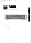
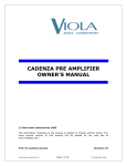
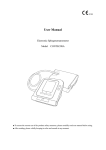
1.1.1 Universal Amplifier, Model 13-4615-58
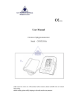
The performance of the Harvard Universal Amplifier, shown in Figure 1-1, truly lives up to its name universal. The unit acts as an excellent differential amplifier or provides the capabilities of a top grade
biophysical amplifier when utilized along with an Isolated Preamplifier, Model 11-5407-58. High input
impedance, wide bandwidth, low noise, low-drift and transducer excitation are all incorporated to produce the finest signal conditioning available in any single amplifier module.
U n i
v e r
s a l
full
sc
mv
cal
ale
zero pu
2.5
1
5
sh
.5
10
.25
push
25
.1
Off
.05
in
notch filt out
er
mv
x100
mv
ext
mv
Off
1v
calibra
te
cutoff
low
.1
.05
30
dc
offset
.3
10v
offset
fine
coarse
hz
high
1
3
M
10 30
100
10
300
30
100
1K
3K
10K
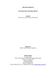
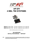
1.1.2 Isolated Preamplifier, Model 13-5407-58
Harvard’s Isolated Preamplifier, shown in Figure 1-2 enhances the performance of the Universal
Amplifier by providing signal isolation between the signal source and the measuring equipment. Since
the Isolated Preamplifier is intended to be physically placed near the signal source, the small biophysical signals are conditioned before they can be degraded by noise pickup or the capacitance of long signal cables. The Isolated Preamplifier was designed solely for use with the Universal Amplifier.
I s o l a t e d P r e a m p
A C
on
zero
D C
+
ref
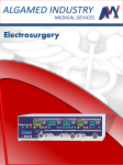
1.1.3 Defibrillator Protector, Model 11-5407-59
The Harvard Plug-in Defibrillator Protector is shown in Figure 1-3. This unit provides input protection for the Isolated Preamplifier when usage of a defibrillator or other stimulators in anticipated.
Defib Protector
1.2 Specifications
1.2.1 Model 13-4615-58
Amplifier Input:
Circuit Configuration:
DC
Differential and balanced to chassis
AC
Differential and balanced to chassis
Impedance:
“mv” and “mvX100” Range
Input Current
100 mΩ each input to chassis
< 100 pA either input at 25°C
Measurement Range:
“mVX100”
2.5 mV full scale to 10 V full scale
“mV” or “ext mV”
25 µV scale to 250 mV full scale
Attenuation
0.05, 0.1, 0.25, 0.5, 1, 2.5, 5, 10, 25,
full scale and OFF, “mV X100/mV/ext mV”
switch and “calibrate” vernier dial
Maximum Safe Voltage 120 V RMS; each input to common
Internal Calibration
DC Signal Source
mV, ext mV: Selectable between
50 µV an 1 mV with in ±1% at 25°C ±5 µV/°C
“mVX100”: Selectable between 5 mV and 100 mV
within ±1% at 25°C
Attenuator Inaccuracy
Non-linearity
Instability:
±0.5% of calibrated step
±0.1% of full scale
(after 30 minute warm-up)
DC Mode, 500 µV full scale:
Zero with Time
±4% of full scale/8 hrs
Zero with Line
±0.1% of full scale for a 10% line change
Zero with Temp
±2% of full scale/°C ±10%
Gain with Time
±0.02%/24 hrs
Gain with Line
±0.02 for ±10% line change
Gain with Temp
±0.03%/°C
AC Mode, 50 µV full scale (by design):
Zero with Time
±1% of full scale/24 hrs
Zero with Line
±0.4% of full scale for a 10% line change
Zero with Temp
±1% of full scale/°C
Gain with Time
±0.02%/24 hrs
Gain with Line
±0.02 for ±10% line change
Gain with Temp
±0.03%/°C
Frequency Response:
Low Cut Off
“DC offset”, “DC,” .05, .1, .3, 1, 3,
10, 30, 100 Hz, -3 dB, ±15%
of indicated frequency, -6 dB/oct
High Cut Off
0.05, 10, 30, 100, 300, 1000, 3000,
10,000 Hz -3 dB, ±15% of indicated
frequency, -6dB/oct
Notch Filter
60 Hz reject filter, minimum -20 dB
at 60 Hz, adjustable to 50 Hz
Noise (”mV” range, input shorted):
0.1 to 10 Hz
< 4 µV peak-to-peak, RTI
0.05 to 10 kHz
< 50 µV peak-to-peak, RTI
Common Mode Rejection
> 90 dB at 60 Hz with 1 kΩ imbalance
in “mV”. > 70 dB in “mVX100”
Calibrated Vernier
10 turn vernier to multiply setting
of attenuator or set transducer
calibration from 0.5 to 10.5X
Overload Recovery Time:
Low cutoff filter
AC
Manual via front panel “cal” switch
or external gate control
DC
10 msec compatible with time
constant
Offset Voltage (uncalibrated):
Range
Up to ±500 mV in “mV” range; up to
±10 V in “mVX100” range
Resolution
±2 µV in “mV” range; ±200 µV in
“mVX100 range
Stability:
After 30 minute warm up
With Time
±0.02%/24 hrs
With Temp
±0.05%°C
With Line
±0.02 for ±10% line change
Noise
±50 µV RTI on “mVX100” range;
± µV RTI on “mV” range
Excitation Voltage:
Range
5.0 V ±5 mV (±2.5 V nominal,
balanced to chassis)
Load Current
50 mA maximum (adjustable via
plug-in resistor)
Stability:
With Time
±0.05%/24 hrs
With Line
±0.02% for a ±10% change in line
With Temp
±0.05%/°C
Noise
0.1% P-P from DC to 1kHz
Power Requirements:
Voltage
±15 V, ±0.6 V, at 100 mZ
Line and Load Regulation 0.5%
Ripple
5 mV RMS maximum
Physical:
Exterior Dimensions, H x W x D (See Figure 1-4)
1.2.2 Catalog No. 60-0112
Amplifier Input:
Circuit Configuration
Differential and balanced to reference
Impedance
> 1000 mΩ shunted by < 30 pF in DC mode
(100 mΩ and 30 pF in AC mode)
Sink Rise Leakage Current < 10 µA at 230 V RMS, 60 Hz input to chassis
Noise (inputs shorted, “ext mV” only):
0.05 to 10 Hz
< 2 µ peak-to-peak RTI
0.05 to 10 kHz
< 12 µV peak-to-peak RTI
Input Current
< 100 pA at 25°C either input
Instability:
After 30 minute warm-up
Zero with Time
±4% of full scale/8 hrs
Zero with Line
±0.1% for a ±10% line change
Zero with Temp
±2% of full scale/°C
Gain with Time
±0.05%/24 hrs
Gain with Line
±0.05% for a ±10% line change
Gain with Temp
±0.05%/°C
Maximum Safe Voltage
50 V peak input to reference; 500 V
peak input to chassis
Maximum Common Mode:
Input to Chassis
100 dB at 60 Hz with 1kΩ resistive
inbalance
Input to Reference
80 dB at 60 Hz with 1 kΩ resistive
inbalance
Gain Accuracy
±0.3 of full scale
Linearity
±0.1% of full scale in 25 mV full
scale range; increasing to ±0.5%
in the 250 mV full scale range
Frequency Response:
(-3 dB)
Small Signal, 25 mV
InputAC: 0.016 Hz to 10 kHz
DC:
DC to 10 kHz
Full Power, 250 mV Input
AC: 0.016 Hz to 10 kHz ±10%
DC:
DC to 10 kHz ±10%
Amplifier Output:
Circuit Configuration
Single ended to common
Voltage
0 to 5 VDC linear range
Impendance
100Ω nominal short-circuit proof
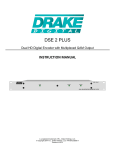
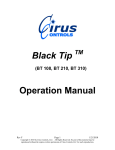
Physical:
Exterior Dimensions, H x W x D (See Figure 1-5)
6.1 x 8.1 x 18 cm (2.4 x 3.2 x 7 in)
(2.4 x 3.2 x 7 in)
3.2
INCHES
2.4
INCHES
7
INCHES
1.2.3 Catalog No. 60-0013 Defibrillator Protector
Impendance:
DC to 60 Hz
Between Inputs
> 10 mΩ with common mode signals
up to 2.5 V
Inputs to Chassis
> 50 mΩ each input to chassis
Leakage Current
The combined leakage of the
Defibrillator Protector and the
Isolated Preamplifier is < µA with
230 V RMS, 60 Hz applied
Defibrillator Protection
The circuitry is designed to withstand
up to 300 watt-seconds of defibrillator
pulse energy
1.3 SUPPLIES AND ACCESSORIES
Catalog No.
Product
60-0109
Input Mating Connector (Male)
60-0225
Three Lead Non-Isolated Patient Cable Kit
60-0129
Adapter Cable, Deutsch to BNC
60-0280
Isolated Physiologic Pressure Transducer
60-0281
Miniature Isolated Physiologic Pressure Transducer
60-0114
Isotonic Muscle Transducer
2.1 GENERAL
This section describes the checks and inspections that should be made upon receiving the
Harvard Universal Amplifier (Model 13-4615-58), Isolated Preamplifier (Model 11-5407-58) and
the Defibrillator Protector (Model 11-5407-59). Installation procedures and typical signal input
connections will also be discussed and diagrammed.
2.2 Initial Inspection
Prior to attempting any electrical connections or operation, visually examine the unit for broken
or loose knobs, dented or nicked panels and broken or chipped rear connectors.
2.3 Universal Amplifier Installation
The Universal Amplifier (Model 13-4615-58) may be mounted in any compatible Harvard
Recorder of 4600 Amplifier Series cage.
Caution:
Power must be turned off when installing or removing amplifier modules.
2.3.1 Insertion
To install the amplifier into its appropriate slot:
a.Slide the amplifier into the enclosure until the rear output card edge connector is engaged.
b.
Tighten the rear retaining screw until the amplifier front panel is flush with the edge of the enclosure.
DO NOT OVERTIGHTEN. This locks the preamplifier into the enclosure.
c.
The 12 pin Deutsch input cable connection at the rear of the amplifier module utilizes a locking ring
which snaps into place as a securing device. Install the input signal cable by aligning the blue line
on the locking ring on the cable connector with the polarizing key (See Figure 2-1) on the amplifier
connector. Push the cable connector in until the locking ring snaps into place and/or the orange ring
behind the locking ring on the connector shell becomes visible.
Caution: This type of connector (Deutsch) can be damaged beyond repair by attempting to twist or turn the locking ring. Do not
attempt to tighten this connector by screwing or turning the locking ring. Hearing the ring snap and/or observing the
orange ring behind the locking ring indicates total insertion has been attained.
2.3.2 Removal
a.
Disconnect the input connector by pulling back on the locking ring
b
Loosen the rear retaining screw. The preamplifier will move forward 1/8 of an inch
c.
Carefully slide the entire amplifier out of the enclosure.
2.4 Universal Amplifier Input Connections
This amplifier unit may be used as a general purpose AC or DC amplifier, as a transducer amplifier or as a biophysical signal conditioner. Table 2.1 gives a complete input pin and signal listing
and Table 2.2 indicates the connections for power and output signals available on the card edge
connector. The amplifier cage may have spade lug terminals or push on terminals depending
upon the model and manufacture date. Figure 2-2 gives a typical connector of the Universal
Amplifier as a general purpose amplifier while Figure 2-3 shows a schematic for a transducer
input. Use of Heart Sound Microphone (286700) and a Phone Jack/Deutsch Adapter Assembly
(11-5407-57) with a Universal Amplifier is shown schematically in Figure 2-4.
Polarizing Key
PIN
FUNCTION
1
2
3
4
5
6
7
8
9
10
11
12
NEC
NEC
NEC
NEC
NEC
(+) 15VDC
SHUNT CAL/(-) 15VDC
(-) EXC
(+) EXC
SHIELD
(+) SIG
(-) SIG
2.5 Isolated Preamplifier Installation
The Isolated Preamplifier (Model 11-5407-58) is a mobile unit which should be located as near
the patient as possible without exceeding the interconnect cable length of fifteen (15) feet. The
Deutsch connector on the Isolated Preamplifier cable is installed by aligning the blue line on the
locking ring on the cable connector with the polarizing key on the amplifier connector (See
Figure 2-1). Push the cable connector in until the locking ring snaps into place and/or the
orange ring behind the locking ring on the connector shell becomes visible. Note the caution in
Section 2.3 regarding the connector installation.
COMPONENT SIDE
PRINTED CIRCUIT SIDE
CARD EDGE
PIN NO.
1
2
3
4
5
6
7
8
A
B
C
D
E
F
H
J
SPADE LUG
TERMINALS
PUSH LUG
TERMINALS
9
1
8
6
3
13
12
11
10
1
2
3
4
5
6
5
7
8
9
10
11
12
FUNCTION
PWR COM
REC OUT
(-) 15VDC
(+) 15VDC
SIG COM
NEC
NEC
NEC
NEC
MON OUT
REMOTE RESET
RESET COM
NEC
NEC
NEC
SCALED OUT
DIFFERENTIAL MEASUREMENT
11
12
SOURCE
10
UNIVERSAL
AMPLIFIER
SINGLE-ENDED MEASUREMENT
11
12
SOURCE
10
TRANSDUCER
SHUNT CAL
RESISTOR*
SHUNT CAL
+E
7
(+) EXC
9
-S
+S
(-) SIG
12
(-) EXC
8
UNIVERSAL
AMPLIFIER
13-4615-58
(+) SIG
11
-E
SHIELD
10
*If a shunt calibration resistor is not installed
within the transducer or its connector, install
a jumper between pins 7 and 9 to allow installation of a shunt calibration resistor inside
amplifier module.
PHONE PLUG/DEUTSCH
ADAPTER ASSEMBLY
11-5407-57
HEART
SOUND
MICROPHONE
286700
PHONE
PLUG
11
12
10
(+) SIG
(-) SIG
SHIELD
11
12
10
UNIVERSAL
AMPLIFIER
13-4615-58
RA
ISOLATED
PREAMPLIFIER
LA
(+) 15VDC
6
(+)
(-) 15VDC
(-)
(+) SIG
7
12
REF
(-) SIG
11-5407-58
SHIELD
UNIVERSAL
AMPLIFIER
13-4615-58
11
10
RL
2.6 Isolated Preamplifier Connections
Figure 2.5 demonstrates the method of connecting the Isolated Preamplifier inputs to a patient
and outputs to a Universal Amplifier. Section 3.4.3 provide the instructions to insure the patient
hookup is performed safely and properly.
6
7
12
11
10
2.7 Defibrillator Protector Installation
The Defibrillator Protector is designed for mounting directly to the Isolated Preamplifier. Proper
installation is easily performed by following these steps:
1.
Disconnect the Isolated Preamplifier interconnect cable from the Universal Amplifier.
2.
Remove the front two cover screws from the Isolated Preamplifier
3.
Insert the three output pins of the Defibrillator Protector into the input jacks of the Isolated Preamplifier
4.
Align the mounting holes on the rear bracket of the Defibrillator Protector with the front two cover screw holes
on the Isolated Preamplifier
5.
Install the two screws to secure the Defibrillator Protector to the Isolated Preamplifier.
NOTE: These screws provide the ground connection for the Defibrillator Protector
and must be installed.
2.8 Defibrillator Protector Connection
Installation of the input connections to the patient must be performed in accordance with Section
3.4.3 Figure 2.6 shows the input/output configuration using the Defibrillator Protector, Isolated
Preamplifier, and the Universal Amplifier.
3.1 GENERAL
This section illustrates and describes the controls of the Universal Amplifier (Model 13-4615-58)
and Isolated Preamplifier (Model 11-5407-58). Complete operating instructions are also provided.
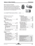
3.2 UNIVERSAL AMPLIFIER FRONT PANEL CONTROLS
Item numbers listed below refer to circled numbers in Figure 3-.
U n i v e r s a l
full scale
mv
cal
3
zero push
1
2.5
.5
5
10
10
.25
push
1
.1
25
.05
Off
in
8
out
notch filter
mv
x100
2
Off
10v
1v
mv
ext
mv
4
offset
fine
coarse
calibrate
5
9
cutoff
hz
low
.3
.1
6
high
10
1
M
3
30
100
.05
10
300
30
30
1K
dc
offset
3K
100
10K
7
ITEM
CONTROL
DESCRIPTION
1
full scale
The step sensitivity control selects recorder and monitors full-scale
outputs in millivolts and millivolts x100.
2
mvX100/mv/ext mv
The input signal encounters the internal 100 to 1 switch and then is
multiplied by the “full scale’ attenuator and the “calibrate” setting to obtain
the overall sensitivity of the amplifier. Maximum measurement range is
from 25 µV to 10 V full scale. The “ext mv” position is used for operating
with the optional Isolated Preamplifier.
3
mv bal
Amplifier DC zero shift balance control (see “zero-push”).
4
cal (momentary)
The switch selects either DC or bridge transducer shunt calibration resistor
(see Note 2). The “dc” position injects 1 mV or 100 mV 950 µV or 5 mV, internally
selectable) calibrate signal. The “dc’ position also overload restores the amplifier,
as well as defines the zero line when released.
5
offset (fine, coarse)
Concentric 10-turn controls for zero suppression or balancing bridge transducers
(see “cutoff”).
6-7
cutoff hz. (low, high)
The low and high switches select the bandpass of the amplifier for optimum
signal characterization. The ‘dc offset’ position balances bridge transducer or
provides zero suppression of unwanted DC signals. The “M” position limits the
amplifier response to 0.08 Hz or 2.0 seconds time constant for mean pressure
determination. (Time constant can be changed internally).
8
notch filter
The slide switch allows for 60 Hz noise rejection. The notch frequency can be
adjusted internally for 60 or 50 Hz.
9
calibrate
A dial vernier sensitivity control that provides overlapping ranges with stepless
adjustment from 0.5 to 10.5 times any setting of the “full scale” control
(times “mvX100/mv/ext mv” switch). The dial vernier is also used for the
calibration factor of strain gage transducers (See Note 1).
10
zero-push
This latching switch disconnects the signal source and shorts the amplifier inputs to
ground. This allows for rapid determination of the amplifier zero balance when the low
cutoff selector is in the “dc” position.
NOTE 1
Example: A typical blood pressure transducer has a calibration factor of 50 µV/V
excitation /10 mmHg. Multiplying 50 µV excitation times 5 volts times the full-scale
load pressure of 100 mmHg equals 2.5 mv at 100 mmHG. Therefore, if you dial 2.5
on the “calibrate” control, select “mv” and set the “full scale” to the “1`” position
you will have 100mmHg full scale or 1 decimeter Hg full scale). A shorter method
would be to divide the calibration factor by 20 and dial the number; for example:
50 - 20 = 2.5.
NOTE 2
Harvard Statham Blood Pressure Transducers purchased from Harvard Recording
Systems Division have shunt resistors installed equivalent to 100 mmHg (13.33 kilopascal).
3.3 UNIVERSAL AMPLIFIER USER CONTROLS
Item numbers listed below refer to Figure 3-2
E1, E2, E3, E8
Jacks for selecting (+) or (-) shunt calibration resistors. Jacks may be used to installed desired
calibration resistor is none supplied.
E4, E5
Jacks for setting excitation voltage to 5.0 V or 10.0 V
E6, E7
Jacks for setting mean output scale factor
S-2
Calibration Voltage selected at either 50 µV or 1 mV
S-3
Excitation Polarity Select – normal or reverse
J9
Provides direct output with cable assy. CL-612311 between TP-F and J9. Provides
mean output with shorting plug connector, 296520-1, on J9
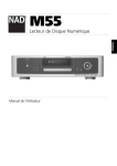
3.4 ISOLATED PREAMPLIFIER FRONT PANEL CONTROLS
Item numbers listed below refer to circled numbers in Figure 3-3.
ITEM
CONTROL
DESCRIPTION
1
AC/DC
This latching pushbutton selects AC or DC coupling of the Isolated Preamplifier. AC response is from
0.016 Hz (-3 dB). Best common mode is achieved in“dc” position
2
zero/on
This latching push button disconnects the input source signal and shorts the input to ground. In AC
mode, an overload can be restored by placing the switch in “zero” position
A C
D C
I s o l
a t e d
P r e a
m p
on
zero
+
ref
3.5 DESIGN FEATURE
The 13-4615-58 Universal Amplifier is designed to be three amplifiers in one. It operates extraordinarily
as a general all-purpose AC or DC Amplifier. It also accepts signals from pressure, force and strain gage
displacement transducers directly in units of measure. When used with the addition of the 11-5407-58
Isolated Preamplifier, it is capable of measuring high frequency nerve potentials as well as DC coupled
eye potentials, and nearly any other signal in the bioelectric field.
3.5.1 GENERAL PURPOSE
As an example, assume a positive DC input of 1mv maximum is to be fed into the Universal Amplifier
with the signal to be recorded on a chart recorder. The following setup procedures will prepare the system for operation:
1.
Install the amplifier module and connect the input cable
2.
Place “full scale” control to “off”
3.
Adjust “calibrate” dial vernier to 1.0 reading
4.
Select “dc” position on “low cutoff” switch
5.
Start recorder and adjust trace for chart center
6.
Set “mvX100/mv/ext mv” switch to “mv”
7.
Depress the “zero-push” switch to “zero”
8.
Place “full scale” control to “1”
9.
Release “zero-push” switch from “zero”
10.
Adjust trace to right chart edge
11.
Set “mvX100/mv/ext mv” seitch to “mvX100”
12.
Input 1 mVDC signal and pen should move to left chart edge.
(Refer to Section 2.4 for interconnection information. Accessories to assist in making
necessary circuit connections are listed in Section 1.3)
3.5.2.
DC BRIDGE AMPLIFIER
When utilizing a DC Bridge or transducer input, the following steps will balance the system for proper
operation:
1.
Install the amplifier module and connect the input cable
2.
Place “full scale” control to “off”
3.
Adjust “calibrate” dial vernier to 1.0 reading
4.
Select “dc” position on “low cutoff” switch
5.
Put “high cutoff” switch in “1k” position
6.
Start recorder and adjust trace for chart center
7.
Set “mvX100/mv/ext mv’ switch to “mv”
8.
Depress “zero-push” switch to “zero”
9.
Place “full scale” control to “1”
10.
Adjust “mv bal” potentiometer to center trace
11.
Select “10” position with “full scale” control
12.
Release “zero-push” switch from “zero”
13.
Place “low cutoff” switch to “dc offset” position
14.
Using the “coarse offset” and “fine offset” controls, position the trace to chart center
15.
While changing the “full scale” control to higher sensitivity positions, insure the
tracing remains at chart center by adjusting the offset controls. Now the amplifier
balance has been completed.
Four Transducers are sold through Harvard for the medical field:
P23ID Harvard-Statham Isolated Blood Pressure 369500-8916
P50 Harvard Statham Miniature Isolated Blood Pressure 369500-8904
UC2 Harvard Statham Bidirectional Isometric Force 369500-8640
Harvard Metripak Isotonic Muscle Transducer 793341-04042
UL5 Microscale Accessory for the UC2 Transducer 369500-8621
(Other transducers that use a 5 VDC excitation voltage and have outputs 25 µ V full
scale can be used)
3.5.3 WITH THE ISOLATED PREAMPLIFIER
A. Preliminary Set up
The following steps are used to balance the system prior to installing patient leads:
1. Install the Universal Amplifier and connect the Isolated Preamplifie interconnect
cable. (If the Isolated Preamplifier will be concurrently used with stimulators,
electrocauteries or defibrillators, insure a Defibrillator Protector is installed before the
balancing procedure is performed.)
2. Set the Universal Amplifier switches to these positions:
full scale
off
calibrate
1.0
low cutoff
dc
high cutoff
1k
3.
Start recorder and adjust trace to chart center
4.
Place “mvX100/mv/ext mv” to “mv”
5.
Depress “zero-push” button to “zero”
6.
Put “full scale” control to “10”
7.
Adjust “mv bal” potentiometer to position trace at chart center
8.
Release “zero/push”
9.
Place “mvX100/mv/ext mv” to “ext mv”
10.
Depress “zero-on” switch on Isolated Preamplifier to “zero”
11.
Check to insure the trace is at chart center. If not adjust “mv bal” to center trace
12.
Release “zero/on” switch to “on” position
13.
Input 5 mvDC into the Isolated Preamplifier. The pen should deflect to the left or
right side of the chart depending upon the signal polarity.
B. Patient Lead Connection
The following steps should be completed to protect against possible microshock
ards when placing patient leads.
haz-
1.
Depress “zero/on” switch on the Isolated Preamplifier to “zero” position
2.
Insure “mvX100/mv/ext mv” switch is in “ext mv”
3.
Only after all leads and/or electrodes are connected should any attempt be made to
monitor biophysical signals.
4.
Release “zero/on” switch to “on” position
5.
Before disconnecting or rearranging any leads or electrodes, depress the “zero/on”
switch to “zero” position on Isolated Preamplifier
SECTION IV
DESCRIPTION OF OPERATION
4.1 GENERAL
The Universal Amplifier (Model 13-4615-58) is a remarkable device because the high input impedance,
wide bandwidth, low noise and low drift capabilities. As evidence to its built-in versatility, the
Universal Amplifier can be used for general purpose AC or DC signal conditioning, measurement of
bioelectric phenomena, or strain gage transducer applications. This amplifier module can be combined
with the Isolated Preamplifier (Model 11-5407-58) and Defibrillator Protector (Model 11-5407-59) to perform high quality ECG or EEG monitoring without experiencing signal loss and noise while still being
protected against defibrillator damage.
4.2 UNIVERSAL AMPLIFIER (Model 13-4615-58)
This discussion will follow a block diagram (Figure 4-1) and will cover not only the basic function of
each block but also the unusual characteristics. Generally speaking, the direction of the presentation
will proceed along the normal signal (data) path with ancillary blocks covered as their functions come
into play.
4.2.1 INPUT SIGNALS (SHUNT CAL.)
Normally the (+)SIG and (-)SIG input signals are routed through the “zero-push” switch to the input
protectors. When the switch is depressed, the inputs to the amplifier is shorted to ground. These
shorted inputs are very useful when the user is calibrating the unit or wanting to identify the reference
or baseline.
Zero
On
On
Zero
REMOTE RESET
“cal” Switch
“coarse
offset”
“fine
offset”
(+) SIG
SHUNT CAL
(-) SIG
“zero-push”
Switch
E1
Offset
Amp
Input
Protectors
E2
E8
“low
cutoff”
Switch
“dc”
offset
Input
Amps
“mvX 100/
mv/
ext mv”
Switch
Reset
Circuit
Summing
Amp
Low
Cutoff
Filter
“low cutoff”
Switch
± 10 Volt
Reference
Reset
Relay
“cal”
Switch
Cal
Generator
+10V
-10V
Vernier
Gain
Amp
“calibrate”
vernier
Excitation
Drive
Generator
Notch
Filter
“out”
“in”
High
Cutoff
Filter
“mvX 100/
mv/
ext mv”
Switch
Scale
Select
Range
Amp
Scaled
Output
Amp
“full scale”
Switch
Located on
Chassis
Output
Driver
SCALED OUT
MON OUT
REC OUT
(-) EXC
(+) EXC
The SHUNT CAL input signal is activated during a transducer application when the “cal” switch is held in
the “shunt” position. A known value of resistance is connected across one arm of the transducer to provide a calibration voltage which offsets the amplifier’s output signal trace a prescribed amount.
Many medical transducers have a built-in shunt cal resistor and therefore a jumper must be installed
between E1 and E2 for a positive calibration input or from E1 to E8 if a negative calibration is desired.
(The jumper can be stored in E1 to E3 position if amplifier is not being used in a transducer application).
When no shunt cal resistor is built into the transducer, I.e. strain gages, the Deutsch input connector can
be jumpered between pins 7 and 9 to complete the SHUNT CAL signal path and a know value resistor is
then installed between E1 and E2 for positive calibration or E1 to E8 for negative calibration.
The Value of such a shunt cal resistor can be calculated using the following formula:
Rshunt =
1x10⁶
4NF
-
0.5 Ro
Where - 1.
N
= Desired calibration signal size
2.
F
= Calibraton factor provides on the Transducer’s certificate, i.e., uV/V/mmHg
3.
Ro
= the output resistance of transducer as found on the transducer’s certificate
Example:
N = 10 cmHg
F = 50 mV/V/cmHg
Ro = 300 ohms
4.2.2 INPUT PROTECTION
The Universal Amplifier is equipped with protection circuitry which will limit the input signal to the
input amplifiers. Back-to back diodes are placed on each input line to clip the signal level at ±15 volts.
This protection is capable of handling noise spikes or slight overvoltage signal but insufficient to prevent damage when a defibrillator is used. The maximum current specification for each of the diodes is
50 mA.
4.2.3 INPUT AMPS
The input amplifiers are basically voltage followers with a switch selectable gain possible. If the
“mvX100/mv/ext mv” switch is in the ”mvX100” or “ext mv” positions, the amplifiers have a unity gain.
The selections of “mv” on the switch inserts R3 and R7 into the circuitry and provides a gain of approximately twenty through the input amplifiers.
The ability to balance the output of the positive and negative input amps is provided through R18 and
R19. The “mvX100/mv/ext mv” switch selects the amount of common mode rejection to be inserted
into the positive amplifier”s output. When in “mv” position, R19 will supply proper compensation while
R18 is active in“mvX100” and “ext mv”. The common mode rejection (CMR) output is biased when the
“low cutoff” switch is placed in “dc offset” selection.
4.2.4 OFFSET AMPLIFIER
The offset circuit is designed to reduce or eliminate a DC voltage component of an incoming signal. If
the input signal varies between +5 mVDC and +10 mVDC, the area of interest does not include that
below +5 mVDC. By interjecting a -5 mVDC offset, the area of interest can be expanded to give greater
detail and a more useful output. The “fine offset” and “coarse offset” controls utilize the ±10 VDC reference output to supply the offset amplifier with its input. The offset amp provides the desired signal
correction through the CMR circuit when {dc offset” is selected on the “low cutoff” switch.
4.2.5 SUMMING AMP
The summing amplifier has the responsibility of combining the positive and negative input amplifier
output signals. Although the negative input amplifier has no alteration made to its output, the positive
input amplifier output will have common mode rejection correction inserted. This CMR signal can also
be biased by the offset amplifier when “dc offset” mode is selected on the “low cutoff” switch.
4.2.6 LOW CUTOFF FILTER
The “low cutoff” switch controls the function and limits of the low cutoff filter. When “dc” or “dc offset” is selected the filter is disabled and the summing amp output is resistively coupled to the next
stage. The remaining positions on the switch will provide capacitive coupling of the summing amp signal with -3 dB steps from .05 Hz and will establish the lower limit of the Universal Amplifier’s bandpass.
4.2.7 RESET CIRCUIT
The output from the low cutoff filter passes through a set of contacts on the reset relay. The reset circuit which drives this relay can be activated two ways – by remote reset or by depressing “cal” switch
to “dc”.
The remote reset signal places a ground on the input of the reset circuit which turns on the relay drive
transistor and charges a holding capacitor. Pulling in the relay causes the low cutoff filter output to
open and the ground potential to be sent through the “cal” switch to the vernier gain amplifier. In this
way, the amplifier can be reset and the zero baseline defined by a remote switch closure between cardedge pins C and D.
The second reset method is holding the “cal” switch in the “dc” position. The reset circuit will again be
activated by turning on the relay drive transistor and charging the holding capacitor. In this reset mode,
the “cal” switch applies the cal generator output to the vernier gain amp. Upon release of the “cal”
switch, the holding capacitor in the reset circuit keeps the reset relay energized for approximately 400
ms. Therefore, the output of the Universal Amplifier during a “dc” calibration sequence will be first at
the cal level, followed by a 400 ms zero (ground) baseline, and then a return to a normal input-following signal.
4.2.8 Cal Generator
The cal generator utilizes the + 10 VDC reference voltage to produce a known calibration voltage. An
internal switch, S2, permits selection of a 1 mV or 50µV output level. In addition two separate voltage
divider networks are used to generate the outputs required for calibration when the
“mvX100/mv/extmv” switch selects either “mv” or “mvX100” mode.
4.2.9 VERNIER GAIN AMP
The vernier gain amplifier is the only stage of the module which has the capability of the stepless front
panel gain control. The “calibrate” vernier can vary the gain of the universal amplifier form 0.5 to 10.5
times the “full scale” setting. This adjustment also allows the operator to calibrate the system when
used in a transducer application.
4.2.10 NOTCH FILTER
In some situations, a line frequency signal interferes with the true input and distorts the output beyond
acceptance. The notch filter is designed to minimize this problem by filtering out the line frequency
noise. The “notch filter” switch selects whether the filter circuit is used (“in”) or not (“out”). Internal
potentiometer R50 adjusts the center of the notch filter to either a 50 Hz or 60 Hz line frequency.
NOTE:
Universal Amplifiers that were built in early production lots used a 200 kΩ
potentiometer for R50 and there was an insufficient range of adjustment for50 Hz
applications. The new 500 kΩ pot allows adjust for both 60 Hz and 50 Hz line
frequencies.
4.2.11 HIGH CUTOFF FILTER
The rolloff frequency of the high cutoff filter is selected by the “high cutoff” switch and determines the
upper limit of the Universal Amplifier bandpass response. The “M” switch position provides a mean or
average output to the range amp and output driver. This “M” output is the same signal which is normally used by the scaled output amp.
4.2.12 SCALED MEAN OUTPUT AMP
The scaled mean output amplifier generates a continuous average output not affected by the “full scale”
or “high cutoff” switches. The “M” output form the high cutoff filter is conditioned to produce a ±10
VDC full scale output at card edge connector pin J. The gain of the scaled output amp is controlled by
R79 (scale select resistor) which plugs into E6 and E7. The amplifier is shipped with a 5 kΩ resistor
installed that give a scale factor of 10 but it can be replaced with other values to produce different full
scale factors. The following formulas will aid in selecting the correct resistor value for a specific application:
4.2.13 RANGE AMP.
The range amplifier receives its signal input from the high cutoff filter and control inputs from the
“mvX100/mv/ext mv” and “full scale” switches. The “mv” or “ext mv” selection boosts the amplifier gain
five times while “mvX100” does not request an increase in gain. The “mv” position also, provided a
gain of 20 in the input amp for a total of 100 times increase in sensitivity to this point while the
“mvX100” selection has maintained unity gain throughout. An “ext mv” input received unity gain in the
input amp and a five times increase in the range amp. To determine the overall system increase this far,
the 20 times boost in the Isolated Preamplifier must be figured and this brings the total to 100 times.
4.2.14 OUTPUT DRIVER
The output drive supplies the REC OUT and MON OUT signals for hard copy printing. The signals
from the range amp are received through an attenuator string which is switched by the “full scale” selections. This final stage then boosts the signal by a factor of 10 for sufficient output drive capabilities.
4.2.15 EXCITATION DRIVE GENERATION
The excitation drive generator utilizes the +10 VDC output of the ±10 volt reference to derive the excitation voltage for transducer applications. The standard excitation output signal are
± 2.5VDC with (+)EXC on card edge pin 9 and (-)EXC on pin 8. There is an internal switch (S3) which
provides a method of reversing the two outputs. If the transducer being used requires a different excitation voltage, R89 should be removed by unplugging the present resistor from E4 and E5 (see Figure 32) and replaced with another value of resistance. The following formula will determine the necessary
resistor in kΩ.
4.3 ISOLATED PREAMPLIFIER (Model 11-5407-58)
The purpose of the Harvard Isolated Preamplifier is to provide signal conditioning and amplification
near the signal source. this reduces the problem of noise and cable capacity effects on very high
impedance signal sources. The Isolated Preamplifier also provides electrical isolation between the signal
source and the measurement equipment. The preamplifier is intended for use with and powered by the
Harvard Universal Preamplifier.
4.3.1 INPUT CIRCUIT
The input signals, (+) and (-), may be AC or DC compled as selected on the AC/DC switch (see Figure
4-2). Once coupling is determined, the signals proceeds to the “zero/on” switch. When in the “zero”
position (depressed), the input lines are opened and all three leads are shorted together to produce a
zero base line. the “zero/on” switch should also be depressed during the connection of the input signal
source (See Section 3.4.3B).
4.3.2 INPUT PROTECTION
Back-to-back diodes are connected to each of the signal input lines to provide protection against excessive inputs up to 40 volts RMS. Once a input signal surpasses 15 volts, the clipping diodes will be
turned on and limit the signal strength.
4.3.3 INPUT AMP
The input amp consist of fully floating differential FET stages, a X20 gain amplifier for each signal and a
summing amplifier. The FET circuits provide low noise while the gain amplifiers permit balancing of
signals and adjustment of gain. After the signals are summed, the output of the input amp is sent to the
isolation amplifier.
ref
DC
AC
DC
AC
“AC/DC”
Switch
zero
on
zero
on
“zero/on”
Switch
INPUT
PROTECTION
ISOLATED
INPUT
AMP
ISO
ISO
+15VDC
-15VDC
ISOLATION
AMPLIFIER
(-) 15VDC
(+) 15VDC
SHIELD
(-) SIG
(+) SIG
NON-ISOLATED
4.3.4 ISOLATION AMPLIFIER
The purpose of the isolation amplifier is to provide electrical isolation between the input and output of
the Isolated Preamplifier. This is accomplished by modulating the input, passing it through a transformer and then demodulating the signal. This stage also isolates the (+) and
(-) 15VDC and common lines coming from the Universal Amplifier for usage in the isolated portion of
the preamplifier.
4.4 DEFIBRILLATOR PROTECTOR (Model 11-5407-59)
The Model 11-5407-59 Defibrillator Protector is designed specifically to protect the Model 11-5407-58
Isolated Preamplifier from defibrillator pulses with peak energy delivery up to 300 watt-sec.
The Defibrillator Protector reduces the high voltages in two stages. The first section consist of spark
gaps which short out any voltages above 1000 volts. The second stage has clamping transzorbs which
hold the maximum signal to 18.2 volts.