1
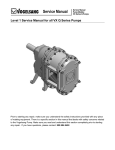
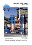
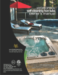
Service Manual
Service Manual
Pumps Models:
VX Series QD Pumps
Level 1 Service Manual for all VX QD Pumps
Prior to starting any repair, make sure you understand the safety instructions provided with any
piece of rotating equipment. There is a specific section in this manual that deals with safety
concerns related to the Vogelsang Pump. Make sure you read and understand this section
completely prior to starting any repair. If you have questions, please contact: 800.984.9400
Service Manual
Service Manual
Pumps Models:
VX Series QD Pumps
Depressurize QD Door & Buffer Chamber
IMPORTANT:
If your pump is equipped with a pressurized oil canister and you are working on the
mechanical seals in either the QD door or Gear Box end of the pump, you must
depressurize each chamber before you remove the seals.
Whenever the mechanical seals are removed from the pump, a pressure test is highly
recommended after re-installation of the mechanical seals and wet-end parts. This test
will confirm that installation has been successful and no o-rings have been cut or
pinched in the process. The pressurized oil bottle itself is ideal for this pressure test.
Pressure Testing:
1. Test for proper seal installation: Install a
pressurized oil bottle at the empty buffer
chamber port at the top of the pump. With the
provided hand pump or other air source,
pressurize the bottle (no oil in chamber) to
approximately 21 psi (1.5 bar) and observe the
gauge. Pressure should hold steady for at least
15 minutes. Then depressurize the bottle,
remove it, re-fill the buffer chamber and reinstall the pressurized oil bottle. A specific
pressure is to be set on the oil bottle which is
specific to your pump’s operating pressure.
Review the following page for instructions on
determining and setting the pressure for your
pump’s buffer chamber.
2. If the buffer chamber does not hold pressure it
will be necessary to disassemble and recheck
all o-rings for damage, and the lobe core
surfaces for proper preparation. Check also that
the seal cartridge is seated fully into the pump
body and the cartridge outer body is flush with
pump body.
3. Re-install pump outer door (front pump cover)
to complete assembly.
Use the included Hand Pump to
add pressure inside the empty
blocking chamber.
21psi equals about 1.5 bar on
your pressure gauge.
Service Manual
Service Manual
Pumps Models:
VX Series QD Pumps
Repressurizing Pump after completed maintenance
The pressurized buffer chamber canister (oil bottle) provides a constant pressure against the
mechanical seal helping to prevent infiltration of material from a higher pressure in the
pumping chamber. The semi-opaque container also allows easy monitoring of the oil level.
1. Fill the buffer chamber completely using the same oil as that used in the gearbox, ie.
80W90 hypoid gear oil.
2. If a non-pressurized oil bottle has been previously installed, remove and discard the bottle
and the check valve installed under the bottle. Install the pressurized oil bottle, screwing it
directly to the buffer chamber. On belt drive units, a hose kit is necessary to mount the
bottle in a remote location.
3. Fill the pressurized oil bottle about 1/4 full with buffer chamber oil (see above). Using the
supplied hand pump, pressurize the buffer chamber using the formula: 1/2 of normal
pump operating pressure plus 7 psi. For example, if your pump normally has a pressure
head on the suction side of 2 psi and a discharge pressure of 30 psi, the operating
pressure is 32 psi. Pressurize the oil bottle to (1/2 x 32) + 7 = 23 psi.
It’s as easy as a b c. Just fill in the blanks:
Step
Suction
Pressure
a
Discharge
Pressure
b
½ Differential
Pressure
Equals
Operating
Pressure
=
+
Operating
Pressure
c
Plus
Equals
Divided by
÷
2
=
Plus
PSI
Equals
+
7psi
=
½ Differential
Pressure
Gauge
Pressure
Service Manual
Service Manual
Pumps Models:
VX Series QD Pumps
Drain Pump Oil Reservoirs
NOTE: Depending on the type of
mechanical seal installed, the
pump may be supplied with a
pressurized oil bottle. In this
case, remove pressure and
unscrew oil bottle from the pump.
If the non-pressurized oil bottle is
used, remove the check valve
with the bottle.
Front Cover Drain
Fig. 1
Buffer Chamber Drain
Vogelsang QD pumps have three
oil reservoirs: Front Door, Buffer
Chamber and Rear Gear Box. All
chambers may use the same
Titan Gear MP90 mineral oil,
SAE90.
To begin service to the pump
wet-end drain oil from the QD
door (Fig. 1 Referred to as the
bearing housing in the parts list)
buffer chamber by loosening and
removing the bottom drain plug.
Remove the pressurized oil bottle
from the top of the chamber at
the same time. Place it in a safe
place for reuse.
Place a drain pan under the
pump to catch the quenching oil.
Remove the buffer chamber drain
bolt (Fig. 2) located on the
bottom of the pump. This part will
be reused.
Inspect the oil for foreign bodies
or other evidence of
contamination, as this may
indicate mechanical seal failure.
Gear Box Drain
Fig. 2
Remove the top bolt on the gear case of the pump, and save for re-use. Place an oil collection pan
under the pump, and loosen and remove the bottom drain plug from the gear case of the pump.
Inspect the oil for foreign bodies and other contaminants. This may be an indicator of mechanical seal
performance, or gear/bearing damage
Service Manual
Service Manual
Pumps Models:
VX Series QD Pumps
Removing QD Door including Mechanical Seals & Wearplate
Use a 19mm socket or wrench to
remove the 12 nuts around the
perimeter of the QD door (Fig 3).
Use the allen tool provided with
the Vogelsang lobe puller tool to
remove the strain screws (Fig. 4)
from the lobe shafts. Notice that
this tool is equipped with a
specially designed tip which acts
as a guide to hold the tool in
alignment in the bolt head. Use
of a standard metric allen wrench
may lead to “round out” issues in
the bolt head.
Retaining Nuts
QD Pump Door
Fig. 3
Fig. 4
Service Manual
Service Manual
Pumps Models:
VX Series QD Pumps
Remove two of the bolts for use
as jacking bolts to remove the
door (Fig. 5) from the wet-end of
the pump.
These bolts are used to pull the
sealed front door away from the
wet-end of the pump without
forcing or prying on it.
Screw one bolt into the top
threaded hole provided in the
cover. (Fig. 6)
Screw the second bolt into the
bottom threaded hole provided in
the lower end of cover. (Fig. 7)
Fig. 5
Fig. 6
Fig. 7
Service Manual
Fig. 8
Service Manual
Pumps Models:
VX Series QD Pumps
Alternating from top to bottom
bolt, tighten each bolt until the
door comes loose. The door will
be very heavy so be prepared to
support it as it comes out of the
wet-end housing segment. The
remaining perimeter bolts will
provide temporary support as the
door comes loose.
Fig. 9
Fig. 10
Pull the door away from the wetend of the pump. Make sure you
have a good grip on the door as it
is very heavy (Fig.10).
Note: If you are performing a
lobe change or are not working
on the door wear plate or door
side mechanical seals, you may
skip ahead to the next
appropriate section:
Removing Rotary Lobes: Fig 62
Fig. 11
Lay the door on a firm,
flat surface that supports
the weight of the door
(Fig 11).
Service Manual
Fig. 12
Service Manual
Pumps Models:
VX Series QD Pumps
Use external snap-ring pliers to
remove the retaining snap ring
(Fig 12 & 13) holding the o-ring
carrier in place.
Repeat process on other seal if
replacing or removing both.
Note: You do not need to remove
any part of the seal if you are just
replacing the wear plate. If this is
what you’re doing, then skip to
Fig 20.
Fig. 13
Fig. 14
Remove the o-ring (Fig 14). It is
easiest to use a pick to dig the
seals out of their track.
Note: You must replace ALL orings having to do with
mechanical seals.This o-ring
composition must match the
elastomer used in the pump.
Take care when ordering parts
that the full model number of the
pump is disclosed. All o-rings
come with the replacement
mechanical seal kit.
Service Manual
Fig. 15
Service Manual
Pumps Models:
VX Series QD Pumps
Use a flat tool similar to a
screwdriver or chisel to work the
carrier up and off of the sleeve
(Fig 15 & 16). Use a nut as a
fulcrum to make it easier to
loosen the carrier. Repeat this
procedure for top and bottom
shaft if removing second seal.
Any Nut
Fig. 16
Remove the o-ring and washer
(Fig 17 & 18)
Use an o-ring pick or similar
device to work the second o-ring
(Fig 19) from between the sleeve
and the cartridge seal.
Any Nut
Fig. 17
Fig. 18
o-ring will be deep in groove
Fig. 19
Service Manual
Pumps Models:
VX Series QD Pumps
Service Manual
Fig. 20
Use a 17mm socket or wrench to
remove the two bolts retaining
the wear plate to the bearing
housing (Fig 20 & 21).
It may be helpful to use a flat
screwdriver or similar device to
lift one edge of the inner wear
plate, then lift the plate free of the
gear housing.
Fig. 21
Remove retaining bolts
Fig. 22
Once the wear plate is loose,
(Fig 22) then simply remove the
plate by hand (Fig 23).
With the wear plate removed, the
mechanical seals are exposed
and can be removed (Fig 24).
Fig. 23
Fig. 23
Fig. 24
Service Manual
Pumps Models:
VX Series QD Pumps
Service Manual
Fig. 25
Use the Vogelsang seal
assembly tool to remove the
cartridge style seal assembly
from the bearing housing
(Fig 25).
Align the inner holes on the tool
with the threaded holes in the
mechanical seal stationary
housing (Fig 26).
Note: the threaded holes in the
mechanical seal stationary
housing may hold an allen-head
set screw designed to keep
material from building up in
the threaded hole and
damaging the fine threads.
Remove this set screw first,
using a 1.5mm allen
wrench.
Fig. 26
Fig. 27
Install the supplied mounting
screws to bolt the removal tool to
the stationary carrier housing.
Use a 5mm allen head wrench to
tighten the mounting bolts
(Fig 27 & 28).
You are attaching the removing
tool to the mechanical seal.
Fig. 28
Service Manual
Pumps Models:
VX Series QD Pumps
Service Manual
Fig. 29
Use the supplied long bolts to the
outer threaded holes of the
assembly tool. Hand tighten,
then, using a 10mm wrench, turn
each bolt 2-3 revolutions and
move on to the next, gradually
moving around the assembly tool
several times as the mechanical
seal assembly is lifted from the
bearing housing (Fig 29 & 30).
Note: It is possible for the seal
carrier to be very firmly
embedded in the bearing
housing. If necessary, use just
one turn per screw in a circular
fashion until the carrier
Fig. 30
begins to move. Attempting
to remove the carrier before
it is ready to move may
result in bending the tool
and rendering it useless.
Fig. 31
Lift the mechanical seal cartridge
and tool from the housing.
Remove the tool from the
cartridge assembly and repeat for
the remaining mechanical seal
(Fig 31).
Service Manual
Pumps Models:
VX Series QD Pumps
Service Manual
Fig. 32
With the cartridge assembly
removed, use an o-ring pick or
similar tool to pull the o-ring from
the cavity. If no further service to
the QD door is necessary,
proceed to the seal installation
section at this point.
Removing QD Door Bearings, Shaft Sleeves & Lobe Retainers
Fig. 33
To service the bearings and the
lobe retaining hardware, first flip
over the QD door. Use a 17mm
wrench to remove the four bolts
holding the bearing cover to the
housing (Fig 33).
Note: The two outside bolts are
longer than the two inside bolts
on each cover (Fig 34).
Remove 4 bolts
Fig. 34
Bolts are 2 lengths
Service Manual
Fig. 35
Service Manual
Pumps Models:
VX Series QD Pumps
Use a blade screwdriver or
similar tool to gently pry the cover
from the housing (Fig 35).
The cover will be filled with with a
lithium complex grease, NLGI
Grade 2, similar to the Chevron
product Ulti-Plex Greases EP.
However, any grease which
meets the NLGI Grade 2
classification will be suitable
(Fig 36).
Fig. 36
Fig. 37
Remove the pressure disk
and seal sleeve as a unit. Should
you need to replace one or the
other, disassemble the unit.
Otherwise, it may be removed
and replaced as a unit
(Fig 37 & 38).
Fig. 38
Service Manual
Fig. 39
Service Manual
Pumps Models:
VX Series QD Pumps
The spring washer (Fig 39),
although a separate part from the
pressure disk, snaps onto the
pressure disk assembly and does
not easily slip off the center
spool. If this assembly is
undamaged it may be reused.
To service the three pressure
disks, remove the spring clip
using a flat blade screwdriver or
similar tool to work the clip away
from its groove then lift and hold
with a second tool to remove.
Fig. 40
Note the position of the three
pressure disks (Fig 40) as they
are removed. Each is slightly
convex. Note that the convex
surfaces of the two inner spring
washers face each other, while
the concave surface of the outer
spring washer faces the concave
surface of the washer below it.
The position of the washers in
relation to each other is important
to maintain the tension designed
into the lobe retention system.
Fig. 41
Service Manual
Fig. 42
Service Manual
Pumps Models:
VX Series QD Pumps
Should service to the bearing or
bearing race be required, drive
the sleeve from the bearing
carefully with a plastic hammer
(Fig 42). The sleeve will be
removed as an assembly with the
bearing race (Fig 43) locking
sleeve and ring. Should service
to this assembly be required,
please refer to the bearing sleeve
assembly section.
Fig. 43
Fig. 44
If no service is
necessary, this part
does not have to be
removed.
To disassemble the shaft sleeve,
unscrew the angle ring (Fig 44).
Note: When reassembling, make
sure that the angle ring is
screwed in until it is properly
aligned with the surface of the
sleeve (Fig 45).
Fig. 45
Service Manual
Fig. 46
Service Manual
Pumps Models:
VX Series QD Pumps
Remove circle clip followed by
spring washers if not previously
removed. Then remove the dowel
from inside the sleeve
(Fig 46).
Note: When reassembling, the
dowel has to be inserted gently
into the sleeve. Do use a
hammer on the dowel.
The bearing (Fig 47) can be
removed once the sleeve
assembly has been driven out.
Use a stout hammer and drift to
remove the bearing.
Fig. 47
Service Manual
Service Manual
Pumps Models:
VX Series QD Pumps
Reassembling QD Door including Mechanical Seals & Wearplate
Fig. 48
Working in reverse. Start by
reassembling the bearings and
inserting shaft sleeves.
Reinstall the sleeve assembly in
the bearing using a hammer to
gently tap the sleeve into the
bearing on the bearing race. Do
not use excessive force. The
race should be well greased to
ease installation (Fig 48).
Fig. 49
Tap on outer ring only
Fig. 50
When reinstalling the
bearing cover ensure
the o-ring (Fig 49 ) is in
place. The o-ring may
be coated with grease
to hold it in place. The
use of oil or grease on
the o-rings during
installation is
encouraged.
Before installing cover, make
sure the pressure disk assembly
(Fig 50) is in place, and the
separate pressure disks have
been correctly installed.
Service Manual
Service Manual
Pumps Models:
VX Series QD Pumps
Fig. 51
Tap the cover into place taking
care that the o-ring seal is in
place and not pinched in the
cover (Fig 51). Do not overtorque the bolts. A snug fit is
sufficient (~40 ft. lbs.)
Fig. 52
Flip door over to begin
installation of mechanical
seals
Installation of the Blockring or
cartridge mechanical seal begins
with the installation of the inner oring (Fig 52). Note that this oring must be of compatible
material to the elastomer of the
lobes. Normally, this o-ring is
NBR as are the lobes. Should
your pump have non-standard
elastomers, this o-ring must
match that elastomer.
Service Manual
Fig. 53
Service Manual
Pumps Models:
VX Series QD Pumps
Oil the sleeve and the inner bore
of the mechanical seal and slide
the cartridge assembly over the
sleeve (Fig 53). Note that the oring (pos. 34) has been installed
on the body of the mechanical
seal cartridge (Fig 53).
Tap only (Fig 54) on the outer
stationary housing of the
mechanical seal cartridge. Be
careful not to hammer on the
inner rotating core of the
cartridge as this may damage the
mechanical seal. Tap gently
around the perimeter of the
cartridge to seat it all the way into
the bearing housing.
Fig. 54
Lay the o-ring (Fig 55) into place
around the perimeter of the
stationary housing of the
cartridge seal assembly. It is not
necessary to push this o-ring into
the groove formed between the
cartridge and bearing housing as
the o-ring will be seated properly
by the wear plate when it is
installed.
Tap on outer ring only
Fig. 55
Note: This o-ring must be
of compatible material to
the elastomer of the
lobes. Normally, this oring is NBR as are the
lobes. Should your pump
have non-standard
elastomers, this o-ring
and the one on the body
of the cartridge must
match that elastomer.
Service Manual
Fig. 55
Service Manual
Pumps Models:
VX Series QD Pumps
Install the door wear plate
(Fig 55). Ensure the wear plate
fits snugly against the bearing
housing indicating that the
mechanical seal is fully installed.
Install o-ring (Fig 56) around
bearing sleeve. This o-ring does
not have to be pushed into place
as the installation of the o-ring
carrier will fully seal the o-ring.
Over that, install the thin washer
and second o-ring.
Fig. 56
Don’t push into groove
Service Manual
Fig. 57
Service Manual
Pumps Models:
VX Series QD Pumps
Place the o-ring carrier (Fig 57)
over the end of the bearing
sleeve and push into place. Use
a plastic hammer to carefully seat
the carrier until the snap ring
groove is fully exposed (Fig 58).
Fig. 58
Use snap-ring pliers to seat the
snap ring (Fig 59) into its groove
above the o-ring carrier.
Tap on outer ring only
Fig. 59
Service Manual
Fig. 60
Service Manual
Pumps Models:
VX Series QD Pumps
Wet the o-ring (Fig 60) with oil
and seat in the groove provided
by the o-ring carrier just installed.
Before reinstalling the QD Door
be sure to install the sealing oring (Fig 61). If this o-ring is not
excessively compressed or cut it
may be reused.
Fig. 61
The door is now ready for
re-installation.
Sealing o-ring
Service Manual
Service Manual
Pumps Models:
VX Series QD Pumps
Removing Rotary Lobes
Fig. 62
Fig. 63
After the QD Door has been
removed and serviced, if
necessary, lobe change is
accomplished using the optional
lobe puller tool as illustrated
(Fig 62). Lobes must be pulled
out in pairs, top and bottom
together. Although this can be
accomplished using only one
lobe puller tool, the use of two in
tandem is recommended. Attach
the lobe puller arms into the ends
of the lobes, engaging machined
grooves. Tighten the arms with
the attached wing nuts and
steadily rotate the center screw of
the tool clockwise until the lobe
begins to move outward. Then
switch to the other tool and
repeat. Going back and forth
from tool to tool (or removing the
tool from one lobe and
connecting to the other, if only
one tool is being used), continue
until the lobes come loose from
the shafts.
Each lobe weighs approximately
30 lbs. so exercise care when
removing each from its shaft.
The lobes will be removed in
pairs, and one cannot be
removed without pulling its mate
simultaneously (Fig 63).
Service Manual
Fig. 64
Service Manual
Pumps Models:
VX Series QD Pumps
With the second set of lobes
exposed, remove the cover disk
around the core of each lobe
before attempting to attach the
lobe puller (Fig 64).
Remove the second set of lobes
in the same manner as the first,
pulling both top and bottom lobes
together until they slide off the
shaft (Fig 65). If your pump has a
third set of lobes, they are
removed in the same fashion.
Cover Disk
Fig. 65
Service Manual
Service Manual
Pumps Models:
VX Series QD Pumps
Removing Cartridge Mechanical Seal
Surface is free
of gouges or
elastomer
fragments.
Before continuing with
cartridge seal replacement:
Important! Once you’ve
removed the lobes, you must
evaluate the condition of the lobe
core that will contact the Block
Ring. Lobe condition is critical
to prevent premature seal failure.
Lobes provided before the
development of the Block Ring
seal may have partial coating on
the inner core which mates with
the seal. These lobes may show
small bits or pieces of the coating
in a jagged appearance around
the surface which is not
acceptable when using Block
Ring seals.
Surface has
even elastomer
coating with no
gouges.
New lobes have a smooth, clean,
machined appearance and show
no jagged bits of coating. If
lobes are being reused with the
Block Ring seal, attention must
be given to the condition of the
lobe core, assuring that it has not
been damaged.
Unacceptable: Jagged
pieces of coating on inner
core can lead to seal
failure.
Service Manual
Fig. 66
Service Manual
Pumps Models:
VX Series QD Pumps
With the aid of a hammer and
chisel, carefully tap the keys
(Fig 66) from their keyway, and
remove from the pump. Discard
the keys, as they cannot be used
again.
Remove any burrs from the shaft
with the aid of a file or emery
cloth. Take care not to injure
yourself on the sharp edges of
the keyway.
Fig. 67
Carefully reach into the pump,
and remove the wave washers
(Fig 67) from the shaft. If
replacing the cartridge or block
ring mechanical seal assembly,
these parts will be included and
should be replaced. If changing
just the lobes they may be
re-used, but replacement is
recommended.
Note: Washers (Fig 67) go on
top and bottom shaft. Re-install
them in the same location from
which they were removed.
Service Manual
Fig. 68
Service Manual
Pumps Models:
VX Series QD Pumps
Using a dental pick, o-ring puller
or similar sharp instrument,
remove and discard the o-ring
(Fig 68 & 69) located around the
pump shaft.
Note: Never re-use this o-ring.
Fig. 69
Service Manual
Fig. 70
Service Manual
Pumps Models:
VX Series QD Pumps
Loosen and remove the two bolts
(Fig 70) holding the rear wear
plate. Inspect the bolts for wear.
If in good condition, retain for reuse. If damaged, discard and
replace during re-assembly.
Remove wear plate. Inspect for
wear. If in good condition,
re-use. If damaged, replace. As
with the outer wear plate, some
wear is expected. Excessive
wear is determined by loss of
flow performance. When pump
flow is unsatisfactory the plate
must be replaced. This plate can
never be turned over for re-use.
Fig. 71
Note: The back wear plate has a
slight convex bend to it (Fig 71).
The plate is installed one-way
only, with the ends of the plate
pushing the center up slightly.
The retaining screws bring the
plate flush to the pump body and
provide tension to the assembly.
Service Manual
Fig. 72
Service Manual
Pumps Models:
VX Series QD Pumps
Remove the o-ring (Fig 72) at the
top of the mechanical seal
cartridge assembly. Discard the
o-ring and replace. This o-ring is
provided with the mechanical
seal assembly if the cartridge is
being replaced.
New cartridge and block-ring seal
assemblies are supplied with 2
small set screws on opposite
sides of the outer carrier of the
assembly. Remove these small
screws using a 2.5mm allen
wrench (Fig 73).
These set screws are installed to
help keep material out of the
threaded holes in the carrier used
by the cartridge removal tool.
Fig. 73
Special Tool Required
Service Manual
Fig. 74
Fig. 75
Service Manual
Pumps Models:
VX Series QD Pumps
Place the cartridge removal tool
ring over the shaft of one
cartridge assembly at a time.
Install two retaining screws to
attach the ring to the outer edge
of the carrier on the seal
assembly, and thread three
jacking screws into the removal
tool ring (Fig 74). As the jacking
screws are tightened into the ring
and against the pump housing,
the ring will pull the cartridge
assembly out of the seal bore.
Pull entire seal assembly up off
the lobe shaft. Repeat the
procedure for the other
mechanical seal assembly. Use
an even, slow pressure with the
jacking bolts to avoid bending the
assembly tool ring. Turn each
screw one or two turns at a time,
and rotate around the ring
increasing pressure with the
jacking screws (Fig 75).
Note: If re-using a mechanical
seal assembly, the o-ring around
the outer circumference of the
assembly must be replaced. This
o-ring is part of the seal assembly
kit when ordered new.
Service Manual
Fig. 76
Service Manual
Pumps Models:
VX Series QD Pumps
Remove the o-ring (Fig 75 ) from
the case. This is the same size
o-ring as the one on the outer
circumference of the seal
assembly.
Caution: The large o-rings used
with the mechanical seal
assembly are all the same size.
However, the o-ring used at
position 34 may be of different
material depending on the
elastomers used in the pump. All
elastomers are standard as NBR,
but optional elastomers may be
provided, if specified, to combat
reaction to specific chemicals
being pumped.
Note: This completes the
mechanical seal removal
procedure. The entire wet-end is
now disassembled. If you need to
work on the pump’s gearbox end,
skip to that section at this point.
Service Manual
Service Manual
Pumps Models:
VX Series QD Pumps
Installing Block Ring Mechanical Seals
Each Block Ring
Mechanical Seal Kit
Includes:
Block Ring Mechanical
Seal, 4 o-rings, flat
washer, pressurized
oil bottle and hand
pump. Do not
reuse your old parts.
Do not use
Non-pressurized
glass oil bottle
with Block Ring
Mechanical
Seals.
Pressurized plastic
oil bottle includes
hand pump
(included in kit)
Note: If you are
upgrading to our new
Block Ring mechanical
seal, you may have
our old style nonpressurized oil bottle.
All Block Ring seals
require a pressurized
oil bottle (included in
the kit), and the
pressure will depend
on your particular
application. Follow the
instructions in the Oil
Bottle InstructionsSG.Poilbottle.001 to
set the appropriate
pressure in the oil
bottle.
Service Manual
Surface is free
of gouges or
elastomer
fragments.
Service Manual
Pumps Models:
VX Series QD Pumps
Before continuing with
cartridge seal replacement:
Important! Once you’ve
removed the lobes, you must
evaluate the condition of the
lobe core that will contact the
Block Ring. Lobe condition is
critical to prevent premature
seal failure.
Lobes provided before the
development of the Block Ring
seal may have partial coating on
the inner core which mates with
the seal. These lobes may show
small bits or pieces of the
coating in a jagged appearance
around the surface which is not
acceptable when using Block
Ring seals.
Surface has
even elastomer
coating with no
gouges.
New lobes have a smooth,
clean, machined appearance
and show no jagged bits of
coating. If lobes are being
reused with the Block Ring seal,
attention must be given to the
condition of the lobe core,
assuring that it has not been
damaged.
Unacceptable: Jagged
pieces of coating on inner
core can lead to seal failure.
Service Manual
Service Manual
Pumps Models:
VX Series QD Pumps
Installing Block Rings
Seals:
Install the new o-ring around
the outer body of the new
mechanical seal cartridge,
liberally coating the o-ring
and the inside race of the
seal assembly with buffer
chamber oil (Fig 77), and
slide the cartridge seal and
seal removal tool (no bolts)
onto shaft and push into the
pump body as far as
possible by hand (Fig 78).
Fig. 77
Fig. 78
Lubricate the shaft and slide
in the lobe (without key in
keyway) against the removal
tool (Fig 79). Use the
existing pressure disks and
strain screw and draw the
lobe against the pump body,
thereby seating the
mechanical seal (Fig 80).
Remove the screw,
pressure disks, lobe and
removal tool.
Repeat this procedure on
the other shaft.
Fig. 79
Fig. 80
Service Manual
Service Manual
Pumps Models:
VX Series QD Pumps
Liberally coat seal outer o-ring
with buffer chamber oil, and set
o-ring in place. Do not attempt to
seat the o-ring between the seal
body and the pump body. This
will occur upon final assembly
and tightening of the lobes
(Fig 81).
Coat the smaller o-ring with oil,
and slide over shaft and against
the seal inner race. Take care
that the o-ring is not cut by the
sharp edges of the keyway
(Fig 82).
Fig. 81
Install the flat washer over the
shaft and against the o-ring
(Fig. 83).
Fig. 82
Fig. 83
Service Manual
Service Manual
Pumps Models:
VX Series QD Pumps
Place wear plate (Fig 84
pos. 37) into the pump,
insuring that the chromed
or ceramic side is facing
both you and the wet-end
of the pump.
Install the two screws
(Fig 85 pos. 38) that hold
the wear plate (pos. 37) in
place, and tighten
securely.
DO NOT USE AIR
TOOLS for this
operation. Hand tools
only.
Rotary Lobes are now
ready to be installed.
Fig. 84
Fig. 85
Service Manual
Service Manual
Pumps Models:
VX Series QD Pumps
Rotary Lobe Installation
Install a new key or keys
(Fig 86) into the shaft
keyway. Take care to
insure it is flush with the
front end of the shaft.
Fig. 86
Fig. 87
Inside Lip
With the aid of a brush,
lubricate the shaft, key,
and insides of the lobes
with hydraulic oil. Install
the lobes (Fig 87) taking
care that the inside lip is
facing you. Pumps
equipped with only two
lobes should have a left
lobe on the top, and right
lobe on the bottom shaft.
In the case of multiple
lobes, you alternate one
left, then one right lobe
per shaft, until all lobes
are installed. The reverse
is true on the other shaft.
The lobes should form a
“V”.
Service Manual
Service Manual
Pumps Models:
VX Series QD Pumps
QD Door is now ready to be
reinstalled (Fig 88).
Replace the O-ring (Fig 88).
Place the QD Door on the pump,
insure it is seated into it’s groove
(Fig 89).
O-Ring
Fig. 88
Fig. 89
Service Manual
Service Manual
Pumps Models:
VX Series QD Pumps
Securely tighten the twelve
retaining nuts (Fig 90).
Note: Old Strain Screws
CANNOT be re-used. Install only
new Strain Screws.
Lubricate the thread of the strain
screw with hydraulic oil, and
install by hand only until it cannot
be tightened any further by hand.
Repeat on other shaft.
Retaining Nuts
Fit lobe socket to torque wrench,
and torque each of the strain
screws (Fig 90) to the following:
Insert Strain Screws in
top & bottom shafts.
Torque Required:
VX186 Series = 147 f/lbs.
Fig. 90
Then loosen each strain screw
and re-torque each to 100 f/lbs.
Note: Review the section on
Adding Lubricants for instructions
about the proper method to refill
the pump buffer chamber and
gear box with the appropriate
lubricants.
Fig. 91
Service Manual
Service Manual
Pumps Models:
VX Series QD Pumps
Disassembly of Gearbox
To service the gear end
of the pump remove 10
M10x40 metric cap
screws around the
perimeter of the gear
case. Use an 8mm allen
wrench extended socket if
available. Inspect the
split lock washers and
replace if necessary. The
bolts may be re-used.
Note: If the shafts will be
removed, it is necessary
to remove the lobes and
mechanical seal
assemblies first. To
service the bearings or
gears, the shafts must be
removed.
With the aid of a hammer
and chisel, carefully tap
the key from its keyway,
and remove from the
pump. Discard the key,
as it will not be used
again.
Remove any burrs from
the shaft with the aid of a
file or emery cloth. Take
care not to injure yourself
on the sharp keyway
edges.
Service Manual
Service Manual
Pumps Models:
VX Series QD Pumps
Use a blunt drift in the
recesses provided
between the gear case
and the pump body.
Never hammer against
the feet of the pump. The
gear case uses four
dowels to position and
hold the case to the body.
It may require several
blows against the drift at
various points around to
loosen the case.
Once the cover has been
loosened, the use of a
chisel or similar tool can
aid in further removing
the case from the 4
dowels used to hold it in
place. Use care to loosen
the case evenly around
the pump body.
Service Manual
Service Manual
Pumps Models:
VX Series QD Pumps
Once loosened the case
can be lifted off the shafts
and put aside. Two
bearings reside in the
case, as well as the lip
seal for the outboard
shaft end and the cap
seal for the inboard shaft
opening. These will be
serviced later, if
necessary.
Special Tool Required
Service Manual
Service Manual
Pumps Models:
VX Series QD Pumps
Remove the case sealing
o-ring. Vogelsang
recommends replacing
this seal whenever the
case is removed, but if it
is undamaged and does
not indicate excessive
compression it may be
re-used.
Drive the two shafts from
the wet-end of pump
through the gear end of
pump. Use appropriate
drift and heavy hammer
as shaft is a tight fit
through the double roller
bearing.
Note: Provide soft
landing for the shafts as
they leave the pump
body, or use a helper to
hold shafts as they are
driven out of the pump.
Service Manual
Service Manual
Pumps Models:
VX Series QD Pumps
Pump body with shafts
removed.
Use a hammer and chisel
to bend the locking
washers away from the
retainer bolts. The bolts
may be re-used.
Service Manual
Service Manual
Pumps Models:
VX Series QD Pumps
Use a 17mm wrench to
remove the bolts around
the bearing retainers.
Discard the locking
washers and replace with
new.
Drive the roller bearings
from the pump body. Note
use of special tool to
avoid damaging the
bearing if it is to be
re-used.
Service Manual
Service Manual
Pumps Models:
VX Series QD Pumps
The bearing assembly
should emerge from the
pump body bore intact.
Thoroughly clean the
area with a fast-drying
solvent. We typically use
a good quality brake
cleaning product to
remove all traces of old
oil and grease.
Service Manual
Service Manual
Pumps Models:
VX Series QD Pumps
Reassembly of Gearbox
Apply liberal coats of oil to
all parts during reassembly of pump.
Drive bearing assembly
fully into the pump body
using an appropriate tool
to avoid damage to
bearing.
Service Manual
Service Manual
Pumps Models:
VX Series QD Pumps
The bearing housing
should be flush with the
pump housing when fully
seated.
Install bearing retainers
using new locking
washers. Bolts may be reused if undamaged.
Service Manual
Service Manual
Pumps Models:
VX Series QD Pumps
Use a hammer and chisel,
or similar tool, to bend
one edge of the locking
washer up against the
retainer bolt head.
Inspect assembly to
assure that no locking
washer edge extends
over the o-ring seat on the
corners, as this may
impede the re-assembly
of the gear case.
If it is necessary to
replace the shaft or gear it
will be necessary to build
an entire new shaft
assembly. Carefully
inspect the parts list for
correct parts for the shaft
being rebuilt.
First install the key for the
gear.
Service Manual
Service Manual
Pumps Models:
VX Series QD Pumps
Align the shaft key with
the gear keyway and
drive the shaft through
the gear until the key
aligns with the face of the
gear.
The shaft has been driven
through the gear and the
keyways are aligned.
Final position of gear is
created when spacers
and bearing race have
been installed.
Service Manual
Service Manual
Pumps Models:
VX Series QD Pumps
Install spacer on the
gearbox end of the shaft,
up against the gear face.
Then drive the bearing
race for the bearing over
the shaft and past the cut
groove in the shaft.
Install the circlip into the
groove to hold the
bearing race in place.
Install the bearing side
spacer. If the drive shaft
is being assembled, note
that a race must be
installed above the circlip
to accommodate the lip
seal installed later.
Service Manual
Service Manual
Pumps Models:
VX Series QD Pumps
When driving the shafts
back into the pump, take
care to properly orient
each shaft top to bottom.
Generally speaking, most
Vogelsang pumps are top
shaft driven, which puts
the idle shaft at the
bottom, closest to the feet
of the pump. Be sure to
verify the position of the
shafts when reassembling the pump.
Drive shaft into pump until
spacer is bottomed
against the double roller
bearing race and the gear
face.
Service Manual
Service Manual
Pumps Models:
VX Series QD Pumps
When installing the
second shaft, proper
timing of the gears must
be maintained by aligning
the single tooth marked
with an X on one gear
between the two teeth
marked with an X on the
second gear. Failure to
properly align the gear
teeth will render the pump
inoperable.
Second shaft installed
with gear teeth properly
aligned for correct timing.
Note: Gears are always
sold in sets as one part
number.
Service Manual
Service Manual
Pumps Models:
VX Series QD Pumps
To prepare the gear box
for re-assembly, remove
the retainer clip on the lip
seal for the outboard
shaft.
This clip fits snugly in the
machined groove just
above the lip seal.
Service Manual
Service Manual
Pumps Models:
VX Series QD Pumps
Pry the lip seal out of the
bore in the gear box.
Discard the seal; it will be
replaced in a later step.
If the case bearing (pos.
8) must be replaced, it will
have to be removed with
a blunt drift against the
bearing housing. The
bearing race must be
replaced on the outboard
shaft. See previous
instructions regarding the
rebuild of the shafts.
Service Manual
Service Manual
Pumps Models:
VX Series QD Pumps
The bearing is removed
through the inside of the
gearbox case. Note the
broken roller cage. This
is typical when attempting
to remove the bearing,
therefore remove this
bearing only when it will
be replaced with a new
part.
Remove the retaining clip
from the packing disk only
if you are replacing the
bearing, or if the packing
disk is leaking oil. This
part does not require
routine service.
Service Manual
Service Manual
Pumps Models:
VX Series QD Pumps
If the packing disk
\is to be removed drive it
out through the outside of
the gearbox case using a
suitable tool to avoid
bending the disk.
Replace the o-ring before
re-installing the packing
disk. Assure proper
seating of the o-ring in the
packing disk groove
before inserting back into
case.
Service Manual
Service Manual
Pumps Models:
VX Series QD Pumps
Seat the packing disk fully
into the bore until it
bottoms against the
casing. Use a suitable
tool to avoid damaging
the packing disk. Reinstall the retaining clip.
Place new lip seal in the
appropriate bore and seat
fully against the gearbox
casing. Re-install
retaining clip.
The gearbox housing is
now ready for
reassembly.
Service Manual
Service Manual
Pumps Models:
VX Series QD Pumps
Apply a thin coating of
lithium grease around the
seat for the o-ring and set
the o-ring in place. The
grease will keep the oring in place during
assembly. Be sure the oring is seated all the way
around the pump body.
Carefully replace the gear
housing to the pump.
Service Manual
Service Manual
Pumps Models:
VX Series QD Pumps
Re-install the drain plug
on the gearbox, taking
care to also re-install the
copper washer.
Note: Proceed to next
section regarding the
proper method to add
lubricants.
Service Manual
Service Manual
Pumps Models:
VX Series QD Pumps
Adding Lubricants
Double-check that all
drain plugs are installed in
the bottom of the pump.
Remove the side bolts
from the pumps gear box
From the top, fill the
gearbox with proper oil
until its begins to run out
of the side holes. Replace
the side drain plugs and
tighten. See lubrication
chart for appropriate oil.
Fill the blocking chamber
completely to the top with
the same oil used in the
gear box.
Note: Refer back to the
instructions regarding the
use of the Pressurized Oil
Bottle. The appropriate
pressure must be set to your
particular pump to help
ensure maximum
mechanical seal liftetime.