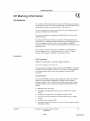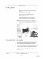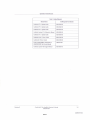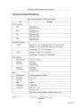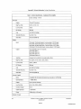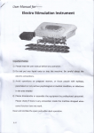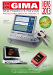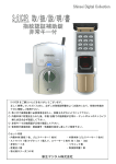
1
r II 2002938-001 Revision B Information Technologies gemedicalsyslems.com 000001 SJM03075096 ST. JUDE MEDICAL 1091 Trademarked names appear throughout this document. Rather than list the names and entities that own the trademarks or insert a trademark symbol with each mention of the trademarked name, the publisher states that it is using the names only for editorial purposes and to the benefit of the trademark owner with no intention of improperly using that trademark. 900 SC, ACCUSKETCH, AccuVision, APEX, AQUA-KNOT, ARCHIVIST, Autoseq, BABY MAC, C Qwik Connect, CardioLab, CardioServ, CardioSmart, CardioSys, CardioWindow, CASE, CD TELEMETRY, CENTRA, CHART GUARD, CINE 35, CORO, COROLAN, COROMETRICS, Corometrics Sensor Tip, CRG PLUS, DASH, Digistore, Digital DATAQ, E for M, EAGLE, Event-Link, FMS IDlB, FMS Ill, HELLIGE, IMAGE STORE, INTELLIMOTION, IQA, LASER SXP, MAC, MAC-LAB, MACTRODE, MARQUETTE, MARQUETTE MAC, MARQUETTE MEDICAL SYSTEMS, MARQUETTE UNITY NETWORK, MARS, MAX, MEDITEL, MEl, MEl in the circle logo, MEMOPORT, MEMOPORT C, MINISTORE, MINNOWS, Monarch 8000, MULTI-LINK, MULTISCRIPTOR, MUSE, MUSE CV, Neo-Trak, NEUROSCRIPT, OnlineABG, OXYMONITOR, Pres-R-Cuff, PRESSURE-SCRIBE, QMI, QS, Quantitative Medicine, Quantitative Sentinel, RAC RAMS, RSVP, SAM, SEER, SILVERTRACE, SOLAR, SOLARVIEW, Spectra 400, SpectraOverview, Spectra-Tel, ST GUARD, TRAM, TRAM-NET, TRAM-RAC, TRAMSCOPE, TRIM KNOB, Trimline, UNION STATION, UNITY logo, UNITY NETWORK, Vari-X, Vari-X Cardiomatic, VariCath, VARIDEX, VAS, and Vision Care Filter are trademarks of GE Marquette Medical Systems, Inc. registered in the United States Patent and Trademark Office. 12SL, 15SL, Access, AccuSpeak, ADVANTAGE, BAM, BODYTRODE, Cardiomatic, CardioSpeak, CardioQuick System, CD TELEMETRY®-LAN, CENTRALSCOPE, Corolation, EDIC, EK-Pro, Event-Link Cirrus, Event-Link Cumulus, EventLink Nimbus, HI-RES, ICMMS, IMAGE VAULT, IMPACT.wf, INTER-LEAD, IQA, LIFEWATCH, Managed Use, MARQUETTE PRISM, MARQUETTE® RESPONDER, MENTOR, MicroSmart, MMS, MRT, MUSE CardioWindow, NST PRO, NAUTILUS, 0zSENSOR, Octanet, OMRS, PHi-Res, Premium, Prism, QUIK CONNECT V, QUICK CONNECT, QT Guard, SMART-PAC, SMARTLOOK, Spiral Lok, Sweetheart, UNITY, Universal, Waterfall, and Walkrnom are trademarks of GE Marquette Medical Systems, Inc © GE Marquette Medical Systems, Inc., 2000. All rights reserved. T-2 CardioLab II Plus Amplifier Operator's Manual 2002938-001 000002 Revision B 15 June 2000 SJM03075097 Warranty Information term of the underlying Product Warranty. Scope of Wauanties Product Warranty: We warrant to you that all new cardiology Products made by us and sold by us or our authorized representatives (the "Warranted Products") will (I) be free from defects in title and in material and workmanship under normal use and service; and (2) except for Warranted Products manufactured in compliance with your designs or specifications, substantially comply with our technical written specifications on the date such Warranted Products are shipped to you (the "Product Specifications"). The Product Specifications are available upon request. Year 2000 Compliance Warranty: We warrant to you that tile Warranted Products are "Year 2000 Compliant" or will be made by us "Year 2000 Compliant" at no additional cost to you prior to the time when dates in 1999 or later could affect their operation. "Year 2000 Compliant" means that: (I) each Warranted Product will correctly accept, store, retrieve, compare, calculate, export, display, print out, sequence and otherwise process dates on, before and after January I, 2000, including leap years, in accordance witll the applicab~e Product Specifications; and (2) each Warranted Product s performance and functionality will not be materially adversely affected as a result of the date change from 1999 to 2000. Patent and Copyright Warranty: We warrant to you that when the Warranted Products are delivered to you, they will not be subject to any valid U.S. patent or copyright infringement claim. Warranty Limitations and Requirements The Product Warranty is limited in time, as follows: Prucka CardioLab® System: One year. Prucka Mac-Lab® System: One year. Prucka ComboLab System: One year. Ambulatory (Holter Recorders): One year. SEER® XT and SEER® MC: Two years. MARSTM Analog Remote System: One year. MARSTM Digital Remote System: One and one-half years. Defibrillators: One year. Resting ECG analysis and exercise testing systems (except batteries): One year. Resting ECG analysis and exercise testing system batteries: Ninety days. MAC 500 and MAC 1000: Three years. Cath Lab products: One year. The Year 2000 Compliance warranty extends through the 000003 The warranty period begins on the date the Warranted Products are delivered to you. If we assemble or install the Warranted Products, however, the warranty period begins on the earlier of (1) five days after the date we notify you that we have completed assembly or installation and the Warranted Products are operating in accordance the applicable Product Specifications, or (2) the date you first use Warranted Products for patient use. If assembly or installation is delayed for thirty days or more after the date of delivery for a reason beyond our reasonable control, the warranty period will begin on the thirtieth day after date of delivery, but under no circumstances will the warranty term begin later tIlan six months following the delivery date, regardless of cause. The warranty period for any Warranted Product or part furnished to you to correct a warranty failure will be the unexpired term of the warranty applicable to the repaired or replaced Product. W,rrranlly Exclusions These warranties do not cover: A. Any defect or deficiency (including failure to conform to Product Specifications) that in our reasonable determination results, in whole or in part, from (I) any alteration, improper storage, handling, use or maintenance, or any extraordinary. use of tile Products, by anyone other than us; (2) failure to maintain the Products in the manner described in any applicable instructions or specifications (including upper and lower date limits); (3) damage resulting from the use of electrodes, paper, batteries, magnetic media, patient sample line, filters, cuvettes, or other supplies not recommended by us; (4) using or combining the Products witll any item or data except as specified in the applicable Product Specifications or using or combining the Products witll any item or data that does not properly and unambiguously exchange data with the Products in accordance witll the applicable Product Specifications; (5) any of your designs, specifications or instructions; (6) any failure of any product to use or process correct dates, except as specified in the Year 2000 Compliance Warranty; and (7) any cause extemal to the Products as furnished by us or beyond our reasonable control. Our warranty only applies to Products purchased or supplied from us. Service repairs resulting from failures of equipment not purchased from us are billable at standard rates. SJM03075098 B. The payment or reimbursment of any facility costs arising from repair or replacement of the Warranted Products or parts. C. Any adjustment, such as alignment, calibration, or other normal preventative maintenance required of you. D. Expendable supply items, including without limitation electrodes, magnetic media, leadwires, patient cables, all external cabling on the Prucka CardioLab and Prucka Mac-Lab, ink, and ribbons. THE FOREGOING WARRANTIES ARE EXCLUSIVE AND IN LIEU OF ALL OTHER REPRESENTATIONS, WARRANTIES, AND COVENANTS, EXPRESS OR IMPLIED, WITH RESPECT TO THE PRODUCTS AND ANY DEFECTS THEREIN OF ANY NATURE WHATSOEVER. WE MAKE NO WARRANTIES RELATING TO MERCHANTABILITY OR FITNESS FOR A PARTICULAR PURPOSE OR USE. UNDER NO CIRCUMSTANCES SHALL WE BE LIABLE TO YOU UNDER ANY TORT, NEGLIGENCE, STRICT LIABILITY, OR PRODUCT LIABILITY CLAIM AND YOU AGREE TO WAIVE ANY SUCH CLAIMS. Exclusive Warranty Remedies Product Warranty and Year 2000 Compliance Warranty: Our sole responsibility for any breach of any warranty is, at our option, to repair or replace the Wan'anted Products or parts not conforming to the warranty, in accordance with any limitations listed above, provided that you promptly notify us of your warranty claim and make such Warranted Products available for service. Warranty service will be performed without charge from 8:00am to 5:00pm, Monday through Friday, excluding our holidays, and outside those hours and days at our prevailing service rates and subject to the availabili ty of personnel. thereof and cooperate with us with respect to such defense. If the infringement claim is determined by a court of competent jurisdiction to be valid, we will, at our option, also obtaln a license for you to continue using the infringing Warranted Product, provide a non-infringing replacement, alter the Warranted Product so that it is non-infringing, or remove the infringing Warranted Product and refund the price (less reasonable depreciation) and any return transportation costs paid by you. If we elect not to assume the defense, we shall also indemnify you for all expenses incurred in the defense of such infringement action. In like manner, you agree to indemnify and hold us harmless from claims of patent infringements relating to our compliance with your designs or specifications The above describes your exclusive remedies and our sole liability for any warranty claims. You agree that we and our representatives have no liability to you for (1) any penal, incidental or consequential damages, including without limitation, loss of business, goodwill, profit or revenue, (2) any assistance not reqUired under the Quotation, or (3) anything occurring after the warranty period ends. This exclusive remedy shall not have failed of its essential purpose (as that term is used in the Uniform Commercial Code) provided that we remain willing to repair or replace defective Warranted Products within a commercially reasonable time after receiving such Warranted Products. You specifically agree that our price for our Warranted Products is based upon the limitation of our liability as set forth in these terms and conditions. Warranty service for defibrillators and the MAC® PC resting ECG analysis systems will be provided on-site if the installation is located within 100 miles of any of our existing authorized service personnel, otherwise such Warranted Products must be returned to our factory. For return-tofactory warranty service, at your request, we will provide to you at no additional cost (except that you must pay all shipping charges) substantially similar temporary replacement Product until such warranty service is completed. Such temporary replacement Product will be loaned to you subject to these terms and conditions. Patent and Copyright Warranty: We shall indemnify you for all direct and actual damages recovered from you by a third person in any legal proceedings for infringement that would be a breach of the Patent and Copyright warranty, proVided that you promptly notify us in writing of the claimed infringement, permit us to assume full control of the defense 000004 SJM03075099 CE Information nee The CardioLab II Plus Amplifier bears CE mark CE-0459 indicating its conformity with the provisions of the Council Directive 93/42/EEC concerning medical devices and fulfills the essential requirements of Annex I of this directive. For devices manufactured in the United States, the CE mark is applied under the authority of Notified Body GMED (0459). The country of manufacture and appropriate Notified Body can be found on the equipment labeling. The safety and effectiveness of this device has been verified against previously distributed devices. Although all standards applicable to presently marketed devices may not be appropriate for prior devices (i.e. electromagnetic compatibility standards), this device will not impair the safe and effective use of those previously distributed devices. The CardioLab II meets the requirements ofEN60601-l-2 (1993-04) Medical Electrical Equipment, Part 1: General Requirements for Safety, 2. Collateral Standard: Electromagnetic compatibility - Requirements and tests. Exception IEC601-1-2 clause 36.202.1 - Immunit:'I: Radiated Immuniry The level of compliance is less than 1Vim If operating under the conditions defined in EMC Standard EN60601-1-2 (Radiated Immunity 3V1m), field strengths less than 1Vim may cause waYef9rm distortions and erroneous numeric data at various electromagnetic interference (EMI) frequencies. . Recommendations: Review the AAMI EMC Committee technical information report (TIR-18) titled Guidance on electromagnetic compatibility of medical devices for clinical I biomedical engineers - Part 1: Radiated radio-frequency electromagnetic energy. This TIR provides a means to evaluate and manage the EMI environment in the hospital. The following actions can be taken: Revision B l1li managing (increasing) distance between sources of EMI and susceptible devices II managing (removing) devices that are highly susceptible to EMI l1li lower power from internal EMI sources under hospital control (i.e. paging systems) III labeling devices susceptible to EMI III educating staff (nurses and doctors) to be aware of, and to recognize, potential EMI related problems CardioLab \I Plus Amplifier Operator's Manual 2002938-001 000005 CE-1 SJM03075100 CE Marking inrormation CE-2 CardioLab " Plus Amplifier Operator's Manual Revision B 2002938-001 000006 SJM03075101 Manual Information Revision History Manual Purpose Intended Audience Intended Use Chapter Content 1-3 1-3 1-3 1-3 1-3 1-4 Safety Information ... . . . . . . . . . . . . . . . . . . . . . . . . . . . . . . . . . . . . . . . . . . . . . . .. 1-5 Manufacturer Responsibility 1-5 General , , , .. , , , , .. 1-5 Equipment Symbols 1·1 Classilications Underwriters Laboratories Inc. (UL) Conventions. " Safety Messages, , .. , , , 1·8 1-8 , '" , .. , 1·9 1-9 , Danger, Warnings, and Cautions Service Information Service Requirements Equipment Identification 1·10 :, Equipment Overview , : . '.' . '" , .. '.' , , , .. , , , , , 1·13 1-13 1-14 . General Description. . . . . . . . . . . . . . . . . . . . . . . . . . . . . . . . . . . . . . . . . . . . . . . . .. 2·3 Cardiolab 1\ Plus Amplilier Hardware Amplifier Part Numbers Accessory Parts List . . . . . . . . . . . . . . . . . . . . . . . . . . . . . .. 2·4 2-4 2-4 Front View . . . . . . . . . . . . . . . . . . . . . . . . . . . . . . . . . . . . . . . . . . . . . . . . . . . . . . .. 2·5 Back View '" ...•................................ 2·1 Components. . . . . . . . . • . . . . . . . • • . . . . . . . . . . . . . . . . . . . . . . . . . . . . . . . . . . . .. CardioLab II Plus Catheter Input Module , Catheter Input Modules , Stimulator Input Cable , Revision B 2·1:\ 2-8 2-9 2-9 CardioLab II Plus Amplifier Operator's Manual 2002938-001 000007 SJM03075102 ECG 10 Lead Set 10 Lead ECG Cable Power Cord 2-9 2-10 2-10 Getting Started. . • . . . . . . . . . . . . . . . . . . . . • . . . . . . . . . . . . . . . . . . . . . . . . . . . . .. Connecting Cables to the Amplifier Disconnecting Cables From the Amplifier Installation Checkout 3-3 3-3 3-4 3-4 Related Manuals 3-11 Stimulator Bypass Connections for Emergency Pacing. . . . . . . . . . . . . . . . . . . . . . . . . . . . . . . . . . . . . . . . . . . . . . . . . .. 3-6 Move Connections 3-6 AppEmdix A = Mairltenj[lnce Overview . . . . . . . . . . . . . . . . . . . . . . . . . . . . . . . . . . . . . . . . . . . . . . . . . . . . . . . . . .. A-3 Maintenance/Repair Log A-3 Environmental Protection A-3 Inspection and Cleaning Precautions Cleaning Troubleshooting A-II A-4 A-4 ; : .....•..•.............................. A·S Storing and Transporting the Amplilier A·6 Maintenance/Repair log A·7 Appendix B-Technical Information Technical Specifications CardioLab II Plus Amplifier Operator's Manual . 8·3 Revision B 2002938-001 000008 SJM03075103 Manual Information Revision History Manual Purpose Intended Audience Intended Use Chapter Content , .. , .. , . , . , , , , , , , . , .. , , , , , , , .. , , , .. , , 1-3 1-3 1-3 , . 1-3 1-3 1-4 Safety Information ... . . . . . . . . . . . . . . . . . . . . . . . . . . . . . . . . . . . . . . . . . . . . . . .. 1-5 Manufacturer Responsibility , 1-5 General ,' , , 1-5 Equipment Symbols Classifications UnderwrITers Laboratories Inc. (UL) Conventions Safety Messages Warnings, and Cautions 1-1 . . . . . . . . . . . . . . . . . . . . . . . . . .. 1·8 1-B " , " 1-9 1-9 1·10 Service Information. . . . . . . . . . . . . . . . . . . . . . . . . . . . . . . . . . . . . . . . . . . . . . . .. 1·13 Service Requirements .. , , 1-13 Equipment Identification , , , , 1-14 Revision B CardioLab II Plus Amplifier Operator's Manual 1-1 2002938-001 000009 SJM03075104 For your notes 1-2 CardioLab II Plus Amplifier Operator's Manual 2002938-001 000010 Revision B SJM03075105 Introduction: Manual Information I !1iI"ll'll'_1I"1!'Yll Each page of the document has the document part number and revision letter at the bottom of the page. The revision letter identifies the document's update level. The revision histOIY of this document is summarized in the table below. Table 1. Revision History PN 2002938·001 B I November 15, 2000 I Release Bof this manual. This manual contains the instructions necessary to operate the CardioLab II Plus Amplifier safely in accordance with its function and intended use. These instructions include but are not limited to: III a fundamental description of controls and indicators, iii operating procedures, and III connection and disconnection of detachable parts and accessories. Where necessary the manual identifies additional sources of relevant information and/or technical assistance. This manual is intended for the person who uses, maintains, and/or troubleshoots this equipment. . The CardioLab II Plus Amplifier is intended for use in an electrophysiological catheter laboratory or catheterization laboratory where ECG, direct cardiac, intracardiac and pressure signals need to be recorded from a patient. This device is intended for use under the direct supervision of a licensed health care practitioner. Revision B CardioLab \I Plus Amplifier Operator's Manual 1-3 2002938·001 000011 SJM03075106 Introduction: Manual Information This manual is organized into the following chapters: 1 Describes the manual contents and provides general information about safety precautions, service requirements, equipment symbols and serial number identification. 2 Equipment n"'''''.... 'i'''''Ul' Gives a description of the equipment and components. 3 Operation Describes how to connect and disconnect cables to the amplifier and provides a list of related user's manuals and update gUides. Describes the stimulator bypass connections for emergency pacing. Appelndix A: Maintenance Troubleshooting Describes how to maintain the equipment and keep it in good working order with a recommended maintenance schedule, cleaning guidelines, checkout procedure, and safety tests. Provides a complete table of technical specifications for the CardioLab II Plus Amplifier. 1-4 CardiaLab " Plus Amplifier Operator's Manual 2002938-001 000012 Revision B SJM03075107 Irrtrodl.lction: Information Please read all of these instructions carefully. Follow all of the instructions and warnings marked on this product or included in this manual. Save these instructions for later use. GE Marquette Medical Systems is responsible for the effects of safety, reliability, and performance only if: 11II Installation operations, extensions, readjustments, modifications, or repairs are carried out by persons authorized by GE Marquette. III The equipment is used in accordance with the instructions for use. III The user attaches only accessory equipment recommended for interaction with the amplifier. The CardioLab II Plus Amplifier maintains leakage currents below medical limits with an isolation transformer, which is incorporated into the design of the amplifier. Amplifier power should be supplied by a dedicated power supply on an isolated circuit for proper behavior of the amplifier. To ensure patient safety, use only parts and accessories manufactured or recommended by GE Marquette Medical Systems. This equipment should only be connected as specified by GE Marquette Medical systems. Installation of the equipment should only be performed by qualified GE Marquette Medical Systems service representatives. Contact GE Marquette Medical Systems before connecting any.device to equipment that is not recommended in this manual. Only cables and accessory equipment purchased from GE Marquette Medical Systems should be used in conjunction with the amplifier. It is important that all of the instructions in this manual be followed, however, these instructions in no way supersede current medical practices regarding patient care and safety. Parts and accessories used must meet the requirements of the applicable IEC 60 I series safety standards, and/or the system configuration must meet the requirements of the IEC 601-1-1 medical electrical systems standard. Refer servicing of amplifiers under warranty to GE Marquette Medical Systems authorized service personnel. Any attempt to repair equipment under warranty will void that warranty. It is the responsibility of users of systems needing service to contact GE Marquette Medical Systems for servicing of the equipment. Failure on the part of responsible individuals or institutions to implement a satisfactory equipment maintenance schedule may lead to undue equipment failure and possible health hazards. Revision B CardioLab II Plus Amplifier Operator's Manual 1-5 2002938-001 000013 SJM03075108 Introduction: Safety Information The use of ACCESSORY equipment not complying with the equivalent safety requirements of this .equipment may lead to a reduced level of safety of the resulting system. Consideration relating to the choice shall include: III use of the accessory in the PATlENT VICINITY; and II evidence that the safety certification of the ACCESSORY has been performed in accordance to the appropriate lEC 601-1 and/or lEC 601-1-1 harmonized national standard. The CardioLab II Plus Amplifier is a component/accessory of a Class II medical device. 1-6 CardioLab II Plus Amplifier Operator's Manual Revision B 200293B-001 000014 SJM03075109 Introduction: Equipment Symbols The following symbols appear Oll the equipment. Attention ~ p" "",hoo 10 th, ',,"moo" ",;,,"', w," th' ",";pmo", Type CF Equipment Type CF equipment is specifically designed for applications where a conductive connection to the heart is directly established. Type Cf Equipment ~ Type CF equipment that is defibrillator proof. Isolated (floating) applied part suitable for intentional external and intemal application to the patient including direct cardiac application. "Paddles" outside the box indicate the applied part is defibrillator proof. [Medical Standard Definition:] F-type applied part (floating/isolated) complying with the specified requirements of IEC 60601-1/UL 2601-1/CSA 601.1. Medical Standards to provide a higher degree of protection against electric shock than that provided by BF applied parts. Equipotentialiiy A nonessential electrical connection which may be used to connect the chassis to other equipment to achieve the same potential. PO 1000-001. -002. -003. -004. -005 Revision B CardioLab II Plus Amplifier Operator's Manual 2002938-001 000015 1-7 SJM03075110 Introduction: Classifications The CardioLab II Plus Amplifier is classified, according to lEC-60601-1, as: Type of protection against electrical shock I Degree of protection against electrical shock CF-ECG, BP, elM, Auxiliary Inputs Degree of protection against harmful ingress of water Ordinary Degree of safety of application in the presence of a Not suitable flammable anesthetic mixture with air or with oxygen or nitrous oxide Method(s) of sterilization or disinfection recommended by the manufacturer Not Applicable Mode of operation Continuous operation I: Class] equipment CF: Type CF applied part Ordirlary: Ordinary equipment (enclosed equipment without protection against ingress of water) Not Suitable: Equipment not suitable for use in the presence of a flammable anesthetic mixture with air or with oxygen or nitrous oxide Inc. ( Underwriters laboratories, inc. C 1-8 Classified by Underwriters Laboratories Inc. with respect to electric shock, fire, mechanical US and other specified hazards, only in accordance with UL 2601-1, CAN/CSA C22.2 No. 601.1, IEC 60601-1, and, if required, IEC 60601-2-27, IEC 60601-2-30, IEC 60601-2-34, IEC 60601-1-1. CardioLab II Plus Amplifier Operator's Manual Revision B 2002938-001 000016 SJM03075111 Introduction: Conventions These are the conventions used in this manual. DANGER safety messages indicate an imminently hazardous situation which, if not avoided, WILL result in death or serious injury. WARNING safety messages indicate a potentially hazardous situation which, if not avoided, COULD result in death or serious injury. CAUTION safety messages indicate a potentially hazardous situation which, if not avoided may result in minor or moderate injury. NOTE messages provide additional user information. Revision B CardioLab II Plus Amplifier Operator's Manual 2002938-001 000017 1-9 SJM03075112 Introduction: Danger, Warnings, and Cautions DANGlER EXPLOSION HAZARD Do not use in the presence of flammable anesthetics or other flammable gases. WARNINGS ACCESSORIES Only connect to UL 544 or UL 2601-1 listed or IEC certified medical equipment. Use only Catheter Input Module (CIM) #301-00202-08 or #30100203-08 with the CardioLab II Plus Amplifier. All equipment not complying with IEC 601-1 should be placed outside the patient environment. ACCIDENTAL SPILLS If fluid of any kind should leak into the CardioLab II Plus Amplifier, discontinue using the amplifier and contact GE Marquette Medical Systems. DO NOT allow hydraulic fluid from any device to contact any conductive surface. Hydraulic fluid is electrically conductive. Do not allow any foreign materials such as fluids to corne in contact with the CardioLab II Plus Amplifier. . BACKUP MONITORS Back-up patient monitors should always be available while using CardioLab II Plus Amplifiers. CONDUCTIVE CONNECTIONS Proper connections to the patient are critical for the proper operation of the CardioLab II Plus Amplifier and patient safety. Use extreme caution when making patient connections. Do NOT connect non-isolated equipment to the amplifier. Proper connections to the stimulator are critical for the proper operation of the CardioLab II Plus Amplifier and patient safety. Use extreme caution when making stimulator connections. The stimulator must be a IEC 601-1 certified product. Ablation operations should NOT be executed when a stimulator unit is connected. 1-10 CardioLab II Plus Amplifier Operator's Manual 2002938-001 000018 Revision B SJM03075113 Introduction: Danger, Warnings, and Cautions Keep the conductive parts of lead electrodes and associated parts away from other conducting parts, including earth ground. DEFIBRILLATOR PRECAUTIONS Standby defibrillation equipment is required in the event that the patient needs to be cardioverted or defibrillated. Do NOT come in contact with the unit or patient during defibrillation. LEAKAGE CURRENT TEST When more than two electrical devices are interconnected, the summation of leakage currents must be checked before use and rechecked yearly. Keep leakage current within acceptable limits when connecting auxiliary equipment to this device. Total system earth leakage current must not exceed 50 microamperes. MAINTENANCE Check the electrical integrity of the signal connections in the catheter input modules and cabling yearly. Replace only with the same type and rating of fuse. POWER SUPPLY To reduce the risk of electric shock or damage to your equipment, do not disable the power cord grounding feature. This equipment is designed for connection to a grounded (earthed) power outlet. The grounding plug is an important safety feature. . Electrostatic discharge (ESD) 'can damage electronic components. Be sure you are properly grounded when using the CardioLab II Plus Amplifier. Connect only to a properly earth grounded outlet. SUPERVISED USE This device is intended for use under the direct supervision of a licensed health care practitioner. Revision B CardioLab II Plus Amplifier Operator's Manual 1-11 2002938-001 000019 SJM03075114 Introduction: Danger, Warnings, and Cautions CAUTIONS Caution: Federal (USA) law restricts this device to sale by or on the order of a physician. ACCURACY Erroneous values may occur if unused catheter inputs are not properly connected. DO NOT display any channels which are based on unused catheter input modules. Otherwise erroneous values may occur. CABLES Route optical cables though a conduit in the ceiling or floor to avoid damage to the cables or cable connectors. DEFIBRILLATOR PRECAUTIONS ECG inputs are protected against the use of a defibrillator in conjunction with the use of the ECG cable. The pressure inputs on the CardiaLab II Plus Amplifier are protected against the use of a defibrillator in conjunction with the use of the recommended pressure trandsucer and reusable cable. MAINTENANCE Remove air that is trapped in the transducer or associated tubing by flushing the system according to cath lab procedures. To reduce the risk of electric shock, DO NOT remove cover (or back). Refer servicing to qualified personnel. This equipment contains no user serviceable parts. Refer servicing to qualified service personnel. . . POWER SUPPLY The CardioLab II Plus Amplifier may be safely powered by line voltages of 100-240 VAC with frequencies of 50-60 Hz. 1-12 CardioLab II Plus Amplifier Operator's Manual Revision B 2002938-001 000020 SJM03075115 Introduction: Service Information Follow the service requirements listed below: Revision B l1li Refer equipment servicing to GE Marquette Medical Systems authorized service personnel only. l1li Any unauthorized attempt to repair equipment under warranty voids that warranty. l1li It is the user's responsibility to report the need for service to GE Marquette Medical Systems or to one of their authorized agents. IIiI Failure on the part of the responsible individual. hospital. or institution using this equipment to implement a satisfactory maintenance schedule may cause undue equipment failure and possible health hazards. l1li Regular maintenance, irrespective of usage, is essential to ensure that the CardioLab II Plus Amplifier will always be functional when required CardioLab II Plus Amplifier Operator's Manual 1-13 2002938-001 000021 SJM03075116 Introduction: Service Information Every GE Marquette Medical Systems device has a unique selial number for identification. The serial number appears on the back of the CardioLab II Plus Amplifier. CLAB II Plus Amplifier Bar Code Table 1. Equipment Identifications Item Description Name A manufacturer GE Marquette Medical Systems, Inc. B name of device CLAB II Plus Amplifier C serial number Unique identifier D month manufactured A = January, B = February, C = March, D = April, E = May, F = June, G = July, H = August, J = September, K = October, L = November, M = December E year manufactured 9 = 1999,0= 2000, 1= 2001, (and so on) F product code Two-character product descriptor XJ= CLAB II Plus Amplifier G product sequence number Four-character manufacturing number (of total units manufactured) H plant designator F = Cardiology I device characteristics One or two characters that further describe the unit, for example: P = prototype not conforming to marketing specification; R = refurbished equipment; S = special product documented under Specials part numbers; U = upgraded unit 1-14 G = Monitoring CardioLab II Plus Amplifier Operator's Manual 2002938-001 000022 Revision B SJM03075i 17 I t " General Dmicrilptioln . . . . . . . • . . • • • •• • • . . . . . . . . . . . . . . . . . . . . . . . . . . . . . . . .• 2-3 Cardiolab II Plus Amplifier Hardware ..... . . . . . . . . . . . . . . . . . . . . . . . . . . . . .. 2-4 Amplifier Part Numbers " " " " " " " " " " , , , , . , , , . , , , , , , , , , , , , , , , , 2-4 Accessory Parts List """".""".,.",."".,.""""""",.,.2-4 Front View. . . . . . . . . . . . . . . . . . . . . . . . . . . . . . . . . . . . . . . . . . . . . . . . . . . . . . . . .. 2-5 BackView 2-7 Components. . . . . . . . . . . . . . . . . . . . . . . . . . . . . . . . . . . . . . . . . . . . . . . . . . . . . . .. 2-8 CardioLab II Plus Catheter Input Module ,.,,,,. , , , , . , , .2-8 Catheter Input Modules .,., , "., ,., . , . , , . , . , . , . , . 2-9 Stimulator Input Cable. , .. , ,,., ,, , .. , . , , . , . , .2-9 ECG 10 Lead Set, . , , ,, , , .. , , , , , .. , , ,2-9 10 Lead ECG Cable. , , . , , , ,, , ,. , 2-10 Power Cord. , . , , .. , ,., , ,. ,,., 2-10 Revision B CardioLab II Plus Amplifier Operator's Manual 2002938-001 000023 2-1 SJM03075118 For your notes 2-2 CardioLab II Plus Amplifier Operator's Manual Revision B 2002938-001 000024 SJM03075119 Equipment Overview: General Description The CardioLab II Plus Amplifier is designed to amplify various types of cardiac signals that are acquired from a patient and transmit them back to the Prucka CardioLab/Mac-Lab system, referred to in this manual as the acquisition computer. These signals include 12 Lead ECG, intra-cardiac and pressure signals. The CardioLab II Plus Amplifier is fully supported by CardioLab EP software versions 3.1 and above and CardioLab Cath software versions 1.0 and above. However, the CardioLab II Plus Amplifier was designed specifically for use with the Prucka CardioLab/Mac-Lab system. The following table lists the functionality of the CardioLab II Plus Amplifier with the different software versions. Table 1. Cardiolab II Plus Functionality for Different Versions of Cardiolab Software Cardiolab II Plus Functionality Cardiolab EP 3.1 and Above/Cardiolab Cath 1.0 and Above Prucka CardiolablMac·lab System Intracardiac Blocks A and B Only All Blocks Available Stimulator CardioLab II Amplifier Equivalent Enhanced SWitching Options Auxiliary Input Not Available RF Filtered and Unipolar Inputs The CardioLab II Plus Amplifier supports 32,64,96 and 128 channel configurations. The following list illustrates the number of Catheter Input Modules (CIM) used with the four configurations of the CardioLab II Plus Amplifier: .. 32 Channels: 1 CIM .. 64 Channels: 3 CIMs .. 96 Channels: 5 CIMs .. 128 Channels: 7 CIMs The Catheter Input Modules for the four configurations of the CardioLab II Plus Amplifier connect to the following catheter inputs on the front of the amplifier: Revision B .. 32 Channels: Input A .. 64 Channels: Inputs A-C .. 96 Channels: Inputs A-E .. 128 Channels: Inputs A-G CardioLab II Plus Amplifier Operator's Manual 2-3 2002938-001 000025 SJM03075120 Overview: CardiaLab " Plus Hardware The GE Marquette part numbers for the CardioLab II Plus Amplifier are as follows: III 32 Channel: 2003232-001 III 64 Channel: 2003232-002 III 96 Channel: 2003232-003 III 128 Channel: 2003232-004 If international users need to order a power cord, the following part numbers can be ordered separately. Table 2, International Power Cord Part Numbers Part Number Description 422845-001 Power cord for Continental Europe 10 Amp. 422845-002 Power cord for Britain 10 Amp. 422845-003 Power cord for Italy 10 Amp. 422845-004 Power cord for Swiss 10 Amp. 422845-005 Power cord for India 10 Amp. 422845-006 Power cord for Australia 10 Amp. GE Marquette recommends the following accessory parts be used with the . . CardioLab II Plus Amplifier: Table 3. Accessory Parts list Accessory Name Part Number Abbott Transpac IV Disposable Transducer with 4 ft. extension Cable' Abbott #42582-08 Abbott Transpac Reusable Cable" Abbotl #42661-04-42 3M Disposable Electrode for ECG Monitoring" 3M Red Dot #2256 "This accessory is not stocked by GE Marquetle Medical Systems, Inc. 2-4 CardioLab " Plus Amplifier Operator's Manual 2002938-001 000026 Revision B SJM03075121 Overview: Front View , ,- Cfl,1HE1[R INPUTS C~ 0 0 0 .~ () __J L [W lNPUl S1]HUlATOR INPUT loc 01 , ~ L -POVE _ .'UXILlAR' lNPCl' IN CATOR IND CAlORS Table 4. Front View 64/32 Channels- Cardiolab II Plus Amplilier Name Description Pressure Inputs Four pressure inputs will each accept a pressure transducer that is calibrated to 5uVN/mmHg. See the Accessory Parts List for GE Marquette recommended pressure transducers. ECG Input The ECG input connector will accept a 10 lead ECG input cable. Stimulator Input The stimulator input will accept a stimulator input cable. Use the 3 ft., 15 ft. or 30 ft. Touchproof Stimulator Cables (part numbers, 301-00204-03, 301-00204-15, 301-00204-30, respectively) with the CardioLab II Plus Amplifier. Catheter Inputs Up to three catheter inputs will each accept a 32 pole catheter input module. Use the CardioLab II Plus Catheter Input Modules (part number 301-00202·08) with the CardioLab II Plus Amplifier. Auxiliary Inputs The auxiliary input will accept the Auxiliary Input Cable (part number 301-00205-08). Power Indicator The power indicator is on as long as the CardioLab II Plus Amplifier is turned on. Communication Indicators Three communication indicators show the status of the communication between the acquisition computer and the CardioLab II Plus Amplifier. When the XMT indicator is on, the CardioLab II Plus Amplifier is transmitting data to the acquisition computer. The XMT indicator should remain on as long as the power indicator is on. • Revision B • When the RCV CMD indicator is on, the CardioLab II Plus Amplifier is receiving data from the acquisition computer. The RCV CMD indicator will tum on as long as an instruction is being received by the amplifier. • When the RCV ERR indictor is on, the CardioLab II Plus Amplifier may not be receiving data from the acquisition computer in a valid format or there may be a problem with the fiber optic cable. CardioLab II Plus Amplifier Operator's Manuat 2002938-001 000027 2-5 SJM03075122 Equipment Overview: Front View 00 00 00 IOOl ~ Pressure ECG o 01 Stimulator Catheter Auxiliary Inputs Communication Indicators power/ Indicator Table 5. Front View 128/96 Channels· Cardiolab II Plus Amplifier Name Description Pressure Inputs Four pressure inputs will each accept a pressure transducer that is calibrated to SuVlV/mmHg. See the Accessory Parts List for GE Marquette recommended pressure transducers. ECG Input The ECG input connector will accept a 10 lead ECG input cable, Stimulato: Input The stimulator input will accept a stimulator input cable. Use the 3 ft., 15 ft. or 30 ft. Touchproof Stimulator Cables (part numbers 301-00204-03, .301-00204-15, 301·002000, respectively) with the CardioLab II Plus Amplifier. Catheter Inputs Up to seven catheter inputs will each accept a 32 pole catheter input module. Use the CardioLab II Plus Catheter Input Modules (part number 301-00202-08) with the CardioLab II Plus Amplifier. Auxiliary Inputs The auxiliary input will accept the Auxiliary Input Cable (part number 301-00205-08). Power Indicator The power indicator is on as long as the CardioLab II Plus Amplifier is turned on. Communication Indicators Three communication indicators show the status of the communication between the acquisition computer and the CardioLab II Plus Amplifier. When the XMT indicator is on, the CardioLab II Plus Amplifier is transmitting data to the acquisition computer. The XMT indicator should remain on as long as the power indicator is on. • 2-6 • When the RCV CMD indicator is on, the CardioLab II Plus Amplifier is receiving data from the acquisition computer. The RCV CMD indicator will turn on as long as an instruction is being received by the amplifier. • When the RCV ERR indictor is on, the CardioLab II Plus Amplifier may not be receiving data from the acquisition computer in a valid format or there may be a problem with the fiber optic cable. CardioLab II Plus Amplifier Operator's Manual Revision B 2002938·001 000028 SJM03075123 Equipment OvelView: Back View Back View FDDI Connection to Computer Power Input Equlpotentlallty Terminal o Table 6. Back View· CardioLab II Plus Amplifier Name Description FODI Connection to Computer This connector will accept a FODltype fiber optic cable. The fiber optic cable allows for two-way communication between the amplifier and the CardioLab system. Power Input The GE Marquelte supplied power cord connects to the Power Input. Equipotentialily Terminal The Equipotentiality Terminal is connected to earth ground. Revision B CardioLab II Plus Amplifier Operator's Manual 2002938-001 2-7 SJM03075124 000029 Equipment Overview: Components Components Thc CarclioLab II Plus Amplil1cr comcs wtlh thc following componcnts: Table 7. CardioLab II Plus Amplifier Components Component Name GE Marquette Part Number Cardiolab II Plus Calheler Input Module 301-00202-08 3 ft. Touchproof Slimulator Inpul Cable 301-00204-03 15 ft. Touchproof Slimulator Input Cable 301-00204-15 30 ft. Touchproof Slimulator Input Cable 301-00204-30 Auxiliary Input Cable 301·00205-08 ECG 10 lead Set 2003421·001 10 lead ECG Cable 2003419·001 Power Cord 00274-006 CardioLab II Plus Catheter Input Module POl~16 2-8 CardioLab II Plus Amplifier Operator's Manual 2002938-001 Revision B SJM03075125 000030 Equipment Overview: Components Catheter Input Modules The four slimulus inputs on the Slimulator Input Cable (see photo below) connect to the stimulator. Each Catheter Input Module is broken down into two groups of 16 poles each. For example, Block A is broken into A (1-16) and A (17-32). Each pacing channel, requires one positive and one negaUve pole. In order to maximize Ule number of pacing channels, only one positive am! one negative designation should be made for each group. For detailed instructions on how to designate pacing channels and enable pacing for particular sites, refer to the on-line help Inlhe software appllcalion. Stimulator Input Cable PO 1QOO.0l1 ECG 10 Lead Set PO 1000-018 Revision B CardioLab II Plus Amplifier Operator's Manual 2002938-001 2-9 SJM03075126 000031 Equipment Overview: Components 10 Lead ECG Cable PO 1000-019 Power Cord PO 2-10 1ססo-o10 CardioLab II Plus Amplifier Operator's Manual Revision B 2002938-001 SJM03075127 000032 Getting Started. . . . . . . . . . . . . . . . . . . . . . . . . . . . . . . . . . . . . . . . . . . . . . . . . . . . .. 3-3 Connecting Cables to the Amplifier Disconnecting Cables From the Amplifier Installation Checkout Revision B 3-3 3-4 3-4 Related Manuals 3-/1 Stimulator Bypass Connections for Emergency Pacing 3-6 CardioLab II Plus Amplifier 3-1 2002938-001 000033 SJM03075128 For your notes 3-2 CardioLab II Plus Amplifier Operator's Manual 2002938-001 000034 Revision B SJM03075129 Operation: Gelling Started WARNING Do not allow any foreign materials such as fluids to come in contact with the CardioLab II Plus Amplifier. If fluid of any kind should leak into the CardioLab II Plus Amplifier, discontinue using the amplifier and contact GE Marquette Medical Systems. DO NOT allow hydraulic fluid from any device to contact any conductive surface. Hydraulic fluid is electrically conductive. NOTE: Connect the CardioLab II Plus Amplifier and all accompanying components in a clean and dry environment with a temperature between O°C and +3SoC and a humidity less than 9S% relative at 3SoC noncondensing. Connecting Cables to Amplifier When making connections to the CardioLab ]I Plus Amplifier, make sure that the cables are connected securely in the appropriate locations. Refer to Chapter 2Equipment Overview for a description of all equipment and components. To connect the pressure, ECG. and catheter cables to the amplifier. line the pins with the appropriate connection and firmly push the head of the cable into place. Turn the connector ring to the right (clockwise) to secure the cable into the connection. To connect the stimulator and auxiliary inputs cables to the amplifier, line the pins with the appropriate connection. hold the head of the cable by the shell and firmly push the cable into place. Revision B CardioLab II Plus Amplifier Operator's Manual 2002938-001 000035 3-3 SJM03075130 Operation: Related Manuals To connect the power cord to the back of the amplifier, line the pins with the connection and firmly push the head of the cord into place. To connect the fiber optic cable to the back of the amplifier, remove the protective cap, hold the cable by the head and firmly push it into place. The cable will only connect in one orientation. DO NOT force the fiber optic cable into the connection. If the cable does not connect with ease, flip the cable and try to connect it again. To disconnect the pressure, ECG, and catheter cables from the amplifier, turn the connector ring to the left (counter-clockwise) and firmly pull the cable straight back. To disconnect the stimulator and auxiliary inputs cables from the amplifier, hold the head of the cable by the shell and firmly pull the cable straight back. The stimulator and auxiliary input cables will not disconnect from the amplifier when pulled by the cord. To disconnect the power cord from the back of the amplifier, hold the cord by the head and firmly pull the cord straight back. To disconnect the fiber optic cable from the back of the amplifier, hold the head of the cable while pinching the sides. Firmly pull the cable straight back and attach the protective cap. Once the appropriate cable connections have been made to the CardiaLab II Plus Amplifier, the communication indicators on the front of the amplifier should turn on. If the indicators do not turn on, check the fiber optic cable for cracks and wear. If the XMT indicator is on, tlIe CardioLab II Plus Amplifier is tr\lnsmitting data to the acquisition computer. The XMT indicator will turn on regardless if the transmission of data is successful or not. The RCV ERR indicator will turn on if the amplifier is having difficulty transmitting data to the computer. The RCV CMD indicator will turn on when the acquisition computer is sending data to the CardioLab II Plus Amplifier. If the RCV ERR indicator is on, the acquisition computer may be having difficulty transmitting data to the computer. The RCV ERR indicator may also turn on if the fiber optic cable has been connected to the anlplifier incorrectly. Refer to the manuals listed in the table in the Related Manuals section in Chapter 3 for information on configuring and diagnosing the CardioLab II Plus Amplifier using the acquisition computer. M n Is Refer to the following related manuals for information on configuring channels, stimulus switching, stimulus detection, and enabling and disabling stimulus connections with the CardioLab II Plus Amplifier. 3-4 CardioLab II Plus Amplifier Operator's Manual 2002938-001 000036 Revision B SJM03075131 Operation: Related Manuals Table 1. Related Manuals Manual Name Revision B GE Marquette Part Number CardioLab EP 4.3 Update Guide 003-00304-00 CardioLab EP 4.2 Update Guide 003-00302-00 CardioLab EP 4.1 Update Guide 003-00301-00 CardioLab System EP 4.0 Operator's Manual 003·00200-00 CardioLab EP 3.1 Update Guide 003·00109-00 CardioLab Cath 1.1 User's Guide 003-01202-00 CardioCath 1.0 User's Guide 003-01200-00 Prucka CardioLab/Mac-Lab/ComboLab 2000/4000/7000 Field Service Manual 2002937-003 CardioLab System Field Support Manual 003-00603-02 CardioLab II Plus Amplifier Operator's Manual 2002938-001 3-5 SJM03075132 000037 Operation: Stimulator Bypass Connections for Emergency Pacing Stimulator Bypass Connections for Emergency Pacing The CardioLab II Plus Catheter Input Module features four direct conneclions to lhe stimulator that do not rely on the sWitching capabiliUes of the amplifier and the acquisition computer. These connecUons are labeled posiUve (+) and negative (-) in the Direct Stimulator Connection secUon of the catheter inputl1lodule. In an emergency pacing situation, you can bypass the switching capabilities of the system by simply moviog the positive (+) ami negative H connections from the Catheter Input Module secUon to the Direct Stimulator Connection section on the CardioLab II Plus Catheter Input Module. WARNING Back up paUent monitors should always be available while using CardioLab II Plus Amplifiers. Move Connections 3-6 CardioLab II Plus Amplifier Operator's Manual Revision B 2002938-001 SJM03075133 000038 I Overview . . . . . . . . . . . . . . . . . . . . . . . . . . . . . . . . . . . . . . . . . . . . . . . . . . . . . . . . . .. A-3 Maintenance/Repair Log A-3 Environmental Protection A-3 Inspection and Cleaning . . . . . . . . . . . . . . . . . . • . . . . . . . . . . . . . . . . . . . . . . . . . .. 1\-4 Precautions ., , , , , , A-4 Cleaning ,., , , A-4 Troubleshooting A-5 Storing and Transporting the Amplifier. . . . . . . . . . . . . . . . . . . . . . . . . . . . . . . . .. A-6 Maintenance/Repair Revision B ..............•.....•.....••................•. A-7 CardioLab II Plus Amplifier Operator's Manual A-1 2002938-001 000039 SJM03075134 For your notes A-2 CardioLab II Plus Amplifier Operator's Manual 2002938-001 000040 Revision B SJM03075135 Appendix A - Maintenance and Troubleshooting: Overview A "Maintenance/RepairLog" is included in this appendix to aid in keeping a record of the work done on the amplifier. NOTE: Unless you have an Equipment Maintenance Contract, GE Marquette Medical Systems does not in any manner assume the responsibility for performing the recommended maintenance procedures. The sole responsibility rests with the individual or institution using the equipment. GE Marquette Medical Systems, Inc. service personnel may, at their discretion, follow the procedures provided in this manual as a guide during visits to the equipment site. Environ . . . . ~~ ... n/'Sl Even though the amplifier will be operated in many different environments, some precautions must be observed. Revision B Iii Take care to avoid extremes of temperature, moisture, and humidity. The amplifier is not waterproof. Iii Protect the amplifier from spills or other debris. Eating, drinking, and smoking should not be permitted near the amplifier during patient hookup or amplifier maintenance. CardioLab II Plus Amplifier Operator's Manual A-3 2002938-001 000041 SJM03075136 Appendix A - Maintenance and Troubleshooting: Inspection and Cleaning I Since the CardioLab II Plus Amplifier has no moving parts except for the fan, it requires little maintenance. However, to prolong the use of the amplifier, GE Marquette recommends the following maintenance schedule be performed on the amplifier to maintain safe and efficient operation of the unit: Table 1. Preventative Maintenance Schedule· Cardiolab II Plus Amplifier Maintenance Time Daily Maintenance Actions III l1li III III III Check the case for cracks or other damage. Inspect all cords and cables for fraying or other damage. Inspect all plugs. cables. and connectors for bent prongs or pins, Verify that all cords and connectors are securely seated, Inspect controls for proper operation, Weekly iii Clean the external cables (such as ECG. blood pressure and catheter inputs) and the Catheter Input Module with isopropyl alcohol by wiping the surface with a soft, clean cloth. DO NOT immerse and external cables or the Catheter Input Module in isopropyl alcohol or in fluids of any kind, Monthly II Inspect all tips of the fiber optic cables and, if necessary. clean them with alcohol and a collon swab, Clean all dust and debris from the fiber optic cable connectors, !III Yearly IIlI III III Check the summation of the leakage current. The total system earth leakage current must not exceed 50 microamperes, With the power supply disconnected from the line voltage, check the earth ground connection by verifying that the resistance between the earth terminal of the AC inlet on the amplifier and any exposed metal surface of the enclosure is less than 0,1 ohms, Check the electrical integrity of the signal connections in the catheter input modules. NOTE:. Yearly maintenance activities on the CardioLab II Plus Amplifier should only be done by qualified technical personnel. Precautions Do not open the CardioLab II Plus Amplifier unless instructed to do so by a qualified technical personnel. Do not immerse any part of the amplifier in water. Do not use organic solvents, ammonia based solutions, or abrasive cleaning agents which may damage equipment surfaces. Cleaning Clean the exterior surfaces with a clean, soft cloth and a mild dishwashing detergent diluted in water. A-4 IIlI Wring the excess water from the cloth, Avoid contact with open vents, plugs, or connectors. IlIl Do not spray or spill fluid directly on the amplifier, III Dry the surfaces with a clean cloth or paper towel. CardioLab " Plus Amplifier Operator's Manual 2002938-001 000042 Revision B SJM03075137 Appendix Ii - Maimenaru:e and Troubleshooting: Troubleshooting If the CardioLab II Plus Amplifier does not transmit and receive signals to and from the CardioLab system, check that: II The amplifier is plugged in. III The amplifier power supply is turned on, Ii! All the cable connections are properly and securely attached. See the How to Reach Us section in Chapter 1 for information on contacting GE Marquette for customer service, product support, supplies, and service parts. Revision B CardioLab II Plus Amplifier Operator's Manual A-5 2002938-001 000043 SJM03075138 Appendix A - Maintenance and Troubleshooting: Storing and Transporting the Amplifier When the amplifier is transported or will not be in use for a long period of time: A-6 III Disconnect and properly store any patient cables. 11II Place the amplifier in an environment with a temperature between -1So C to + SOo C and a non-condensing humidity less than 9S% relative at 3So C. CardioLab II Plus Amplifier Operator's Manual 2002938-001 000044 Revision B SJM03075139 Appendix A - Maintenance and Troubleshooting: Maintenance/Repair Log Unit Serial Number: Institution Name: mate Revision B N1aintenammttRenak CardioLab II Plus Amplifier Operator's Manual 2002938-001 000045 illcchnilJian A-7 SJM03075140 Appendix A - Maintenance and Troubleshooting: Maintenance/Repair Log Unit Serial. Number: Institution Name: 8 Flate A-8 .N1ailltenallue'/Renair " CardioLab II Plus Amplifier Operator's Manual 2002938-001 000046 ~ 'ii:eeJmiuiall Revision B SJM03075141 I Technical Specifications Revision B CardioLab \I Plus Amplifier Operator's Manual 2002938-001 000047 I B-3 B-1 SJM03075142 For your notes B-2 CardioLab II Plus Amplifier Operator's Manual 2002938-001 000048 Revision 8 SJM03075143 Appendix B-Teclmicallrdormation: Technical Specifications • Cardiolab II Pius Table 1. Technical Description Item Physical Specifications Height 64/32 channel: 9.5 in 128/96 channel: 13.0 in Width 64/32 channel: nOin 128/96 channel: no in Depth 64/32 channel: nOin 128/96 channel: 13.0 in Weight 64/32 channel: 25 Ibs 128/96 channel: 31 Ibs Environmental Specifications Temperature Operating: 0° C to +30° Cnon-condensing for Clab II Plus 128 and Clab II Plus 96 0 Operating: 0° Cto +35 C non-condensing for Clab II Plus 64 and Clab II Plus 32 Transport/Storage: -15°C to + 50°C non-condensing Humidity Operating: < 95% relative at 35°C non-condensing 0 Transport/Storage: < 95% relative at 35 C non-condensing Power Specifications: Power Requirements 100-240 V AC; 50-60 Hz Power Input (64/32 channel) 0.0-0.5 Amps Class I, Type CF Continuous operation Power Input (128/96 channel) 0.5-0.75 Amps Class I, Type CF Continuous operation Sampling and Hold Each channel sampled prior to acquisition. Sampling Rate lK, 2K and 4K Gain Literacy > 96% CMMR 100 dB min Input Impedance > 1Million Ohms Leakage Current Patient Source: < 10 uA Design Patient Sink: < 10 uA Patient Sink (mains voltage on applied part, single fault conditions): < 50 uA Revision B CardioLab II Plus Amplifier Operator's Manual 2002938-001 000049 B-3 SJM03075144 Appendix B-Technicalll1rormation: Technical Specifications Table 1. Technical Specifications· Cardiolab II Plus Amplifier Chassis Leakage: < 100 uA ECG Input Outputs 12 lead EGG produced High Pass Filter 0.05 Hz, 0.5 Hz,S Hz Low Pass Filter 100 Hz RF Filtering All inputs Gain 50-10,000 in 8 settings Saturation Recovery Less than 1 sec. Notch Filter Power line (50/60 Hz) Catheter Inputs 32 channel: 32 intracardiac inputs, 4 pressure inputs, 10 EGG inputs 64 channel: 96 intracardiac inputs, 4 pressure inputs, 10 EGG inputs 96 channel: 160 inlfacardiac inputs, 4 pressure inputs 10 EGG inputs 128 channel: 224 inlfacardiac inputs, 4 pressure inputs, 10 ECG inputs Outputs 16 channels/Block. Up to 112 channels. 32 channel: Block A 64 channel: Blocks A-C 96 channel: Blocks A-E 128 channel: Blocks A-G Switching Any input can be switched to any output wilhin a Block. High Pass Filter DC, 0.05 Hz, 0.5 Hz, 5.0 Hz, 30 Hz, 100 Hz Low Pass Filter 500 Hz, 2,000 Hz RF Filtering All inputs Gain 50-10,000 in 8 settings Saturation Recovery Less than 1 sec. Notch Filter Power line (50/60 Hz) Pressure (4 inputs) Inputs Compalible with all standard external pressure transducers. 5uVlVlmmHg Input Impedance > 1 Million Ohms Outputs Up to 4 pressure channels Low Pass Filter 6 Hz, 25 Hz, 100 Hz, 400 Hz Excitation Voltage 5V DG OUlputlmpedance < 0.050 Ohms Range -400mm Hg to +400 mmHg Stimulator (1 input) B-4 CardioLab II Plus Amplifier Operator's Manual Revision B 2002938-001 000050 SJM03075145 Appendix B-Technicallnrormation: Technical Specifications Table 1. Technical Specifications· Cardiolab II Plus Amplifier Input 4 input channels Outputs Each group of 16 poles can only have one active positive (+) stirn and one active negative (-) stirn. Revision B CardioLab II Plus Amplifier Operator's Manual 2002938·001 000051 B-5 SJM03075146 Appendix B-TechnicallnrOl'mation: Technical Specifications B-6 CardioLab II Plus Amplifier Operator's Manual 2002938-001 000052 Revision B SJM03075147 Revision B CardioLab II Plus Amplifier Operator's Manual Index-1 2002938-001 000053 SJM03075148 Index-2 CardioLab II Plus Amplifier Operator's Manual 2002938-001 000054 Revision B SJM03075149 Index A S amplifier back view 2-7 front view 2-5 authorized service 1-13 safety cautions 1-10 dangers 1-10 information 1-5 warnings 1-9 serial number 1-14 service information 1-13 requirements 1-13 stimulator bypass connections emergency pacing 3-6 storage A-6 C cables connecting 3-3 disconnecting 3-4 catheter input module 2-8 chapter content 1-4 Classifications 1-8 classifications 1-8 components 10 lead ecg cable 2-10 catheter input module 2-8 ecg 10 lead set 2-9 power cord 2-10 stimulator input cable 2-9 T technical specifications B-3 troubleshooting A-5 D device name 1-14 E emergency pacing 3-6 environmental protection A-3 equipment general description 2-3 identification 1-14 symbols 1-7 H how to read label 1-14 how to reach us 1-5 I installation checkout 3-4 M maintenance inspection and cleaning A-4 repair log A-3 schedule 1-13 manual purpose 1-3 revision history 1-3 N name of device 1-14 p product code 1-14 R related manuals 1-5 revision history 1-3 Revision B CardioLab II Plus Amplifier Operator's Manual Index-3 2002938-001 000055 SJM03075150 Index Index-4 CardioLab II Plus Amplifier Operator's Manual 2002938-001 000056 Revision B SJM03075151 SJMUBD751 52 SJM03075152 000057 000057 • (E 0459 GE Medical Systems Information Technologies gemedical.com World Headquarters GE Medical Systems European Represenlatlve GE Medical Systems Asia Headquarters GE Medical Systems Informal1on TechnologIes, Inc. Informalion Technologies GmbH Information Technologies Asia; GE (China) Co., Ltd. 6200 West Tower Avenue Milwaukee, WI 53223 USA Tel: + 1 4143555000 1 600556 5120 (US only) Fax: + 1 4143553790 Munzinger Stral:\e 3-5 0-79111 Freiburg Germany Tel: + 49 761 45 43 - a Fax: + 49761 45 43 - 233 24th Floor, Shanghai MAXDO Center, 8 Xing Vi Road, Hong Olao Development Zone Shanghai 200336, P.R. China Tel: + 66 21 5257 4650 Fax: + 6621 5208 2006 SJM03075153 000058