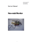
1
MAC 500 Version 2.2 Operator's Manual 2003361-004 USA Revision B Trademarks — Revision History Trademarked names appear throughout this document. Rather than list the names and entities that own the trademarks or insert a trademark symbol with each mention of the trademarked name, the publisher states that it is using the names only for editorial purposes and to the benefit of the trademark owner with no intention of improperly using the trademark. 900 SC, ACCUSKETCH, AccuVision, APEX , AQUA-KNOT, ARCHIVIST, Autoseq, BABY MAC, C Qwik Connect, CardioServ, CardioSmart, CardioSys, CardioWindow, CASE, CD TELEMETRY, CENTRA, CHART GUARD, CINE 35, COROLAN, CORO, COROMETRICS, Corometrics Sensor Tip, CRG PLUS, DASH, Digistore, Digital DATAQ, E for M, EAGLE, Event-Link, FMS 101B, FMS 111, HELLIGE, IMAGE STORE, INTELLIMOTION, IQA, LASER SXP, MAC, MAC-LAB, MACTRODE, MARQUETTE, MARQUETTE MAC, MARQUETTE MEDICAL SYSTEMS, MARQUETTE UNITY NETWORK, MARS, MAX, MEDITEL, MEI, MEI in the circle logo, MEMOPORT, MEMOPORT C, MINISTORE, MINNOWS, Monarch 8000, MULTI-LINK, MULTISCRIPTOR, MUSE, MUSE CV, Neo-Trak, NEUROSCRIPT, OnlineABG, OXYMONITOR, Pres-R-Cuff, PRESSURESCRIBE, QMI, QS, Quantitative Medicine, Quantitative Sentinel, RAC, RAMS, RSVP, SAM, SEER, SILVERTRACE, SOLAR, SOLARVIEW, Spectra 400, Spectra-Overview, Spectra-Tel, ST GUARD, TRAM, TRAM-NET, TRAM-RAC, TRAMSCOPE, TRIM KNOB, Trimline, UNION, STATION, UNITY logo, UNITY NETWORK, Vari-X, Vari-X Cardiomatic, VariCath, VARIDEX, VAS, and Vision Care Filter are trademarks of GE Medical Systems Information Technologies, Inc., registered in the United States Patent and Trademark Office. 12SL, 15SL, Access, AccuSpeak, ADVANTAGE, BAM, BODYTRODE, Cardiomatic, CardioSpeak, CD TELEMETRY®-LAN, CENTRALSCOPE, Corolation, Dash Port Docking Station, Dash Responder, EK-Pro, EDIC, Event-Link Cumulus, Event-Link Cirrus, Event-Link Nimbus, HI-RES, ICMMS, IMAGE VAULT, IMPACT.wf, INTER-LEAD, LIFEWATCH, Managed Use, MARQUETTE PRISM, MARQUETTE® RESPONDER, MENTOR, MicroSmart, MMS, MRT, MUSE CardioWindow, NST PRO, NAUTILUS, OCTANET, O2 SENSOR, OMRS, PHi-Res, Premium, Prism, QUIK CONNECT V. QUICK CONNECT, QT Guard, SMARTLOOK, SMART-PAC, Spiral Lok, Sweetheart, UNITY, Universal, Waterfall, and Walkmom are trademarks of GE Medical Systems Information Technologies, Inc. GE Medical Systems Information Technologies, Inc. 8200 West Tower Avenue Milwaukee, WI 53223 USA Tel: +1.414.355.5000 800.558.5120 (US only) Fax: +1.414.355.3790 GE Medical Systems Information Technologies GmbH Postfach 60 02 65 D-79032 Freiburg, Germany Tel: +49.761.45.43.0 Fax: +49.761.45.43.233 © GE Medical Systems Information Technologies, Inc., 2001, All rights reserved. Revision History This manual is subject to the GE Medical Systems Information Technologies (GEMS IT) change order service. The revision code, a letter that follows the document part number, changes with every update of the manual. Part No./ Revision Date Comment 2003361-004-A 2000-04 Initial Release / ECO 064 204 2003361-004-B 2001-06 ECO 067 433 2 MAC® 500 2003361-004-B How To Reach Us How To Reach Us Service Calls and Product Support To open a service call or obtain product support call the numbers below: 800.558.7044 561.575.5000 Have the following information available before calling: (US & Canada) (outside US) – part number of the defective part, or – model and serial number of the equipment, – or contact your representative or distributor. For other product information please contact one of the offices listed on the next page. – – Ordering Supplies & Service Parts Order supplies (leadwires, electrode paste, thermal paper, etc.) or service parts (manuals, circuit boards, cables, software, etc.) from: Accessories part number/name of the assembly where the item is used, item name, and where applicable, reference designation (e.g., R13, S12, U32). Ordering Manuals When ordering additional operator manuals, be sure to include the software version of the product. GE Medical Systems Accessories and Supplies 2607 North Grandview Blvd. Mail Code: SN-471 Waukesha, WI 53188 Telephone: 800.558.5102 (US only) 262.521.6856 (outside US) Fax: 800.232.2599 (US only) 262.521.6855 (outside US) Service parts GE Clinical Services P.O. Box 9100, 100 Marquette Drive Jupiter, FL 33468-9100 Telephone: 800.558.7044 (US only) 561.575.5000 (outside US) Fax: 800.421.6841 (US only) 561.575.5050 (outside US) 2003361-004-B MAC® 500 3 How To Reach Us Other Questions or Problems For additional information contact one of the offices listed below or see our website at www.gemedicalsystems.com. Japan GE Medical Systems, Japan 67-4 Takakura-cho Headquarters Hachiojii-shi, Tokyo 192-003, Japan GE Medical Systems Information Technologies 8200 West Tower Avenue Telephone: +81.42.648.2944 +0120-055-919 (toll free inside Japan only) Milwaukee, WI 53223 USA Fax: Telephone: 414.355.5000 or 800.558.5120 (US only) Hong Kong Fax: 414.355.3790 GE Medical Systems Hong Kong Limited +81.42.648.2902 11th Floor, The Lee Gardens Europe 33 Hysan Avenue GE Medical Systems Information Technologies Causeway Bay, Hong Kong Postfach 60 02 65 Telephone: +852.2100.6300 D-79032 Freiburg Germany Fax: +852.2100.6292 Telephone: +49.761.4543.0 Fax: +49.761.4543.233 Southeast Asia GE Pacific Australia 298 Tion Bahru Road #15-01/06 GE Medical Systems (Australia) Pty Ltd. Central Plaza, Singapore 168730 13 South Street Telephone: +65.277.7620 Rydalmere NSW 2116 Fax: +65.277.7600 Australia Telephone: +61.2.9975.5501 Fax: +61.2.9975.5503 4 MAC® 500 2003361-004-B General Information General Information • Standards compliance: European Council Directive 93/42/EEC IEC60601-1-2/EN 60601-1-2 "Electromagnetic Compatibility - Medical Electrical Equipment" CISPR11 / EN 55011 "Radio interference emission" IEC 60601, protection class I MDD class IIb • The symbol means: Consult accompanying documents. It indicates points which are of particular importance in the operation of the device. • The warranty does not cover damage resulting from the use of unsuitable accessories and consumables from other manufacturers. • On request GEMS IT will provide a service manual. • The GEMS IT quality management system complies with the standards EN ISO 9001 and EN 46001. 2003361-004-B MAC® 500 5 For your notes For your notes 6 MAC® 500 2003361-004-B Contents 1 INTRODUCTION TO THE MAC® 500 SYSTEM 9 2 CONTROLS AND INDICATORS 10 3 SAFETY INFORMATION, STARTUP AND PERFORMANCE TEST 12 4 PREPARATIONS FOR ECG RECORDING 20 5 12 LEAD MODE 23 6 3 LEAD MODE 32 7 AUTO RHYTHM MODE 35 8 HEART-RATE CONTROL 39 9 ECG RECORDING DURING DEFIBRILLATION / ECGS OF PACEMAKER PATIENTS 40 10 LOADING WRITER PAPER 41 11 THE SETUP MENU 43 12 CLEANING, DISINFECTION AND MAINTENANCE 46 13 TROUBLESHOOTING 47 14 TECHNICAL SPECIFICATIONS 48 INDEX 52 2003361-004-B MAC® 500 7 For your notes For your notes 8 MAC® 500 2003361-004-B ® Introduction to the MAC 500 System 1 Introduction to the MAC® 500 System The MAC® 500 is a compact 3-channel electrocardiograph for battery and line-power operation. The MAC® 500 has three operating modes: 12 Lead, 3 Lead and Auto Rhythm, and meets all demands on modern electrocardiographs. In the 12 Lead Mode the MAC® 500 simultaneously acquires 12 leads of ECG for a period of 10 seconds and then prints them out. You can choose between simultaneous and sequential recordings. In simultaneous recordings all leads represent the same period of time (either 10 seconds = long format, or 3 seconds = short format). 1.5 times the RR interval averaged over the 4 preceding QRS complexes. The MAC® 500 continues recording until the triggering event ceases. The first 30 seconds are recorded at the selected speed, then the recorder switches to a paper speed of 5 mm/s. Numerous device settings can be customized to meet each user's special requirements. The device is not intended for intracardial use. The device is not intended for use as a vital-signs physiological monitor. For sequential recordings the 10-second signal acquisition period is divided into 4 segments of 2.5 seconds each. The first 3 recorded leads represent the first segment (0-2.5 seconds), the second group of 3 leads represents the second segment (2.5 to 5 seconds), etc. Caution Patient Hazard Medical technical equipment such as the MAC® 500 must only be used by qualified and trained personnel. You can choose between the standard lead sequence and the CABRERA sequence for the recording. One version of the MAC® 500 comes with an ECG measurement program which, in the 12 Lead Mode, provides a patient data sheet with ECG measurement results (Figure 5-3). powe on/of r f sta sto stan db y bat te lowry rt copy p setu In the 3 Lead Mode the MAC® 500 records 3 leads of continuous ECG data (or 1 lead, if the default setting is changed in the setup menu). pro g mm 12 p 50 3 Hz /s mm With the Interpretation option activated, this version of the MAC® 500 will also print the interpretative statements after the measurement results (Figure 58). /m V Hz 20 25 HR ∆ 10 5 20/35 filter 5 Figure 1-1. The MAC® 500 system In the Auto Rhythm Mode the MAC® 500 will analyze the ECG and automatically starts recording − when the heart rate exceeds the set upper or lower limit − when QRS complexes are detected whose RR interval is shorter than 0.8 times or greater than 2003361-004-B MAC® 500 9 Controls and Indicators 2 Controls and Indicators 1 2 3 pow on/o er ff star t stop copy pro setu p g mm /s 12 mm /m 50 3 Hz V Hz 20 25 HR ∆ 20 filte/35 r 10 5 4 5 5 6 7 Hz standby battery low prog power on/off 12 copy 3 setup mm/s mm/mV 50 20 25 10 5 5 10 9 Hz 20/35 filter 8 start HR∆ stop 19 18 17 16 15 14 13 12 11 Figure 2-1. Controls and Indicators 10 MAC® 500 2003361-004-B Controls and Indicators Explanation of the signs and symbols used on the device 1 Cover of paper compartment 2 Spring lock to open the paper compartment 3 Power connector Observe the operator's manual 4 Patient cable connector (type CF, highly insulated, defibrillation-proof) Type CF signal input, highly insulated, 5 "battery low" indicator (yellow): when it lights up, the battery needs to be charged 6 defibrillation-proof Start "standby" indicator (green): when it lights up, the MAC® 500 is connected to the mains and operates on line power ECG lead 7 2-line character display Lead-fail indicator 8 Enables/disables muscle filter (20/35 Hz) 9 Gain selection keys - 5, 10, 20 mm/mV 10 Paper speed selection keys - 5, 25, 50 mm/s (5 mm/s only in 3 Lead and Auto Rhythm Modes) Stop heart rate (BPM) 11 Mode selection keys 12 Prints additional report copies (e.g. after change of lead sequence) and the 10-second ECG in Auto Rhythm Mode 13 Displays the setup menu 14 ECG lead selection in 3 Lead and Auto Rhythm Modes, cursor control keys for navigating in the setup menu 15 Enables/disables QRS beep, silences audio signals 16 Power switch (ON/OFF) 17 Starts and stops the recorder in the selected mode 18 Yellow indicator is lit when selected mode is disabled 19 Green indicator is lit when selected mode is enabled 2003361-004-B QRS beep/audio signals Cursor control, lead selection 12 12 Lead Mode 3 3 Lead Mode HR∆ Auto Rhythm Mode MAC® 500 11 Safety Information, Startup and Performance Test 3 Safety Information, Startup and Performance Test 3.1 Safety Information • This manual is an integral part of the device. It should always be kept near the device. Close observance of the information given in the manual is a prerequisite for proper device performance and correct operation and ensures patient and operator safety. Please note that information pertinent to several chapters is given only once. Therefore, carefully read the manual once in its entirety. Caution indicates a potentially hazardous situation which, if not avoided, may result in minor or moderate injury or product/property damage. • GEMS IT is responsible for the effects on safety, reliability, and performance of the device, only if − assembly operations, extensions, readjustments, modifications, or repairs are carried out by persons authorized by GEMS IT, • To ensure patient safety, the specified measuring accuracy, and interference-free operation, we recommend to use only original GEMS IT components. The user is responsible for application of unsuitable accessories from other manufacturers. • This manual is in conformity with the device specifications and standards on safety of electromedical equipment valid at the time of printing. All rights are reserved for devices, circuits, techniques, software programs, and names appearing in this manual. • The terms danger, warning, and caution are used throughout this manual to point out hazards and to designate a degree or level of seriousness. Hazard is defined as a source of potential injury to a person. − the electrical installation of the relevant room complies with the requirements of the appropriate regulations, and − the device is used in accordance with the instructions for use. The safety statements presented in this chapter refer to the equipment in general and, in most cases, apply to all aspects of the device. There are additional safety statements in the other chapters which are specific to the topic described. The order in which safety statements are presented in no way implies order of importance. DANGERS EXPLOSION HAZARD — Do not use this equipment in the presence of flammable anesthetics, vapors or liquids. Danger indicates an imminently hazardous situation which, if not avoided WILL result in death or serious injury. Warning indicates a potentially hazardous situation which, if not avoided, COULD result in death or serious injury. 12 MAC® 500 2003361-004-B Safety Information, Startup and Performance Test WARNINGS ACCESSORIES (SUPPLIES) — Use only the original GEMS IT cables. Do not connect other signal sources to the cables. The user is responsible for the use of accessories from other manufacturers. ACCIDENTAL SPILLS — To avoid electric shock or device malfunction liquids must not be allowed to enter the device. If liquids have entered a device, take it out of service and have it checked by a service technician before it is used again. BEFORE USE — Before putting the system into operation visually inspect all connecting cables for signs of damage. Damaged cables and connectors must be replaced immediately. BEFORE USE — Before using the device, the operator must verify that it is in correct working order and operating condition. For instructions, refer to section 3.3 “Testing the Performance” in this chapter. CONDUCTIVE CONNECTIONS — Do not allow electrodes to come into contact with conductive parts. The neutral electrode, in particular, must not be connected to earth. MPSO—The use of a multiple portable socket outlet (MPSO) for a system will result in an enclosure leakage current equal to the sum of all individual earth leakage currents of the system if there is an interruption of the MPSO protective earth conductor. Do not use an additional extension cable with the MPSO as it will increase the chance of the single protective earth conductor interruption. OPERATOR — The user must have received adequate training in the use of the MAC® 500 and must be capable of applying it properly. POWER SUPPLY — The device must be connected to a properly installed power outlet with protective earth contacts only. If the installation does not provide for a protective earth conductor, disconnect the monitor from the power line and operate it on battery power, if possible. If the installation of this equipment in the USA will use 240V rather than 120V, the source must be a center-tapped, 240V, single phase circuit. DISCONNECTION FROM MAINS — When disconnecting the system from the power line, remove the plug from the wall outlet first. Then you may disconnect the power cord from the device. MOISTURE CONDENSATION — Devices intended for emergency application must not be stored or transported at temperatures which cause moisture condensation at the application site. Wait until all moisture condensation has evaporated before using the device. 2003361-004-B MAC® 500 13 Safety Information, Startup and Performance Test CAUTIONS MAINTENANCE — Regular preventive maintenance should be carried out annually, inspections of equipment with measuring functions should be done every two years (refer to chapter 12 “Cleaning, Disinfection and Maintenance”). PERFORMANCE CHECKS — Check the device performance once a month, strictly following the instructions outlined in section 3.3 “Testing the Performance”. POWER REQUIREMENTS — Before connecting the device to the power line, check that the voltage and frequency ratings of the power line are the same as those indicated on the unit’s label. If this is not the case, do not connect the system to the power line until you adjust the unit to match the power source. VENTILATION REQUIREMENTS — Set up the device in a location which affords sufficient ventilation. The ventilation openings of the device must not be obstructed. The ambient conditions specified in the technical specifications must be ensured at all times. EMC — Magnetic and electrical fields are capable of interfering with the proper performance of the device. For this reason make sure that all external devices operated in the vicinity of the monitor comply with the relevant EMC requirements. X-ray equipment or MRI devices are a possible source of interference as they may emit higher levels of electromagnetic radiation. INTERFACING OTHER EQUIPMENT — Devices may only be interconnected with each other or to parts of the system when it has been determined by qualified biomedical engineering personnel that there is no danger to the patient, the operator, or the environment as a result. In those instances where there is any element of doubt concerning the safety of connected devices, the user must contact the manufacturers concerned (or other informed experts) for proper use. In all cases, safe and proper operation should be verified with the applicable manufacturer’s instructions for use, and system standards IEC 60601-1-1/EN 60601-1-1 must be complied with. DEFIBRILLATOR PRECAUTIONS — Patient signal inputs labeled with the CF and BF symbols with paddles are protected against damage resulting from defibrillation voltages To ensure proper defibrillator protection, use only the recommended cables and leadwires. Proper placement of defibrillator paddles in relation to the electrodes is required to ensure successful defibrillation. DISPOSAL — Dispose of the packaging material, observing the applicable waste control regulations and keeping it out of children’s reach. ELECTROCAUTERY PRECAUTIONS — To prevent unwanted skin burns, apply electrocautery electrodes as far as possible from all other electrodes, a distance of at least 15 cm/ 6 in. is recommended. 14 MAC® 500 2003361-004-B Safety Information, Startup and Performance Test NOTES Literature ® - The MAC 500 is designed to comply with IEC 60601/ EN 60601 requirements. It is Class I equipment/equipment with a built-in rechargeable electrical power source. The device is not suitable for intracardiac use. The device is suitable for continuous operation. - Choose a location which affords an unobstructed view of the monitor’s screen and easy access to the operating controls. - The MAC® 500 has no additional protection against ingress of water. - Medical technical equipment such as the MAC® 500 must only be used by persons who have received adequate training in the use of such equipment and who are capable of applying it properly. Medical Device Directive 93/42/EEC EN 60601-1/1990 + A1: 1993 + A2: 1995: Medical electrical equipment. General requirements for safety EN 60601-1-1/9.1994 + A1 12.95: General requirements for safety. Requirements for the safety of medical electrical systems. Requirements for the safety of medical electrical systems. EN 60601-2-25/1993: Medical electrical equipment. Part 2: Special requirements for the safety of electrocardiographs. IEC Publication 513/1994: Fundamental aspects of safety standards for medical equipment. - At the end of its service life; the MAC® 500 and its accessories must be disposed of in compliance with the special waste control regulations for electronic parts. If you have any questions in this matter, please contact GEMS IT Medical Systems. 2003361-004-B MAC® 500 15 Safety Information, Startup and Performance Test ® 3.2 Starting Up the MAC 500 5 6 Power Supply Hz standby battery low prog copy setup 12 3 HR∆ mm/s mm/mV 50 20 25 10 5 5 Hz 20/35 filter − The MAC® 500 operates on line power or on power from the rechargeable battery. − The battery is automatically charged when the device is connected to the power line (indicator 6 (Figure 3-1) is lit when the battery is charging). It is not necessary to turn the device on for charging. In order to have the battery fully charged at all times, leave the MAC® 500 connected to the power line. A depleted battery needs 6 hours to recharge. − Indicator (5) lights up when the battery needs charging. − A new, fully charged battery provides power to record at least 50 12 Lead ECGs. Have the battery replaced by a service technician when the capacity drops to about 25 recordings. Figure 3-1. Indicators Starting Up and Connecting the MAC® 500 − The MAC® 500 must not be used or stored in moist and/or dusty rooms. Further, it must not be exposed to direct sunlight or other sources of heat. − Figure 3-2 shows a practical arrangement between patient and recorder. For interferencefree operation, it is important that the patient cable and the power cord do not run parallel. Figure 3-2. Arranging the MAC® 500 and examination couch • Use the power cord to connect the recorder to the power line (Figure 3-3). Use only the original power cord or an equivalent cable. The MAC® 500 is shipped with a fully charged battery. Please note that the battery needs to be charged when the battery indicator (5) lights up. • Insert writer paper as described in chapter 10. MAC® 500 2003361-004-B Figure 3-3. Power input 16 Safety Information, Startup and Performance Test 3.3 Testing the Performance • standby 18 16 On power up the device runs an automatic self-test. It defaults to the 12 Lead Mode (Figure 3-5), unless a malfunction is identified. If a malfunction is detected, the system will display an error message. Contact GEMS IT Service for further information. battery low power on/off Using the power switch (16), turn on the MAC® 500. The yellow indicator (18) lights up. copy setup When a patient cable is not connected, two ^^ symbols appear on the display in place of the leadfail indicator. Also, the MAC® 500 will emit an audio signal to inform you that the cable is missing. start stop The ^^ symbols on the display disappear as soon as you connect the cable. At the same time the lead-fail Figure 3-4. Operating controls and indicators detection function is enabled. The MAC® 500 will again emit an audio signal and alert you to one of the missing electrodes, until a patient is connected. The audio signal can be silenced with Hz . After application of all required electrodes, the MAC® 500 automatically enables the HR indication function (chapter 8 "Heart-Rate Control"). prog mm/s mm/mV Hz Figure 3-5. Display after successful MAC® 500 selftest 2003361-004-B MAC® 500 17 Safety Information, Startup and Performance Test 3.4 Selecting the Language, Customizing the Recorder Selecting the Language For the displayed texts and reports you can choose among various languages. standby • battery low 12 copy setup to display the language selection menu: Figure 3-7 will appear. prog power on/off Press • Use the cursor keys to select the language and confirm your selection with . 3 setup start • Exit the menu with setup . HR∆ stop Figure 3-6. Controls required for language selection Hz prog mm/s mm/mV Hz Figure 3-7. Selected language 18 MAC® 500 2003361-004-B Safety Information, Startup and Performance Test Customizing the Device Settings Parameter Default Options Language [English] further languages Notation [AAMI] IEC Leads [Standard] Cabrera Report format [Sequential] Simultaneous - when choosing "sequential" Rhythm lead - when choosing "simultaneous" [Yes] No [Short] Long Override Mode [On] Off Patient Data sheet* [No] Yes Leads [3] 1 Speed [25] 50 Sensitivity [10] 5, 20 AC Filter [60] 50, off Muscle Filter [On] Off Muscle Filter [35] 20 The MAC® 500 allows you to customize numerous settings to suit your personal needs and preferences. The MAC® 500 will save these settings as the user defaults and will activate them each time it is turned on. Figure 3-8 lists all settings that can be customized, the middle column shows the factory defaults. Please refer to chapter 11 "The Setup Menu" for a detailed explanation of how to customize the device settings. ADS (cubic spline) [On] Off HR Control [On] Off HR-Control [45], [130] 30 to 120, 80 to 240 Cut-off Frequency [0.08] 0.04; 0.16 Contrast QRS Beep < reduce, > increase [2] (medium) 0 (off), 1 (low), 3 (loud) Date Time Option no.** for "Interpretation" option Factory Defaults [No] Yes Print [No] Yes (printout of all settings) Figure 3-8. The MAC® 500 setup menu (on the display the active selections are shown in angular brackets [ ]) * not part of MAC® 500 with measurement program ** only for MAC® 500 with measurement program 2003361-004-B MAC® 500 19 Preparations for ECG Recording 4 Preparations for ECG Recording 4.1 Connecting the Patient Cable The 10-lead cable is used for acquisition of the standard ECG leads (Standard, Augmented, Chest). • Warning Shock Hazard For reasons of safety, use only the original GEMS IT patient cables. Do not connect other signal sources to the cable. Connect the patient cable to the ECG signal input (4, Figure 4-1). When a patient cable is not connected, two ^^ symbols appear on the display in place of the leadfail indicator. Also, the MAC® 500 will emit an audio signal to inform you of the missing cable. The ^^ symbols disappear as soon as you connect Note The signal input is highly insulated and defibrilla- the cable. At the same time the lead-fail detection tion-proof (only if the original GEMS IT patient function is enabled. The MAC® 500 will again emit cables are used). These patient cables ensure patient an audio signal and alert you to one of the missing safety and protect the device during defibrillation electrode, until a patient is connected. The audio and electrosurgery. signal can be silenced with . After application of all required electrodes, the MAC® 500 automatically enables the HR indication function (chapter 8 "Heart-Rate Control"). 4 Figure 4-1. ECG signal input (type CF, highly insulated, defibrillation proof) 20 MAC® 500 2003361-004-B Preparations for ECG Recording 4.2 Applying the Electrodes Note Applying Electrodes (Limb Leads) Use silver-silver chloride electrodes when recording lated. (Refer to chapter 9 "ECG Recording During Careful application of the electrodes is the key to an interference-free ECG. Defibrillation" for details.) Refer to the illustration shown in Figure 4-2. the ECG of a patient who may have to be defibril- RA (white) LA (black) LL (red) RL (green) V RA Applying Suction Electrodes (Thorax) LA • RL LL V2 V3 V5 V4 Shave and clean application points, if necessary. Application Points for Standard Leads (I, II, III, aVR, aVL, aVF, V1 to V6) Figure 4-2. Applying limb-lead electrodes V1 electrode on right arm electrode on left arm electrode on left leg electrode on right leg Four limb and six chest electrodes must be applied for the acquisition of the standard leads. Attach the limb electrodes above the wrists and ankles. Figure 4-3 shows the chest lead application points. V1 in the 4th intercostal space at the right sternal edge V6 V2 in the 4th intercostal space at the left sternal edge V6 V1 V2 V3 V4 V3 on the level of the 5th rib midway between between V2 and V4 V5 Figure 4-3. Chest electrode application points RL green RA white V4 in the 5th intercostal space on the left midclavicular line V5 on the left anterior axillary line between V4 and V6 right leg right arm V1 brown V1 V2 brown V3 brown V2 V3 V5 V6 on the mid-axillary line at the level of V4 V6 V4 Connect the 10-wire patient cable as shown in Figure 4-4. V4 brown V5 brown V6 brown LA black left arm LL red V6 left leg V1 V2 V3 V4 Shock Hazard Avoid contact between electrodes and conductive parts The neutral electrode, in V5 Figure 4-4. Connecting the patient cable (10-lead cable, standard leads) 2003361-004-B Warning MAC® 500 particular, must not come into contact with ground. 21 Preparations for ECG Recording Artifact Due to Poor Electrode Application This device is equipped with state-of-the-art electronic utilities to insure artifact-free recording. Among these are the automatic baseline adjustment and the anti-drift system (ADS). At the beginning of the recording the automatic baseline adjustment verifies the incoming signal and adjusts the baseline position accordingly. During recording the anti-drift system continuously checks the baseline position and returns the baseline to its normal level if it wanders (Figure 4-5). When electrodes are not properly applied, these measures may not fully compensate for artifact. High polarization voltages induced by electrodes applied without conductive gel may cause the amplifier to overrange, so that a straight line will be recorded instead of the ECG (see Figure 4-5). ADS will return this line to its normal position, and a baseline ensues for approx. 1 second. Blocking can be initiated manually by disconnecting the RA electrode. Remedy • • • • • Apply the electrodes according to instructions. Do not apply the electrodes on top of clothing. Use a contact agent (moist electrode paper, electrode cream, spray, etc.). Wait approx. 10 seconds before initiating a recording. After the 10-second period the polarization voltages have stabilized, provided the electrodes are properly applied. If this is not the case, the electrode concerned is indicated on the display (RL, RA, LA, LL, V1 to V6). If it becomes necessary to verify the raw ECG signal, switch off the ADS function and all filters (35 Hz/20 Hz muscle filter, AC filter). approx.1 s Figure 4-5. Sample recording 22 MAC® 500 2003361-004-B 12 Lead Mode 5 12 Lead Mode 5.1 The Basics Note − With the factory defaults unchanged, the HR indication function is active in all operating modes. The HR limit values are 45 BPM and 130 BPM. These limits can be changed from the setup menu. Further details on this subject can be found in chapter 8 "Heart-Rate Control" and chapter 11 "The Setup Menu". − At least 4 QRS complexes are required for correct determination of the heart rate. − In the presence of lead failure the MAC 500 will operate in the 12 Lead Mode only if "Override" is enabled in the setup menu (chapter 11 "The Setup Menu"). ® Warning Patient Hazard The MAC 500 is not intended for use as a vital signs physiological ® monitor. 2003361-004-B In the 12 Lead Mode the MAC® 500 simultaneously acquires 12 leads of ECG for a period of 10 seconds. When initiated with the key, the recording proceeds automatically. Furthermore it measures the ECG and documents the results on the ECG report. You can choose between sequential and simultaneous recordings. For sequential recordings the 10-second signal acquisition period is divided into 4 segments of 2.5 seconds each. The first 3 recorded leads represent the first segment (0-2.5 seconds), the second group of 3 leads represents the second segment (2.5 to 5 seconds), etc. In simultaneous recordings all leads represent the same period of time (either 10 seconds = long format, or 3 seconds = short format). You can choose between the standard and the CABRERA lead sequences for recording (chapter 11 "The Setup Menu"). With the factory defaults unchanged, the MAC® 500 will write a sequential 12 lead ECG followed by a rhythm strip (leads II, aVF, V5). The MAC® 500 with the optional measurement program will also print a patient data sheet including measurement results. MAC® 500 23 12 Lead Mode 5.2 Recording a b c d e Hz prog mm/s j i mm/mV Hz g f h Figure 5-1. 12 Lead mode display a Lead sequence (Stnd = standard, Cab1 = CABRERA) b Lead-fail indication c QRS indicator d Heart rate e AC line filter (60 Hz) enabled f Muscle filter (35 Hz) enabled g Gain h "Collecting Data" indicator i Paper speed j Operating mode Upon power up, the MAC® 500 defaults to the 12 Lead Mode. − Having first applied the electrodes, please wait about 10 seconds for the signal to stabilize (see "Artifact Due to Poor Electrode Application" in section 4.2). With the factory defaults unchanged, the MAC® 500 selects the following functions and settings after power up (the most important settings are indicated on the display, Figure 5-1): − the "Standard" lead sequence (I, II, III, aVR, aVL, aVF, V1 to V6; Stnd = Standard, Cab1 = CABRERA) - a − a gain of 10 mm/mV - g − a paper speed of 25 mm/s - i − the AC line filter (60 Hz) is active - e − the muscle filter (35 Hz) is active - f − the anti-drift system (cubic spline) is enabled − the report format is sequential and includes the rhythm leads (and patient data sheet – MAC® 500 with optional measurement program) − pressing copy initiates repeated printouts of the ECG *RA* right arm electrode disconnected *V2* chest electrode V2 disconnected − Before starting the recording with , check that there is no lead-fail indication on the display - b, Figure 5-1. If the lead-fail message persists after you have checked the electrode connections, there could be a break in the patient cable and the cable should be replaced. Also check the paper supply. *V3* chest electrode V3 disconnected − Press *LA* left arm electrode disconnected *LL* left leg electrode disconnected *RL* right leg electrode disconnected *V1* chest electrode V1 disconnected to initiate the recording. *V4* chest electrode V4 disconnected *V5* chest electrode V5 disconnected *V6* chest electrode V6 disconnected Messages indicating disconnected electrodes 24 MAC® 500 2003361-004-B 12 Lead Mode 1 MAC 500 V2.2 GEMS IT I aVR II aVL III aVF 2 Jan.14 2000 01:55pm 12Ld 25mm/s 10mm/mV ADS 60Hz 0.08-35Hz 60BPM 3 4 5 6 7 8 9 Figure 5-2. ECG recording (12 Lead Mode, factory defaults) 1 Date/time 2 Calibration pulse 3 Operating mode 4 Paper speed 5 Gain 6 ADS enabled 7 AC filter enabled (60 Hz) 8 Signal transmission range (low cut-off frequency at 0.08 Hz - adjustable, high cut-off frequency at 35 Hz - muscle filter enabled) 9 Heart rate 2003361-004-B MAC® 500 25 12 Lead Mode At the end of the data collection period, the MAC® 500 will record the ECG (Figure 5-2). Note The following parameters cannot be changed before printing out additional report copies − AC line filter − muscle filter − The ECG recording can be stopped at any time . with − Copies of the same ECG can be printed out with copy − ADS. . Before printing a copy you can – change the gain with mm/mV, – change the paper speed with mm/s, – change the sequence of recorded leads ( ). The display indicates the leads recorded a b c d e Hz prog mm/s j i mm/mV Hz g f h Figure 5-1. 12 Lead mode display (repeated) a Lead sequence (Stnd = standard, Cab1 = CABRERA) b Lead-fail indication c QRS indicator d Heart rate e AC line filter (60 Hz) enabled f Muscle filter (35 Hz) enabled g Gain h "Collecting Data" indicator i Paper speed j Operating mode 26 first - a, Figure 5-1. The normal lead sequence is "Standard" Stnd = standard Aug = augmented V1-V3 = V1, V2, V3 V4-V6 = V4, V5, V6 or CABRERA Cab1 = aVL, I, -aVR Cab2 = II, aVF, III V1-V3 = V1, V2, V3 V4-V6 = V4, V5, V6 When starting with the augmented leads, the recording sequence is Aug V1-V3 V4-V6 Stnd MAC® 500 = = = = augmented V1, V2, V3 V4, V5, V6 standard 2003361-004-B 12 Lead Mode 5.3 Report Documents The length and scope of the reports depends on the selected lead sequence and on the selected report format (chapter 11 "The Setup Menu"). The illustrations below show examples of the default formats. Sequential Recordings In sequential recordings the standard leads are followed by the rhythm leads and, if you are using the MAC® 500 with the optional measurement program, the patient data sheet which includes the measurement results (Figure 5-3). Instead of the standard leads, the CABRERA lead sequence can be recorded (aVL, I, -aVR, II, aVF, III). I aVR V1 V4 II aVL V2 V5 III aVF V3 V6 II II II aVF aVF aVF V5 V5 V5 GEMS IT Serial No : Jan. 14 00 02:21pm Last Name First Name Date of Birth Sex : : : : Measurement Results: QRS QT/QTC PR P RR/PP P/QRS/T MAC 500 : : : : : : 108ms 366 / 427ms 170ms 162ms 724 / 146ms 67/ 66/ 65Degrees V2.2 12SL V 13 Figure 5-3. Lead sequence standard Report format sequential (rhythm leads default — can be disabled; measurement results only with the MAC® 500 with optional measurement program) 2003361-004-B MAC® 500 27 12 Lead Mode Simultaneous Recordings I aVR V1 V4 II aVL V2 V5 III aVF V3 V6 Figure 5-4. Lead sequence standard Report format simultaneous, short (3 seconds) aVL II V1 V4 I aVF V2 V5 -aVR III V3 V6 Figure 5-5. Lead sequence CABRERA Report format simultaneous, short (3 seconds) 28 MAC® 500 2003361-004-B 12 Lead Mode I I I II II II III III III aVR aVR aVR aVL aVL aVL aVF aVF aVF V1 V1 V1 V2 V2 V2 V3 V3 V3 V4 V4 V4 V5 V5 V5 V6 V6 V6 Figure 5-6. Lead sequence standard Report format simultaneous, long (10 seconds) 2003361-004-B MAC® 500 29 12 Lead Mode aVL aVL aVL I I I -aVR -aVR -aVR II II II aVF aVF aVF III III III V1 V1 V1 V2 V2 V2 V3 V3 V3 V4 V4 V4 V5 V5 V5 V6 V6 V6 Figure 5-7. Lead sequence CABRERA Report format simultaneous, long (10 seconds) 30 MAC® 500 2003361-004-B 12 Lead Mode Recording of the Interpretative Statements (Option) 5.4 Brief Operating Instructions (12 Lead Mode) With the Interpretation option activated, the MAC® 500 will print the interpretative statements after the measurement results. Since it is not possible to enter the patient's age, the MAC® 500 always interprets data as an adult ECG. For a detailed description of the ECG measurement and interpretation program, refer to our publication GE Marquette 12SL Physician's Guide (part no. 000-90160-010). In chapter 11 "The Setup Menu" you will find detailed information on activating the interpretation option. • • GEMS IT Jan.11 00 02:21pm Interpretation: • Switch on device and wait for self-test to end Apply electrodes to the patient, connect patient cable to device Check device settings − lead sequence − report format Modify device settings, if required, using the appropriate function key or setup • Wait for patient to lie motionless • Start signal acquisition and recording with Unusual P axis, possible ectopic atrial tachycardia Left axis deviation Left ventricular hypertrophy with QRS widening and repolarization abnormality Inferior infarct, age undetermined Abnormal ECG MAC 500 V2.2 12SL V 13 Figure 5-8. Interpretation 2003361-004-B MAC® 500 31 3 Lead Mode 6 3 Lead Mode 6.1 The Basics In the 3 Lead Mode the MAC® 500 simultaneously Note records 3 leads of ECG in real-time (factory default, With the factory defaults unchanged, the HR the device can also be set up to record one ECG indication function is active in all operating modes. lead). The recording is started and stopped with the The HR limit values are 45 BPM and 130 BPM. key. These limits can be changed from the setup menu. Further details on this subject can be found in chapter 8 "Heart-Rate Control" and chapter 11 "The Setup Menu". Some of the device settings can be customized, either directly with the appropriate key or from the setup menu (chapter 11 "The Setup Menu"). 6.2 Recording Warning Patient Hazard The device is not intended for use as a vital-signs physiological monitor. a b c d e Hz Switch on the MAC® 500 and select the 3 Lead Mode with 3 . With the factory defaults unchanged, the MAC® 500 selects the following functions and settings (the most important settings are indicated on the display, Figure 6-1): − the "Standard" lead sequence (I, II, III, aVR, aVL, aVF, V1 to V6; Stnd = Standard, Cab1 = CABRERA) - a prog mm/s i h mm/mV g Hz f Figure 6-1. 3 Lead mode display a Lead sequence b Lead-fail indication c QRS indicator d Heart rate e AC line filter (60 Hz) enabled f Muscle filter (35 Hz) enabled g Gain h Paper speed i Operating mode 32 − a gain of 10 mm/mV - g, the setting can be changed any time with the gain keys - 9, Figure 6-2 − a paper speed of 25 mm/s - h, the paper speed can be changed any time with the speed keys - 10, Figure 6-2 − the AC line filter (60 Hz) is active - e − the muscle filter (35 Hz) is active - f, it can be disabled any time with the muscle filter key - 8, Figure 6-2 − the anti-drift system (cubic spline) is enabled MAC® 500 2003361-004-B 3 Lead Mode Hz − Before starting the recording with , check that there is no lead-fail indication on the display standby - b, Figure 6-1. If the lead-fail message persists battery low prog mm/s mm/mV after you have checked the electrode connections, Hz there could be a break in the patient cable and the copy 12 50 20 25 10 20/35 filter cable should be replaced. Also check the paper supply. setup 3 HR∆ 5 • Press to initiate the recording. You can stop the recording by pressing the same key 5 again. 10 9 Figure 6-2. Controls and indicators *RA* right arm electrode disconnected 8 − If you change the paper speed, gain, the lead group or the filter settings during a recording, the MAC® 500 briefly interrupts the recording, advances the paper and then resumes recording with the new settings. − The arrow keys *RL* right leg electrode disconnected *V1* chest electrode V1 disconnected *V2* chest electrode V2 disconnected can be used to switch to the next 3 leads of the selected se- *LA* left arm electrode disconnected *LL* left leg electrode disconnected and quence. − If the Anti-Drift System (ADS) is enabled, there will be a short delay before recording starts. The system needs this time to activate the ADS function. *V3* chest electrode V3 disconnected *V4* chest electrode V4 disconnected *V5* chest electrode V5 disconnected *V6* chest electrode V6 disconnected Messages indicating disconnected electrodes 2003361-004-B MAC® 500 33 3 Lead Mode 6.3 Brief Operating Instructions (3 Lead Mode) • • Switch on device and wait for self-test to end Apply electrodes to the patient, connect patient cable to device • Select 3 Lead Mode • Check device settings 3 − lead sequence ( setup ) − speed (50, 25, 5 mm/s) − gain (20, 10, 5 mm/mV) Modify device settings, if required, using the appropriate function key or 34 setup . • Start recording with • Select next lead group with • Enable/disable muscle filter with MAC® 500 20/35 filter 2003361-004-B Auto Rhythm Mode 7 Auto Rhythm Mode 7.1 The Basics Warning Patient Hazard The MAC 500 is not intended for ® use as a vital signs physiological monitor. In the Auto Rhythm Mode the MAC® 500 continuously scans the ECG and initiates a recording, if it detects specific conditions. The event that triggers the recording is always documented with "context", since the MAC® 500 also records the 5-second segment preceding the event. The recording continues as long as the condition exists. The first 30 seconds are recorded at the selected paper speed, then the recorder selects a speed of 5mm/s. Conditions that initiate a recording are − a heart rate exceeding one of the set limit values − QRS complexes with an RR interval shorter than 0.8 times or greater than 1.5 times the RR interval averaged over the 4 preceding RR intervals. The default heart-rate limits are 45 BPM and 130 BPM. These limits can be changed from the setup menu. Further details on this subject can be found in chapter 11 "The Setup Menu". The heart-rate indication function can be disabled from the setup menu, but this would only affect the 12 Lead and 3 Lead Modes. The function cannot be disabled for the Auto Rhythm Mode. The audio signal that the MAC® 500 emits when the heart rate exceeds either limit can be silenced with (chapter 8 "Heart-Rate Control"). 2003361-004-B MAC® 500 35 Auto Rhythm Mode a b c d 7.2 Recording e • Hz prog mm/s i h mm/mV Rhythm Mode with copy setup 3 HR∆ 50 20 25 10 5 5 10 . − the "Standard" lead sequence (I, II, III, aVR, aVL, aVF, V1 to V6 — as selected; Stnd = Standard, Cab1 = CABRERA) - a f Figure 7-1. Auto Rhythm mode display a Lead sequence b Lead-fail indication c QRS indicator d Heart rate e AC line filter (60 Hz) enabled f Muscle filter (35 Hz) enabled g Gain h Paper speed i Operating mode 12 HR∆ With the factory defaults unchanged, the MAC® 500 selects the following functions and settings (the most important settings are indicated on the display, Figure 7-1): Hz g Switch on the MAC® 500 and select the Auto 20/35 filter − a gain of 10 mm/mV - g, the setting can be changed any time with the gain keys - 9, Figure 7-2) − a paper speed of 25 mm/s - h, the paper speed can be changed any time with the speed keys - 10, Figure 7-2 − the AC line filter (60 Hz) is active - e O 9 Figure 7-2. Controls and indicators − the muscle filter (35 Hz) is active - f, it can be disabled any time with the muscle filter key - 8, Figure 7-2 − the anti-drift system (cubic spline) is enabled , check − Before starting the recording with that there is no lead-fail indication on the display - b. If the lead-fail message persists after you have checked the electrode connections, there could be a break in the patient cable and the cable should be replaced. Also check the paper supply. • *RA* right arm electrode disconnected *LA* left arm electrode disconnected Press to initiate the recording. You can stop the recording by pressing the same key again. *LL* left leg electrode disconnected *RL* right leg electrode disconnected *V1* chest electrode V1 disconnected *V2* chest electrode V2 disconnected *V3* chest electrode V3 disconnected *V4* chest electrode V4 disconnected *V5* chest electrode V5 disconnected *V6* chest electrode V6 disconnected Messages indicating disconnected electrodes 36 MAC® 500 2003361-004-B Auto Rhythm Mode Name:................................ I GEMS IT Jan.11 00 09:21am 1 II II III 2 II III III HR^ 25mm/s 10mm/mV Name:................... I I ADS 60Hz Figure 7-3. Auto Rhythm-recording 1 History 2 Triggering event 0.08-35Hz 117BPM HR^ 25mm/s 10mm/mV Upon program start, the MAC® 500 writes a 7-inch strip of the selected lead group. Then the recorder stops and starts analyzing the ECG. If the analysis algorithm detects one of the conditions described above, this event is recorded with a history of 5 seconds (Figure 7-3). The recording continues as long as the condition exists. The first 30 seconds are recorded at the selected paper speed, then the recorder selects a speed of 5 mm/s. The recording can be stopped any time with the key. When there is no paper left in the recorder, the program stops automatically and the recorder will beep at 10-second intervals to alert the user to this condition. Note The recording can be stopped any time with the key. Between events, a 10-second recording of the Warning selected lead group can be initiated with copy . Patient Hazard When there is no paper in the recorder, the program stops automatically and the If the heart rate exceeds one of the set limit values, recorder will beep at 10-second intervals. the MAC® 500 emits an audio signal. This signal can be silenced with Note Information may be lost due to the pause following a change of the device settings. . − If you change the paper speed, gain or the filter settings during a recording, the MAC® 500 briefly interrupts the recording, advances the paper and then resumes recording with the new settings. − If the Anti-Drift System (ADS) is enabled, there will be a short delay before recording starts. 2003361-004-B MAC® 500 37 Auto Rhythm Mode 7.3 Brief Operating Instructions (Auto Rhythm Mode) • • Switch on device and wait for self-test to end Apply electrodes to the patient, connect patient cable to device • Select Auto Rhythm Mode - • Check device settings – lead sequence - HR∆ setup – speed (50, 25, 5 mm/s) – gain (20, 10, 5 mm/mV) Modify device settings, if required, using the appropriate function key or 38 setup • Start program with • Select lead group with • Enable/disable muscle filter with MAC® 500 20/35 filter 2003361-004-B Heart-Rate Control 8 Heart-Rate Control The Basics Warning Patient Hazard The MAC 500 is not intended ® for use as a vital signs physiological monitor. The MAC® 500 will control the heart rate in all operating modes, even when not recording. This automatic control function can be disabled from the setup menu (chapter 11 "The Setup Menu"). It is also possible to modify the heart-rate limits. The factory defaults are 45 and 130 BPM. If the heart rate exceeds one of the set limit values, the MAC® 500 will emit an audio signal (alternating beep). This audio signal will cease − automatically when the heart rate returns to the permitted range − when you press the key. The audio signal will not recur if it was silenced with . Only when the heart rate exceeds one of the limit values anew, will the audio signal recur. Selecting HR Limit Values • Press setup . Figure 8-1 will appear. Hz • Keep pressing until the display shown in Figure 8-2 appears. The cursor flashes on the low limit value. Using the cursor keys prog mm/s mm/mV Hz Hz prog mm/s Figure 8-2. HR limit menu 2003361-004-B mm/mV steps of 5 BPM between 30 and 120 BPM. • Figure 8-1. Language selection menu Hz , you can change this value in Press to confirm your selection, or to skip this menu option. • Adjust the high limit value in the same way (between 80 and 240 BPM). • Again, confirm the entry with • Press MAC® 500 setup . to exit the menu. 39 ECG Recording During Defibrillation / ECGs of Pacemaker Patients 9 ECG Recording During Defibrillation / ECGs of Pacemaker Patients ECG Recording During Defibrillation ECGs of Pacemaker Patients The patient signal input is defibrillation-proof. Therefore it is not necessary to remove the patient cable during defibrillation. Due to the slow paper speed it is not possible to display pacing pulses directly on the ECG recording. At a paper speed of 50 mm/s and a pulse duration of just 0.5 ms, the width of the recorded pacing pulse would be a mere 0.025 mm. When using stainless steel or silver electrodes, however, the defibrillator discharge current may cause complete polarization at the electrode/skin interface. This will block acquisition of the ECG signal for several minutes. You can avoid this effect by using silver/silver-chloride electrodes. Select the 3 Lead Mode, if defibrillation is carried out during ECG recording and disable the anti-drift system as it causes a signal delay of approx. 4 seconds (chapter 11 "The Setup Menu"). If electrodes made of other materials are used, we recommend disconnecting the patient cable from the recorder while the shock is delivered. For this reason the MAC® 500 adapts the pulse amplitude and pulse width for recording, so that the pacing pulse is easier to identify. The MAC® 500 records the pulse with the correct polarity and a width of 5 ms. The pulse amplitude is the same in all leads (depending on the polarity of the pacing pulse in leads I and II, the pacing pulse in lead III may be suppressed). The charge reversal waveform may differ slightly between leads. Figure 9-1 shows an ECG recording with pacing pulses. Warning Warning − Shock Hazard For safety reasons, use only the original GEMS IT patient cables. Before connecting the cable to the device, check it for signs of mechanical damage. Do not use a damaged cable. − Shock Hazard Observe the safety information given in the operator manual of the defibrillator used. − Shock Hazard During defibrillation, do not touch the patient, the electrodes or the leadwires. Patient Hazard If several adverse conditions exist at once, the possibility that the pacer pulses are interpreted (and counted) as QRS complexes should be considered. At the same time, however, QRS complexes might be suppressed in certain situations. Therefore, pacemaker patients should always be watched closely. Caution Patient Hazard, Equipment Damage The patient signal input of the device is protected against damage from defibrillation voltages. Nevertheless, caution is advised when using defibrillators at the same time as other equipment connected to the Figure 9-1. ECG recording with pacing pulses patient. 40 MAC® 500 2003361-004-B Loading Writer Paper 10 Loading Writer Paper • • Note Use only the original GEMS IT writer paper. This paper is specifically designed to prevent • electrostatic build up and debris collection on the thermal array printhead. Using other papers may result in recordings of poor quality and/or premature wear of the printhead. Use of other paper may • void the warranty. • Caution Risk of Skin Burns Take care not to touch the Switch on the device. Press on the spring lock of the paper compartment to open the door (Figure 10-1). Remove the sleeve of the previous paper roll and the plastic axle. Slide new roll on axle and insert as shown in Figure 10-2. Unroll a length of paper and close the door (Figure 10-3), taking care that the paper is exactly positioned on the pressure roller and that the door locks into place on both sides. thermal printhead when inserting the paper. After prolonged periods of recording there is a risk of skin burns. standby battery low Power on/off copy Figure 10-1. Opening the paper compartment standby standby battery low Power on/off Figure 10-2. Inserting the new pad 2003361-004-B battery low copy Power on/off copy Figure 10-3. Closing the paper compartment MAC® 500 41 Loading Writer Paper Error Message End-of-Paper Indication The last 10 feet of the paper roll are marked. When the message "Paper Problem" appears − press Aging Stability The standard ECG writer paper CONTRAST is designed to guarantee full contrast for a period between 3 and 5 years if it is handled as described below before and after recording: • • to clear the message − verify the paper supply and check that the paper compartment is correctly closed Store the paper in suitable rooms at a temperature between 18 °C and 24 °C/65 °F and 75 °F and a relative humidity between 40 % and 60 %. Avoid direct contact of the paper with − carbon and carbonless forms − chart papers and adhesives containing tributyl phosphate, dibutyl phthalate, or any other organic solvents − document protectors, envelopes, and sheet separators containing plasticizers. Caution: The above components may also be found in recycled papers. − solvents or solvent-based products containing alcohols, ketones, esters, or other substances from this chemical group. • • 42 We recommend archiving ECG recordings on our ECG filing cards only (P/N 217 043 03). If longer storage periods are required, we suggest using our ARCHIVIST 30 writer paper (image legibility up to 30 years) or other image storage technologies. MAC® 500 2003361-004-B The Setup Menu Parameter Default Options Language [English] further languages Notation [AAMI] IEC Leads [Standard] Cabrera Report format [Sequential] Simultaneous - when choosing "sequential" Rhythm lead - when choosing "simultaneous" [Yes] No [Short] Long Override Mode [On] Off Patient Data sheet* [No] Yes Leads [3] 1 Speed [25] 50 Sensitivity [10] 5, 20 AC Filter [60] 50, off Muscle Filter [On] Off Muscle Filter [35] 20 ADS (cubic spline) [On] Off HR Control [On] Off HR-Control [45], [130] 30 to 120, 80 to 240 Cut-off Frequency [0.08] 0.04; 0.16 Contrast 11 The Setup Menu From the setup menu many of the MAC® 500 settings can be customized. The MAC® 500 will save these settings as the user defaults and will activate them each time it is switched on. Angular brackets [ ] mark the selected option on the display. Figure 11-1 lists all settings that can be customized and the available options. • [2] (medium) setup to display the setup menu. The first menu item is the language (Figure 11-2). Selection of a setting is always done in the same way: • use the cursor keys • confirm your selection with item. You can also press Factory Defaults [No] Yes Print [No] Yes (printout of all settings) Figure 11-1. The setup menu and menu options setup . Language lets you select the language Notation (Electrode Designation) AAMI: RA, LA, RL, LL, V1 to V6 IEC: R, L, F, N, C1 to C6 Leads standard (10-lead cable): Hz CABRERA (10-lead cable): mm/mV to skip a menu item. You can exit the setup menu with 0 (off), 1 (low), 3 (loud) for "Interpretation" option mm/s . The cursor moves automatically to the next menu Date Time Option no.** prog to move the cursor to the desired setting and < reduce, > increase QRS Beep Press I, II, III, aVR, aVL, aVF, V1 to V6 aVL, I, -aVR, II, aVF, III, V1 to V6 Hz Figure 11-2. Language selection menu * not part of MAC® 500 with measurement program ** only for MAC® 500 with measurement program 2003361-004-B MAC® 500 43 The Setup Menu standby battery low prog power on/off copy setup 12 3 start HR∆ stop Figure 11-3. Recorder setup keys Report Format The MAC® 500 collects the 12 standard leads for 10 seconds and saves them. Then the leads are recorded in 4 groups of 3 leads each. For the simultaneous report format, all recorded leads reflect the same period of time: long format = 10 seconds, short format = 3seconds. On the sequential reports, the 10second period is divided into 4 segments of 2.5 seconds each: the first 3 leads reflect the first quarter of the 10-second period, the second group of 3 leads, the second quarter and so on. The sequential report is followed by the rhythm leads (II, aVF, V5) and by the patient data sheet which includes the measurement results. Override After actication of the START key, the MAC® 500 will record a resting ECG, even if one or more ECG leads are impaired by lead failure. Lead failure may be caused by disconnected electrodes or inadequate electrode application. When the system detects lead failure, a message informing the user of poor signal quality will be annotated on the recording. Furthermore, system with interpretation capability will print a message indicating that the measuring results and interpretation may be incorrect. Patient Data Sheet In the 12 Lead Mode, a patient data sheet which is without measurement results can be added to the report. You can measure the ECG manually and annotate the measuring values on the patient data sheet. Leads Number of leads recorded in 3 Lead Mode: 1 or 3 Speed Paper speed 25 or 50 mm/s Sensitivity (gain) 5, 10 or 20 mm/mV 44 MAC® 500 2003361-004-B The Setup Menu AC Filter Suppression of AC line interference: 50 Hz = AC line filter Europe 60 Hz = AC line filter USA Date Adjust date with , confirm with Time Adjust time with Muscle Filter Suppression of muscle artifact: filter on or off , confirm with Option no. In order to activate the optional "Interpretation" function, enter the option code shown on the option code sheet. Do not enter any blanks. If the number is correct the option will be activated and the menu item will not appear any more. Muscle Filter Selection of the muscle filter frequency: 20 Hz or 35 Hz Note Please note that filters may suppress diagnostically relevant portions of the signal. Filters should therefore only be enabled if necessary. ADS (anti-drift system – cubic spline) In case of wandering baselines the anti-drift system restores the baseline to its original position. ADS causes a signal delay of 4 seconds. Factory Defaults Allows you to restore the factory default settings (Yes) Print To obtain a printout of all device settings (Yes) HR-Control Enables/disables the HR indication function. When the function is disabled, the MAC® 500 switches off automatically when no key is activated for 5 minutes. HR-Control For selection of the heart-rate limit values (in steps of 5 BPM). reduces the value, increases it. Adjustment ranges: 30 to 120 BPM and 80 to 240 BPM. Cut-off Frequency For selection of the lower cut-off frequency of the signal transmission range: 0.04, 0.08 or 0.16 Hz. Contrast : increases contrast : reduces contrast 2003361-004-B MAC® 500 45 Cleaning, Disinfection and Maintenance 12 Cleaning, Disinfection and Maintenance Cleaning and Disinfecting the Recorder Housing Maintenance Checks before each use Warning Shock Hazard — Disconnect the device from the Before each use, visually inspect the device, the leads and electrodes for signs of mechanical damage. power line before cleaning or disinfecting its surface. If you detect damages or impaired functions that may adversely affect the safety of the patient or user, do not use the device before it has been repaired. Caution Equipment Damage — Liquids must not be allowed Technical Inspections to enter the device. Devices into which liquids have entered must be immediately cleaned and checked by a service technician, before they can be reused. Equipment Damage — The MAC® 500 has no additional protection against ingress of water. • Wipe the monitor clean with a moist cloth. Do not let liquid enter the monitor. All cleaning agents and disinfectants that contain alcohol and are commonly used in hospitals are suitable (exception: disinfectants on a phenol base or peroxide compounds). For safety, the devices require regular maintenance. To ensure functional and operational safety of the MAC® 500 units, Technical Inspections should be carried out on an annual basis. These checks should be performed by persons with adequate training and experience. The checks can be carried out by GEMS IT within the framework of a service agreement. The inspections include the following checks: • Cleaning and Disinfecting the Patient Cable • • Disconnect the cable from the recorder before cleaning or disinfecting it. When disconnecting the cable, be sure to pull on the connector, not on the cable. Clean the cable by rubbing it down with a cloth moistened with soap water. Use a disinfectant for disinfection. Do not immerse the cable in liquid. 46 • • Check that all device labeling relevant for safety is legible. Run a performance test as described in the operator's manual. Measure the resistance of the non-fused, earthed conductor and the equivalent leakage current as per local regulations. The device does not require any other maintenance. Handling Electrodes • • Visually inspect the device and the accessories for signs of mechanical damage that may impair the device functions. Discard disposable electrodes immediately after use to prevent that they are reused. MAC® 500 2003361-004-B Troubleshooting 13 Troubleshooting Symptom Cause Remedy Periodic superimposition of AC line interference (60 Hz) (Figure 13-1) Superimposition of irregular interference signals (Figure 132) Interference from the power line Ground bed, verify position of the leadwires, switch on AC line filter Muscle artifact caused by patient movements, hiccup, coughing The patient should be warm enough and resting comfortably (place cushions under arms and knees). Comfort or distract patient, enable muscle filter (20 Hz / 35 Hz), if necessary. The printed date and time are incorrect Built-in lithium battery is depleted. The battery has a life of approx. 5 years. Notify service to check and/or replace battery The green "standby" indicator 6 does not light up, although the recorder is connected to the power line Defective AC power adapter or fuse Notify service to check and/or replace fuse The recorder does not write over Paper compartment not properly Paper door must lock into place on the entire paper width closed both sides No paper transport after activation of an operating mode or the recorder does not stop and continues to feed paper The writer paper was inserted the wrong way round, so that the queue mark cannot be identified. Insert the paper as instructed (chapter 10). Message "Paper Problem" The MAC® 500 is out of paper Check paper supply Paper jam Remove jammed paper Paper compartment not properly Close paper compartment correctly closed Acknowledge message with Figure 13-2. Irregular interference signals Figure 13-1. Regular AC interference Note In the presence of very strong AC line interference in all leads, the thermal printhead may interrupt the recording. Activate the AC line filter in these situations. 2003361-004-B MAC® 500 47 Technical Specifications 14 Technical Specifications Recording Direct recording of waveforms and alphanumeric characters with rectangular coordinates by means of thermal-array printhead printing on thermosensitive paper. • • • • • • recording channels: 3, in manual mode 1 or 3, overlapping is possible Indicators (LEDs) For mains supply, battery charge level and start/stop function Automatic functions Assisting and facilitating device operation: baseline pitch: 25 mm with 3 leads (manual) writing width: 80 mm maximum annotation of device settings, date and time in the margin of recording strip documentation of analysis results on separate page resolution of the recording: vertically Display Alphanumeric LCD, 2 x 16 characters, contrast adjustable 8 dots/mm • • • • • horizontally 25 µm at 25 mm/s • • To prevent debris from collecting on the printhead, use the original writer paper only! when supply of writer paper is depleted, recorder switches off and sounds an audible indicator; end-of-paper indication by red stripe in upper paper margin Membrane keypad Membrane keys with tactile feedback 48 report formatting automatic baseline adjustment anti-drift system compensating for polarization voltage fluctuation (cubic spline) function keys for all important routine operations pulse amplitude between ±5 mV and ±700 mV marks with correct pulse polarity in all leads Heart-rate display Derivation of the heart rate from all ECG signals • • Chart transport • paper speed 5-25-50 mm/s (key-selectable) error limit: typically ±1%, max. ±10% • automatic lead sequencing, paper feed, calibration Detection of pacing pulses • pulse duration between 0.1 and 2 ms Writer paper CONTRAST thermal roll paper paper width 90 mm/0.35 inches length 35 m/115 feet • automatic amplifier blocking display range 30 to 300 BPM ±1BPM display update with every heart beat, maximum every 2 seconds Signal inputs Isolated patient signal input, type CF according to IEC, high-voltage protection for all lead connections and neutral electrode RL (only in conjunction with the original GEMS IT patient cables), interference compensation via neutral electrode (RL), monitoring for detection of open leads • MAC® 500 electrode connections for RA, LA, LL, RL, V1 to V6 2003361-004-B Technical Specifications • • • • • • • • • input impedance for differential signals applied between any two electrode connections >10 MOhms for 10 Hz for all channels; digital output of processed signals via thermal-array printhead • input impedance for common-mode signals referred to RL >50 MOhms for up to 60 Hz dynamic range for differential signals between any two electrode connections for AC voltage ±10 mV, for superimposed DC voltage (polarization voltage) ±600mV dynamic range for common-mode signals referred to RL±1V, referred to chassis 263 V AC voltage (rms) quiescent input current via any electrode connection for 1-kOhm termination referred to RL <50 nA patient leakage current (rms values) according to IEC class CF: under normal conditions <10 µA, in single-fault condition (e.g., patient in contact with line voltage) <20 µA non-destructive range for lead-electrode connections and the RL-connection referred to RL ±50 V, referred to chassis ±1500 V • • • • • • • • • pulse voltage resistance of all lead-electrode connections and of the N-connection referred to chassis (e.g., defibrillation) 5000 V • monitoring of each electrode for disconnection: RA, LA, LL, RL, V1 to V6 audible indicator signal upon detection of disconnected leads • Signal transmission Patient signal input to recording After lead formation and digitization simultaneous transmission of all electrode signals to the digital processing system; muscle filter, AC filter, pacing pulse identification, automatic or manual gain adjustment, automatic baseline adjustment and drift compensation by means of the anti-drift system (A.D.S.) can be enabled or disabled simultaneously 2003361-004-B • low cut-off frequency (-3-dB limits) 0.04 Hz, 0.08 Hz or 0.16 Hz equivalent to a time constant of 4 s, 2s or 1 s high cut-off frequency (-3-dB limit) 150 Hz (IEC/AHA) signal sampling rate 1000 Hz resolution, referred to the input, 5 µV output rate to recorder 1000/s for all leads gain adjustment in three steps: 20 - 10 -5mm/mV, max. error limits ±5% with muscle filter (low-pass characteristic) switched on, 3-dB drop of the amplitude frequency response at approx. 35 Hz or 20 Hz with AC filter switched on, identification and compensation of periodic 50 or 60-Hz frequency components: attenuation > 40 dB non-linear distortion below values specified in IEC and AHA recommendations coincidence error limits between any two channels ±0.5mm identification of pacing pulses in V2 or other Vleads and marking in all channels for signals referred to patient input: duration ≥ 0.1 ms, amplitude > 5 mV noise in the signal-transmission path below values specified in IEC and AHA recommendations: ≤ 2,5 µV rms common-mode rejection for 50 or 60-Hz signals (depending on recorder model) with AC filter switched on > 140 dB ECG calibration Automatic recording of a defined voltage step, valid for all channels • MAC® 500 calibration voltage of 1 mV ± 1%, referred to ECG signal input 49 Technical Specifications calibration pulse width approx. 200 ms, irrespective of paper speed Baseline Automatic adjustment of the baseline to the optimal recording range, in dependence of the signal amplitude Anti-Drift System (A.D.S) — Cubic Spline Automatic compensation of baseline fluctuations caused by polarization voltage fluctuations at the lead electrodes (recording delayed 4.2 s) Blocking Rapid charge reversal of the coupling capacitors in the preamplifiers after electrode application Lead-fail indication Audible and visual indication on the LCD of disconnected electrodes or line break; each single electrode is monitored Copy function In 12 Lead Mode, after ECG recording, additional copies of the ECG can be printed from memory Test Automatic performance test upon power up, including verification of the signal path starting at the signal input Power From the power line or from a built-in rechargeable battery, automatic switchover; automatic battery charging via built-in charger during line-power operation Line-power operation • instrument design in protection class I according to IEC60601-1 • • • 50 rated voltage range 100 to 240 V • typical power consumption: during battery charging 13 W device turned on + battery charging 17 W recording + battery charging 22 W Battery-power operation battery type: lead-acid • • • • • • • • • rated battery voltage 12 V rated battery capacity 1.2 Ah fully charged battery sufficient for up to 50 "automatic" ECGs, if device is switched on only for recording operating time without recording: approx. 4. hours battery charge time approx. 6 hours (100%) approx. 4 hours (90%) min. charge time for one 12-Lead ECG 20 minutes battery service life approx. 3 years, replacement only by GEMS IT service Lithium battery for built-in clock: battery service life approx. 5 years, replacement only by GEMS IT service Automatic Switch-Off Device switches off automatically when the battery voltage drops below a given level. Device switches off automatically when no controls are activated for 5 minutes (if HR control is set to "OFF") Operational readiness After successful self-test within 5 seconds of powerup Operating position Horizontal operating voltage range 90 to 264 V; 49 to 65 Hz rated current 0.12 to 0.3 A MAC® 500 2003361-004-B Technical Specifications Environment Operation • ambient temperature between +10 and +40 °C/50 and 104 °F • • rel. humidity between 25 and 95% (no condensation) atmospheric pressure between 700 and 1060 hPa Case dimensions • width • • 290 mm/11.4 in. height 80 mm/3.1 in. depth 200 mm/7.8 in. Weight MAC® 500 with battery approx. 2.2 kg/4.84 lbs Storage and transport • ambient temperature between -20 and +60 °C/-4 and 140 °F (without battery) between -15 and +50 °C/5 and 122 °F (with battery) • • rel. humidity between 20 and 95% (no condensation) atmospheric pressure between 500 and 1060 hPa 2003361-004-B MAC® 500 51 Index Index A AC line filter AC line interference Addresses, how to reach us Aging stability (recordings) Anti-drift system Auto Rhythm recording Auto Rhythm recording (Example) Automatic baseline adjustment H 45 47 3 42 22 35 37 22 B Battery operation Brief operating instructions, 12 Lead Mode Brief operating instructions, 3 Lead Mode Brief operating instructions, Auto Rhythm Mode 16 31 34 38 12 40 46 45 10 45 12 45 46 15 E ECG recording during defibrillation ECGs of pacemaker patients Electrode application points 40 40 21 F Factory defaults, 12 Lead Mode Factory defaults, 3 Lead Mode Factory defaults, Auto Rhythm Mode Factory defaults, restore Functional description Functional test Indication of the heart rate Installation Intended use Interpretation Introduction 39 16 9 31 9 L 18, 43 17 47 M Maintenance Measurement results Muscle filter 46 31 45 O D Danger, definition Date Disinfection Disposal of device 39 45 39 3 I Language selection Lead-fail detection function Lithium battery C Caution, definition Charge reversal waveform Cleaning Contrast, adjust Controls and indicators Cut-off frequency Heart rate indication Heart rate indication, enable/disable Heart rate limits, select How to reach us (addresses) 24 32 36 45 9 17 Operating controls Operating mode "12 Lead" Operating mode "3 Lead" Operating mode "Auto Rhythm" Options, activate Override function 10 23 32 35 45 44 P Pacemaker patients, ECG recording Paper speed, adjust Patient cable, connection Patient data sheet Performance test Power line, connection to Power supply Problems during recording Putting into service 40 44 20 44 17 16 16 22 16 G General information 52 5 MAC® 500 2003361-004-B Index R Recording in 12 Lead Mode Report document "Interpretation" Report document "Sequential recording" Report document "Simultaneous recording" Report format, select Revision code Revision history T 23 31 28 27 44 2 2 S Safety information Self-test Sequential recording Service requests, where to call Simultaneous recording Specifications Suction electrodes Symbols, explanation 12 17 28 3 27 48 21 11 2003361-004-B MAC® 500 Technical data Technical inspections Technical support Time Troubleshooting 48 46 3 45 47 W Warning, definition Warranty Writer paper, load 12 5 41 53 gemedicalsystems.com European Headquarters GE Medical Systems Information Technologies GmbH Postfach 60 02 65 D-79032 Freiburg • Germany Tel. +49 761 45 43 - 0 Fax +49 761 45 43 - 233 World Headquarters GE Medical Systems Information Technologies, Inc. 8200 West Tower Avenue Milwaukee, WI 53223 • USA Tel. +1 414 355 5000 Fax +1 414 355 3790 Asia Pacific GE Medical Systems Hong Kong Ltd. 11th Floor, The Lee Gardens 33 Hysan Avenue Causeway Bay Hong Kong Tel: +852.2100.6300 Fax: +852.2100.6292