1
M1771A
M1770A
PageWriter 200/300pi
User’s Guide
3DJH:ULWHUSL
0$$&DUGLRJUDSK
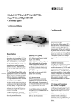
PageWriter 200/300pi M1771A/1770A Cardiograph
About This Edition
WARNING
CAUTION
Edition 2
Printed in the USA
Publication number M1770-91930
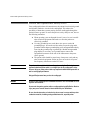
As with electronic equipment, Radio
Frequency (RF) interference between
the cardiograph and any existing RF
transmitting or receiving equipment at
the installation site, including
electrosurgical equipment, should be
evaluated carefully and any limitations
noted before the equipment is placed in
service.
Use of accessories other than those
recommended by Agilent Technologies
may compromise product performance.
The information in this guide applies to
the M1771/M1770 PageWriter 200/
300pi Cardiograph. This information is
subject to change without notice.
Agilent Technologies shall not be liable
for errors contained herein or for
incidental or consequential damages in
connection with the furnishing,
performance, or use of this material.
Edition History
Edition 1, August 1998
Edition 2, November 1999
Copyright
Copyright © 1999
Agilent Technologies, Inc.
3000 Minuteman Road
Andover, MA 01810-1099
USA
(978) 687-1501
This document may not be photocopied,
reproduced, or translated to another
language without prior written consent
of Agilent Technologies, Inc.
ii
Radio frequency generation from
electrosurgical equipment and close
proximity transmitters may seriously
degrade performance.
Like all electronic devices, this
cardiograph is susceptible to
electrostatic discharge (ESD).
Electrostatic discharge typically occurs
when electrostatic energy is transferred
to the patient, the electrodes, or the
cardiograph. ESD may result in ECG
artifact that may appear as narrow
spikes on the cardiograph display or on
the printed report. When ESD occurs,
the cardiograph’s ECG interpretation
may be inconsistent with the
physician’s interpretation.
Agilent Technologies assumes no
liability for failures resulting from RF
interference between Agilent medical
electronics and any radio frequency
generating equipment at levels
exceeding those established by
applicable standards.
THIS PRODUCT IS NOT INTENDED
FOR HOME USE.
IN THE U.S., FEDERAL LAW
RESTRICTS THIS DEVICE TO SALE
ON OR BY THE ORDER OF A
PHYSICIAN.
Medical Device Directive
The M1771A/M1770A PageWriter 200/
300pi Cardiograph complies with the
requirements of the Medical Device
Directive 93/42/EEC and carries the
0123 mark accordingly.
Authorized EU-representative:
Agilent Technologies Deutschland
GmbH
Herrenbergerstrasse 130
D-71034 Boeblingen
Germany
Fax: +49-7031-14-2346
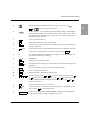
&RQYHQWLRQV
Conventions Used in This Manual
WARNING
Warning statements describe conditions or actions that can result in
personal injury or loss of life.
CAUTION
Caution statements describe conditions or actions that can result in
damage to the equipment or software.
NOTE
Notes contain additional information on cardiograph usage.
.H\
Represents keys on the key panel.
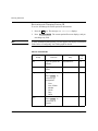
Safety Summary
Safety Symbols Marked on the Cardiograph
The following safety symbols are used on the cardiograph.
Caution - See operating instructions.
Meets IEC type CF leakage current requirements and is
defibrillator protected (Isolated ECG input).
Alternating current.
Equipotential (identifies independent protective earth
conductor to the cardiograph).
PageWriter 200/300pi M1771A/1770A Cardiograph
iii
&RQYHQWLRQV
Fuse.
Indicates power control for cardiograph.
Recycle.
Sealed Lead Acid Battery - Recycle or dispose of properly.
Hz
Indicates operating frequency in cycles per second.
Please see "Maintaining the Cardiograph", for further information
about operating your cardiograph safely.
Cardiograph Packaging Symbols
The following symbols appear on the packagin for the cardiograph:
Keep dry.
Temperature and relativey humidity
ranges.
Fragile.
Keep upright.
iv
Contents
6DIHW\6\PEROV0DUNHGRQWKH&DUGLRJUDSK LLL
*HWWLQJ$FTXDLQWHG
7KH.H\ERDUGDQG)URQW3DQHO $ERXW<RXU&DUGLRJUDSK 2SWLRQV 3DWLHQWDQG2SHUDWLRQDO6DIHW\1RWHV (OHFWURPDJQHWLF&RPSDWLELOLW\ 5HGXFLQJ(OHFWURPDJQHWLF,QWHUIHUHQFH 5HVWULFWLRQVIRU8VH $&DQG%DWWHU\2SHUDWLRQ 5HFRUGLQJDQ(&*
3UHSDULQJWKH3DWLHQW 1RWHVIRU&XVWRPHUV8VLQJ5HXVDEOH(OHFWURGHV 1RWHVIRU&XVWRPHU8VLQJ'LVSRVDEOH7DE(OHFWURGHV 8QGHUVWDQGLQJ:KHQD6LJQDOLV$FTXLUHG 3HUIRUPLQJD6WDW(&*%\SDVVLQJ3DWLHQW,'(QWU\ &KHFNLQJ6LJQDO4XDOLW\ (QWHULQJ3DWLHQW,' 5HYLHZLQJDQG&KDQJLQJ3DWLHQW,' 5HFRUGLQJD0DQXDO(&* 5HVWRULQJWKH(&*7UDFH$IWHU'HILEULOODWLRQRU5HFRQQHFWLQJ/HDGV 5HFRUGLQJDQ$XWR(&* 0DNLQJ&RSLHVRI$XWR(&*V 8QGHUVWDQGLQJWKH3ULQWHG5HSRUW &KRRVLQJD5HSRUW)RUPDW &KDQJLQJWKH5HSRUW)RUPDW $XWR5HSRUW)RUPDWV 0DQXDO5HSRUW)RUPDWV 7KH$XWR(&*5HSRUW $XWR5HSRUW([DPSOHV i
Contents
0DQXDO5HSRUW([DPSOHV 8QGHUVWDQGLQJ(&*$QDO\VLVDQGWKH3UHGLFWLYH,QVWUXPHQWV$SSOLFDWLRQV
8QGHUVWDQGLQJWKH(&*$QDO\VLV3URJUDP +RZWKH3DJH:ULWHUSL0HDVXUHV(&*V :DYHIRUP5HFRJQLWLRQ &RPSUHKHQVLYH0HDVXUHPHQWV *URXS0HDVXUHPHQWV /HDG0HDVXUHPHQWV $WULDO5K\WKP$QDO\VLV *OREDO0HDVXUHPHQWV $[LV0HDVXUHPHQWV $XWRPDWLFDOO\0HDVXULQJDQG,QWHUSUHWLQJ(&*V 8QGHUVWDQGLQJWKH([WHQGHG0HDVXUHPHQWV5HSRUW 7KH([WHQGHG0HDVXUHPHQWV5HSRUW 0RUSKRORJ\$QDO\VLV 5K\WKP$QDO\VLV 8QGHUVWDQGLQJWKH3DJH:ULWHUSL3UHGLFWLYH,QVWUXPHQW$SSOLFDWLRQV ,QGLFDWLRQVIRU8VH 8QGHUVWDQGLQJ73,9DULDEOHV 8QGHUVWDQGLQJ$&,7,3,9DULDEOHV 8VLQJWKH73,DQG$&,7,3,$SSOLFDWLRQV $QDO\]LQJDQ(&*ZLWKWKH3UHGLFWLYH,QVWUXPHQWV 2EWDLQLQJ$OWHUQDWH5HSRUWV (&*6WRUDJH2SWLRQV$RU6WUHVV:ULWHU
$GYDQWDJHVRI6WRUDJH 6WRULQJ(&*V 0DQDJLQJ6WRUHG(&*V 6HOHFWLQJ6WRUHG(&*V 3ULQWLQJ6WRUHG(&*V 'HOHWLQJ6WRUHG(&*V (GLWLQJ3DWLHQW,'IRU6WRUHG(&*V 3ULQWLQJWKH/RJRI(&*V7DNHQRUWKH/RJRI(&*V6WRUHG ii
Contents
7UDQVPLWWLQJ)D[LQJDQG5HFHLYLQJ$XWR(&*V2SWLRQV$RU6WUHVV:ULWHU
RQO\
7UDQVPLWWLQJ(&*V &KDQJLQJD7HOHSKRQH'LUHFWRU\(QWU\ 5HFHLYLQJ(&*V 5HFHLYLQJ(&*VVHQWE\D5HPRWH'HYLFH 5HTXHVWLQJ(&*VIURPD5HPRWH'HYLFH 7URXEOHVKRRWLQJ
&KHFNLQJ(&*7HFKQLTXH ,GHQWLI\LQJ(&*3UREOHPV ,IWKH5HFRUGLQJ:RQªW6WDUW ,IWKH&DUGLRJUDSK:RQªW3ULQWD0DQXDO5HSRUW (UURU0HVVDJHV ,GHQWLI\LQJ6WRUDJH3UREOHPV2SWLRQV$RU6WUHVV:ULWHURQO\ ,GHQWLI\LQJ7UDQVPLVVLRQ3UREOHPV2SWLRQV$RU6WUHVV:ULWHURQO\ 0DLQWDLQLQJWKH&DUGLRJUDSK
&DUHDQG&OHDQLQJ &OHDQLQJWKH&DUGLRJUDSK &OHDQLQJWKH(OHFWURGHVDQG&DEOHV &OHDQLQJWKH'LJLWDO$UUD\3ULQWKHDGDQG3DSHU6HQVRU /RDGLQJWKH3DSHU 6WRULQJWKH3DSHUDQG3DWLHQW(&*5HFRUGV &DULQJIRUWKH%DWWHU\ 6WRULQJWKH%DWWHU\ 5HSODFLQJWKH)XVHV 7RUHSODFHWKH$&IXVHV 6XSSOLHV &DOOLQJIRU6HUYLFH 8QLWHG6WDWHVRI$PHULFD &DQDGD 2WKHU,QWHUQDWLRQDO$UHDV iii
Contents
6HWWLQJ8S<RXU&DUGLRJUDSK
&KHFNLQJWKH9ROWDJH6HWWLQJ $
7KH%DWWHU\ $
,QVWDOOLQJWKH%DWWHU\$
&RQQHFWLQJWKH&DEOHV $
/RDGLQJ3DSHU $
6HWWLQJWKH.H\ERDUG0RGH $
6HWWLQJWKH&DUGLRJUDSK/RFDWLRQDQG,'&RGHV
2SWLRQV$RU6WUHVV:ULWHURQO\$
&RQQHFWLQJWKH'LUHFW7UDQVPLVVLRQ&DEOH
2SWLRQV$RU6WUHVV:ULWHURQO\$
7UDQVPLWWLQJRU)D[LQJ(&*VE\0RGHP
2SWLRQV$RU6WUHVV:ULWHURQO\$
6HWWLQJ8SWKH7HOHSKRQH'LUHFWRU\2SWLRQV$RU6WUHVV:ULWHURQO\$
6HWWLQJ8S3UHGLFWLYH,QVWUXPHQWV $
&RQILJXULQJ<RXU&DUGLRJUDSK
7KH&RQILJXUDWLRQ0HQX%
1DYLJDWLQJWKH&RQILJXUDWLRQ0HQXV %
3DWLHQW,'(QWULHV %
3RZHU2Q5HSRUW)LHOGV %
)LOWHUV %
0LVFHOODQHRXV5HSRUW)LHOGV %
6HWWLQJ'DWHDQG7LPH%
3ULQWLQJWKH&RQILJXUDWLRQ%
$GMXVWLQJ'LVSOD\6FUHHQ&RQWUDVW%
6HWXS7UDQVPLVVLRQ2SWLRQV$RU6WUHVV:ULWHURQO\ %
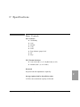
6SHFLILFDWLRQV
%DVLF&RQWUROV&
)UHTXHQF\DQG,PSXOVH5HVSRQVH&
,QVWUXPHQW7HVW&
3DWLHQW6DIHW\ &
iv
Contents
3RZHUDQG(QYLURQPHQW&
v
Contents
vi
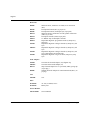
1 Getting Acquainted
1
This chapter describes to the new user the many features of the PageWriter
200/300pi cardiograph, patient and operational safety, A/C, and battery
operation. The user should become familiar with this material, especially the
safety information, prior to using the cardiograph.
NOTE
See Setting Up Your Cardiograph, for information on checking the voltage
switch setting, installing the battery, connecting the cables, and loading paper.
Each of these tasks must be done prior to operating the cardiograph for the
first time.
If accurate ST segment contours are required for ECGs recorded in Manual
mode, do not use the 0.5 Hz baseline wander filter. This filter suppresses
baseline wander to the extent that it may alter the ST segment. Instead,
configure your cardiograph to use the 0.15 Hz or 0.05 Hz baseline wander
filter. Regardless of the filter used, the rhythm characteristics of the ECG are
accurately recorded.
PageWriter 200/300pi M1771A/1770A Cardiograph
1-1
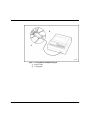
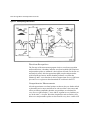
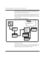
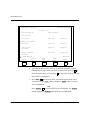
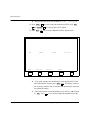
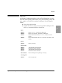
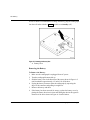
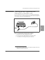
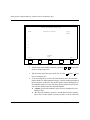
Figure 1-1: The PageWriter 200/300pi Cardiograph
A. Patient Cable
B. Cardiograph
1-2
Getting Acquainted
1
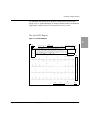
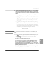
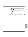
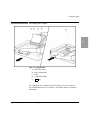
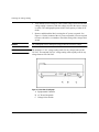
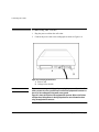
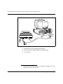
Figure 1-2: Bottom View of Cardiograph
A.
B.
C.
AC Fuse Holders with fuse replacement information
Mounting Point for Optional M1705B Cart
(Mounting screw included with cart)
Battery Door with battery replacement information
PageWriter 200/300pi M1771A/1770A Cardiograph
1-3
The Keyboard and Front Panel
The Keyboard and Front Panel
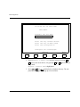
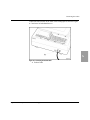
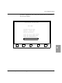
Figure 1-3: The Keyboard and Front Panel of the Cardiograph
1-4
Getting Acquainted
The Keyboard and Front Panel
$
Displays the configuration menu, unless an ECG report is in-process. Use
Stop , or
Exit ,
%
softkey
These five keys (F1 – F5), located directly beneath the display window, perform different
functions at different times. They are called “softkeys.” When a softkey is active, a label
describing its function is displayed above it on the screen. Press the key to perform the
function displayed on the screen.
&
Shift
Used to enter shifted characters.
'
ID
Allows patient identification entry, review, and edit.
(
Filter
Turns filters on and off. The filter or filters controlled by this key are selected during cardiograph configuration.
)
Shift ²&KDU
Enters the upper case letters and punctuation marks shown above the number keys when
you press the corresponding letter or number key while pressing the
*
$&
Shift key.
This indicator is lighted when the power cord is plugged into an active wall outlet. This
also indicates that the battery is charging.
+
,
The Enter key.
This key starts an Auto ECG recording.
-
Auto
Manual
.
Stop
Halts any cardiograph activity and restores the normal ECG display.
/
Copy
Prints a copy of the last Auto ECG.
0
Page
Advances the paper to the beginning of the next page.
1
Starts a Manual ECG recording. Also restores the ECG trace during a Manual report after
defibrillation.
To view lead groups, use the
or
keys to move to the next lead group, and the
or
keys to move to the previous lead group. The
or
keys move the cursor
down on configuration displays and patient ID information screens. The
keys move the cursor up.
2
3
Alt
Alt –&KDU
On/Standby
and
Used to enter alternate characters. (See item P.)
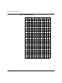
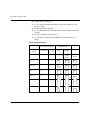
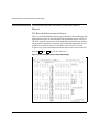
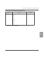
To enter the characters shown above the letter keys (see Table 1-1 for language-specific
keys), press the
4
1
to return to the normal ECG display.
Alt key with the desired letter.
Switches the cardiograph between On and Standby. Standby means the cardiograph is
off, but charging the battery, when it is plugged in to AC power.
PageWriter 200/300pi M1771A/1770A Cardiograph
1-5
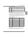
The Keyboard and Front Panel
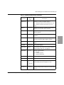
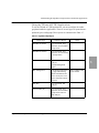
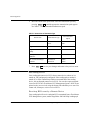
Table 1-1: Characters by Language
Key
English
French
German
DOW $/7 DOW $/7 DOW
$/7
D
Dutch
DOW
$/7 DOW
$/7
Spanish
DOW
$/7
j
j
l
b
l
b
j
j
i
$
E
`
`
`
`
`
`
F
#
_
#
_
#
_
#
_
#
_
#
_
G
!
!
! !
!
!
!
!
!
!
!
!
r
r
s
s
p
e
I
"
"
"
"
"
"
"
"
"
"
"
"
J
?
?
?
?
?
?
K
“
“
“
“
“
“
“
“
“
“
“
“
v
v
u
u
t
t
’
’
’
’
’
’
’
’
’
’
’
’
q
q
p
e
x
f
H
L
M
N
O
P
a
@
a
@
a
@
a
@
a
@
a
@
Q
>
>
>
>
>
>
R
{
{
|
g
|
g
z
z
y
y
S
o
d
ß
ß
ƒ
k
k
~
T
V
X
Y
[
h
h
^
A
^
A
^
A
^
º
º
^
A
p
e
q
q
\
]
A
Z
1-6
Italian
º
º
h
Getting Acquainted
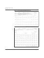
The Keyboard and Front Panel
Key
Norwegian
Swedish
DOW
$/7
DOW
$/7
D
n
c
l
b
E
`
`
Finnish
DOW
$/7
`
F
#
_
#
_
#
_
G
!
!
!
!
!
!
H
I
"
"
"
"
"
Polish
DOW
`
$/7
Portuguese
DOW
$/7
j
!
!
k
Ç
"
"
Key
Russian
DOW
1
$/7
`
"
"
"
J
K
“
“
“
“
“
“
“
“
’
’
’
’
’
’
‘
‘
P
a
@
a
@
a
@
Q
>
>
>
R
¡
|
g
|
g
~
Ô
m
®
r
È
{
Ñ
r
È
}
¯
i
É
L
M
N
O
S
“
T
n
c
n
“
c
U
V
W
X
Y
h
h
!
!
^
^
A
^
A
^
A
^
å
ä
Z
[
\
]
PageWriter 200/300pi M1771A/1770A Cardiograph
1-7
About Your Cardiograph
About Your Cardiograph
Your PageWriter 200/300pi cardiograph:
l
l
l
l
l
l
l
Acquires 12 leads simultaneously.
Allows you to check lead quality on the preview screen before
printing the ECG.
Provides selectable formats (Auto and Manual).
Reports measurements of the ECG.
Operates on a rechargeable battery. AC power charges the battery.
Has a digital array printer with continuous-feed paper.
Has a 200 sheet Z-fold paper capacity.
In addition to the features listed above, the PageWriter 300pi cardiograph can
analyze and interpret the ECG. The PageWriter 300pi also includes Predictive
Instrument applications that detect Acute Myocardial Infarction and Acute
Cardiac Ischemia, as well as calculate predicted outcome with and without
thrombolytic therapy.
Accessories
Your cardiograph was shipped with one of the following three accessory sets,
according to your geographic option:
No Electrodes Accessory Set — Options: ABB, ABD, ABE, ABF, ABH,
ABS, ABU, ABX, ABZ, AKD, ACB, AC4, AB9, ABN
l
l
l
l
l
l
l
Battery assembly
Power cord
Patient Cable
1 package of paper
PageWriter 200/300pi User’s Guide
Using the HP PageWriter 200/200i Cardiograph operator training
video (also applicable to the PageWriter 300pi)
Hewlett-Packard Interpretive Cardiograph Physician’s Guide
For electrodes, contact your local Agilent Technologies Sales Office or your
authorized Agilent Technologies Dealer or Distributor.
1-8
Getting Acquainted
About Your Cardiograph
Reusable Electrodes Accessory Set — Options: ABG, ABK, ABM, AB2,
AB4, AKV, ABK, AKM, ACQ, AC6, ACJ
l
l
l
l
l
l
l
l
l
Battery assembly
Power cord
Patient Cable
1 package of paper
6 Welsh bulb electrodes
4 limb plate electrodes and straps
PageWriter 200/300pi User’s Guide
Using the HP PageWriter 200/200i Cardiograph operator training
video (also applicable to the PageWriter 300pi)
Hewlett-Packard Interpretive Cardiograph Physician’s Guide
1
Disposable Electrodes Accessory Set — Options: ABA, ABC
l
l
l
l
l
l
l
l
l
Battery assembly
Power cord
Patient Cable
1 package of paper
Disposable electrode starter set
Tab electrode adapters
PageWriter 200/300pi User’s Guide
Using the HP PageWriter 200/200i Cardiograph operator training
video (also applicable to the PageWriter 300pi)
Hewlett-Packard Interpretive Cardiograph Physician’s Guide
Options
Your PageWriter 200/300pi cardiograph can store and transmit ECGs if you
purchased Options #A05 or StressWriter. See ECG Storage (Options #A05 or
StressWriter), for information about storing, retrieving and editing ECGs. See
Transmitting, Faxing, and Receiving Auto ECGs (Options #A05 or
StressWriter only), for information about sending ECGs to other PageWriter
cardiographs or the TraceMaster ECG Management system.
PageWriter 200/300pi M1771A/1770A Cardiograph
1-9
Patient and Operational Safety Notes
Patient and Operational Safety Notes
Your cardiograph isolates all connections to the patient from electrical ground
and all other conductive circuits in the cardiograph. This reduces the
possibility of hazardous currents passing from the cardiograph through the
patient’s heart to ground. To ensure the patient’s safety and your own, observe
the following reminders:
l
l
l
WARNING
When operating your cardiograph from AC power, be sure it and all
other electrical equipment connected to or near the patient are
effectively grounded.
Use only grounded power cords (three-wire power cords with
grounded plugs). Also make sure the outlet accepts the plug and is
grounded. Never adapt a grounded plug to fit an ungrounded outlet by
removing the ground prong or ground clip. Should an ungrounded
plug adapter be necessary, use a ground strap to connect the
equipotential connector at the rear of the instrument to the power
source ground.
The patient cable should be routed away from power cords and any
other electrical equipment. Failure to do so can result in AC power
line frequency interference on the ECG trace.
The patient cable supplied with this cardiograph, or an Agilent Technologies
approved substitute patient cable, is an integral part of the cardiograph’s safety
features. Using any other patient cable may compromise defibrillation protection as
well as cardiograph performance.
Only qualified personnel may service the cardiograph.
WARNING
Do not use this cardiograph near flammable anesthetics. It is not intended for use in
explosive environments.
Do not touch the patient, patient cable or cardiograph during defibrillation. Death or
injury may occur from the electrical shock delivered by the defibrillator.
Be sure that the electrodes or lead wire tips do not come in contact with any other
conductive materials, including earth-grounded materials, especially when
1-10
Getting Acquainted
Electromagnetic Compatibility
connecting or disconnecting electrodes to/from a patient.
The use of multiple instruments connected to the same patient may pose a safety
hazard due to the summation of leakage currents from each instrument. Any
combination of instruments should be evaluated by local safety personnel before
being put into service.
Do not pull on the paper while a report is being printed. This can cause distortion of
the waveform and can lead to potential misdiagnosis.
WARNING
(#A05 or StressWriter Options only) Equipment connected to the cardiograph’s RS232 connector can cause ground leakage currents exceeding the maximum specified
in IEC601-1 safety standards.
Do not connect any equipment to the RS-232 connector during cardiograph
operation unless you can verify that the leakage current is within the specified
limits.
CAUTION
Do not block the ventilation slots. Lack of ventilation may cause the
cardiograph to overheat, resulting in failure of internal electronic components.
NOTE
The Agilent Technologies warranty is only assured if you use Agilent
Technologies approved accessories and replacement parts. See Maintaining
the Cardiograph for more information.
Electromagnetic Compatibility
When using the PageWriter 200/300pi, electromagnetic compatibility with
surrounding devices should be assessed.
A medical device can either generate or receive electromagnetic interference.
Testing for electromagnetic compatibility (EMC) of the PageWriter 200/300pi
cardiograph has been performed according to IEC 601-1-2. This IEC standard
has been adopted in Europe as the European Norm (EN 60601-1-2).
This EMC standard describes tests for both emitted and received interference.
Emission tests deal with interference generated by the device being tested.
PageWriter 200/300pi M1771A/1770A Cardiograph
1-11
1
Reducing Electromagnetic Interference
Tests for the 200/300pi cardiographs show they do not emit interference that
exceeds the IEC 601-1-2 limits.
Reducing Electromagnetic Interference
The M1770/M1771 PageWriter 200/300pi cardiographs are susceptible to
interference from other RF energy sources and continuous, repetitive, power
line bursts. Examples of other sources of RF interference are medical devices,
cellular products, information technology equipment and radio/television
transmission. Should interference be encountered, as demonstrated by artifact
on the ECG, attempt to locate the source. Assess:
l
l
l
Is the interference intermittent or constant?
Does the interference occur only in certain locations?
Does the interference occur only when in close proximity to certain
medical devices?
Once the source is located, attempt to attenuate the EMC coupling path by
distancing the cardiograph from the source as much as possible. If assistance
is needed, call your local Agilent Technologies service representative.
Restrictions for Use
Artifact on the ECG caused by electromagnetic interference should be
evaluated by a physician or physician authorized personnel to determine if it
will negatively impact patient diagnosis or treatment.
AC and Battery Operation
The battery must be installed for proper operation of the cardiograph—even if
the cardiograph is plugged into AC power, it cannot print an ECG report
without the battery. For information about replacing or installing the battery,
refer to Setting Up Your Cardiograph.
The following is a list of AC and battery operating information:
l
1-12
A fully charged battery (without AC power) will print approximately
40 Auto ECGs, or approximately 40 minutes of continuous Manual
ECG information.
Getting Acquainted
AC and Battery Operation
l
l
l
l
l
NOTE
If the cardiograph is turned on while the battery is being charged, these
charging times are doubled (10 minutes for an Auto ECG and 20 minutes for a
1-minute Manual ECG).
l
NOTE
The Low Battery message on the display indicates the battery
needs to be charged.
From the time the Low Battery message is first displayed to when
the cardiograph automatically is turned to Standby (off), there is
typically enough reserve battery capacity to record two Auto ECGs or
2-minutes of Manual ECG data. A weak or faulty battery will reduce
this time.
The flashing Low Battery message indicates that the cardiograph
will turn itself off in one minute unless it is plugged into AC power.
A discharged battery requires at least 5 minutes charging time, with
the cardiograph in Standby (off), before printing an Auto ECG.
A discharged battery requires at least 10 minutes charging time, with
the cardiograph in Standby (off), before printing a 1-minute Manual
ECG.
The PageWriter 200/300pi cardiograph has a battery-saving feature: it
will turn itself to Standby (off) after 30 minutes of instrument
inactivity. This prevents the cardiograph from being accidentally left
on for extended periods of time.
This feature is not active if all the limb electrodes are connected to a patient
or if the cardiograph is plugged into AC power.
l
l
l
l
A new battery or a battery that has been stored for an extended period
of time requires charging (with the cardiograph in Standby (off)) for
16 hours in order to guarantee a full charge.
The battery, if installed, is being charged any time the AC light is on.
A fully depleted battery will charge to 90% of full capacity in 7 hours,
and 100% capacity in 16 hours, as long as the cardiograph is in
Standby (off) for the entire time.
When the cardiograph is not in use, it should be connected to AC
power and left in Standby (off). This will maintain a full battery
charge and prolong battery life.
PageWriter 200/300pi M1771A/1770A Cardiograph
1-13
1
AC and Battery Operation
NOTE
The cardiograph’s battery charging circuit delivers less power than the
cardiograph uses while printing an ECG. It is possible to run down the battery,
even when the cardiograph is plugged into AC power, if the printer is being
heavily used.
1-14
Getting Acquainted
2 Recording an ECG
This chapter describes how to:
l
l
l
l
l
l
prepare the patient for an ECG
check the signal quality of the patient leads
enter patient ID and printed report information
record an ECG
change the report format
understand the printed report
2
Samples of the different Manual and Auto ECG formats are also shown.
NOTE
If the cardiograph has not been setup, refer to Setting Up Your Cardiograph,
for instructions.
If your cardiograph is already configured, you can record an ECG by
performing the following steps and procedures. (If you need to configure your
cardiograph or check settings, refer to Configuring Your Cardiograph.)
1. If the cardiograph is not On, press 2Q6WDQGE\ .
2. Prepare the patient and apply the electrodes, as described in the next
section, “Preparing the Patient”.
3. Check the signal quality on all leads, as described in “Checking Signal
Quality” , later in this chapter.
4. Enter patient ID information, if necessary. This is described in “Entering
Patient ID” , later in this chapter.
5. Press $XWR to record a 12-lead ECG, or press 0DQXDO to record a rhythm
report.
The rest of this chapter discusses the details of setting up and recording ECGs.
PageWriter 200/300pi M1771A/1770A Cardiograph
2-1
Preparing the Patient
Preparing the Patient
For electrode placement information, refer to the diagram on the top of your
cardiograph.
NOTE
Proper patient preparation and electrode placement are the most important
elements in producing a high quality ECG trace.
Prepare the patient by performing the following steps.
1. Reassure and relax the patient. A calm and quiet patient produces the best
ECGs.
2. Make sure the electrode site is not covered by hair or clothing.
3. Gently clean and abrade the surface of the skin with dry gauze.
4. Place electrodes on patient. See the following notes regarding your type
of electrodes.
5. Attach each lead wire to the correct electrode.
6. The upper-left corner of the screen displays the electrodes that are not
placed firmly on the patient and/or the lead wires that are not attached
securely to the electrodes. (See Table 2-1.) This is an indication of “leads
off”. Correct the attachment of any lead/electrode pair that appears on the
screen.
NOTE
2-2
The patient cable should be routed away from power cords and any other
electrical equipment. Failure to do so can result in AC line frequency
interference on the ECG trace.
Recording an ECG
Preparing the Patient
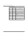
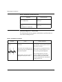
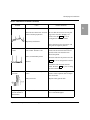
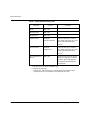
Table 2-1: Leads Off Labels
Designator
(AHA/IEC)
Meaning
RL/N
Right leg electrode not connected or only right leg electrode is
connected and all other limb electrodes are not connected.
RA/R
Right arm electrode is not connected.
LA/L
Left arm electrode is not connected.
LL/F
Left leg electrode is not connected.
V1...V6/
C1...C6
One or more chest electrodes are not connected. For example,
V2 means the V2 electrode is not connected.
2
Notes for Customers Using Reusable Electrodes
Each electrode must be attached securely. Straps must neither slide nor be so
tight as to cause discomfort.
The electrode paste, gel, or creme must cover an area the size of the electrode,
but must not extend beyond it, especially on the chest.
Notes for Customer Using Disposable Tab Electrodes
Disposable electrodes have conductive material on the adhesive side only.
The electrode tab must be placed between the jaws of the electrode adapter
clip, and remain flat. Do not attempt to place the jaws of the electrode adapter
so close to the circular part of the electrode that the tab of the electrode is
bent, or contact is made with the conductive gel. Gently tug on the electrode
adapter to ensure that the electrode adapter is properly placed on the
electrode.
Good and accurate placement on the first attempt should be your goal for each
electrode. Each time an electrode is lifted off the skin and attached again, the
adhesive gel becomes weaker and less effective.
NOTE
Never mix reusable and disposable electrodes on the same patient.
PageWriter 200/300pi M1771A/1770A Cardiograph
2-3
Understanding When a Signal is Acquired
Understanding When a Signal is Acquired
Your PageWriter 200/300pi cardiograph attempts to acquire a good signal for
an Auto report before you press the $XWR key. This is called pre-acquisition.
Pre-acquisition is activated when the cardiograph is turned on and remains
active until an Auto report begins to print. Pre-acquisition is also suspended
whenever an electrode is disconnected.
Pre-acquisition is reactivated when a patient ID is entered or edited, or when a
Manual report is finished printing.
When Pre-acquisition is active, it is important for the patient to stay still and
relaxed. This will help ensure a good signal is captured prior to printing an
Auto report.
NOTE
Pre-acquisition is not used for Manual ECG reports.
Performing a Stat ECG (Bypassing Patient ID
Entry)
Perform the following step when an ECG is needed quickly.
1. If the cardiograph is not On, press 2Q6WDQGE\ .
2. Prepare the patient and apply the electrodes.
3. Do one of the following:
A. Press 0DQXDO twice for a Manual ECG report.
B. Press $XWR twice for an Auto ECG report.
NOTE
Reports printed by following the above steps will use the last patient
identification information even if powered off in between. Be sure the patient
ID data on the report matches the patient.
NOTE
Signals seen on the screen can only be captured for an Auto report when Preacquisition is active. See “Understanding When a Signal is Acquired” for
more information on Pre-acquisition.
2-4
Recording an ECG
Checking Signal Quality
Checking Signal Quality
You can produce better ECGs by previewing the lead traces on the screen
before you record and print the ECG. By observing the traces and adjusting
the leads accordingly, you can make the best possible ECG recording.
The screen displays the output from the selected three leads whenever the
cardiograph is on.
The leads are displayed in five groups of three leads each. The groups are
listed below:
2
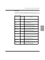
Table 2-2: Lead Groups
Group
Leads Displayed
Group 1
I, II, III
Group 2
aVR, aVL, aVF
Group 3
V1, V2, V3
Group 4
V4, V5, V6
Group 5
Custom 3
l
To select which three leads to display on the screen, press the
or
key, or the 6SDFH bar, to display the next lead group, or press the
l
l
or
key to display the previous lead group.
Before you connect the electrodes, each lead displays on the screen as
a dotted line, indicating that at least one of the electrodes associated
with the lead is not connected. The dotted line is known as a “leads
off” trace. Use the leads off labels (see Table 2-1) to determine which
leads are off.
As you connect the electrodes to the patient, the lead waveforms are
displayed on the screen.
PageWriter 200/300pi M1771A/1770A Cardiograph
2-5
Entering Patient ID
NOTE
The ECG traces are updated by the erase bar that moves across the screen.
Entering Patient ID
Entering patient ID information is not required to record an ECG. Note that
for the PageWriter 300pi, some ID fields affect the interpretation of Auto
ECGs and this ID information should therefore be entered. See
“Understanding ECG Analysis and the Predictive Instruments Applications”
for more information.
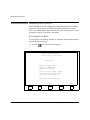
NOTE
If the cardiograph is configured to record no ID information, pressing ,'
displays the following message:
ID entry has been disabled
Change your configuration to
enter ID data.
Press any key to continue.
The following steps detail one of two methods of entering patient ID
information. See “Recording an Auto ECG” or “Recording a Manual ECG”
later in this chapter for the second method.
To enter patient identification, perform the following steps (these steps
assume all ID fields are enabled).
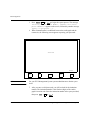
1. Press ,' . If there is an existing patient ID in the cardiograph, the
question New patient? is displayed. If not, the patient ID entry screen
is displayed. You can press 6WRS at any time to return to the ECG display.
A. If you press Yes, Enter New ID to answer the New patient?
query, the existing patient ID information is cleared and the patient ID
entry screen is displayed.
2-6
Recording an ECG
Entering Patient ID
B. If you press No, Edit Old ID to answer the New patient? query,
the existing patient ID information is displayed for you to review or
change, if necessary.
2. Type the patient ID number and press
requests the patient’s name.
,
, or
. The next line
3. Type the patient’s name and press the
,
, or
. The next line
requests the patient’s age. It also allows you to change the age designation
(Years, Year of Birth, Months, Weeks, Days, or Hours).
4. Type the patient’s age. Press Change until the screen displays the age
designation you want to use. Press
or
.
There are more patient ID fields into which you can enter patient information.
All of the patient information fields are shown in Table 2-3. Note that some
(or all) of these fields may be inactive for your configuration.
Each time you press the
or
, the information you entered is recorded
and the cursor moves down to the next ID field. To return to a previous field,
move the cursor up by pressing
or
.
To change or erase data you have entered, simply type over the existing data,
or use the %DFN key to delete the character to the left of the cursor or press
Erase , if available.
You can stop entering patient ID information at any time by pressing Exit
(or 6WRS ). This saves all the field entries in the patient ID record, including
the information you just entered.
NOTE
To start recording an ECG more quickly, you can press 0DQXDO or $XWR
instead of Exit or 6WRS . This saves all the patient ID information you just
entered and starts an ECG recording all at the same time.
PageWriter 200/300pi M1771A/1770A Cardiograph
2-7
2
Entering Patient ID
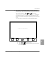
Reviewing and Changing Patient ID
To review and change the current patient ID information:
1. Press the ,'
key. The message New Patient? displays.
2. Press No, Edit Old ID . The current patient ID screen displays, and you
can change any field.
NOTE
To enter information more quickly, you can suppress the display of unused ID
fields. Refer to Configuring Your Cardiograph for details.
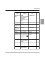
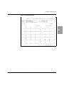
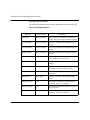
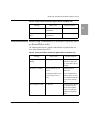
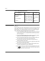
Table 2-3: Patient ID Fields
Prompt
Comments
Entry
# of
char.
ID:
Type the patient ID
number.
Alphanumeric
16
Name:
Type the patient
name.
Alphanumeric
30
Age:
Type the patient age.
Numeric
4
Press Change to
select the age
designation:
Years
Year of Birth
Months
Weeks
Days
Hours
Sex:
2-8
Press Change to
select Male or
Female.
Recording an ECG
Entering Patient ID
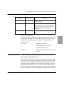
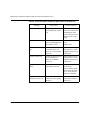
Table 2-3: Patient ID Fields
Prompt
Comments
Entry
# of
char.
Chest/LA pain
entry?
Blank
Yes, Chief Complaint
Yes, Secondary
Complaint
No Chest/Left Arm
Pain
3 character field
Acute Ischemic
Sx time Entry?
Type the time in
minutes.
3 character field
History
Diabetes Entry?
Yes or No
3 character field
History
Hypertension
Entry?
Yes or No
3 character field
Height:
Type the height.
Numeric
3
Weight:
Type the weight.
Numeric
3
Blood Pressure:
Type the systolic
value, then press
Numeric
3
2
.
Type the
diastolic value.
Operator:
Type the cardiograph
operator’s initials or
number.
Alphanumeric
4
Department:
Type the department
number where the
ECG is recorded.
Alphanumeric
8
Room:
Type the patient room
name or number.
Alphanumeric
8
PageWriter 200/300pi M1771A/1770A Cardiograph
2-9
Recording a Manual ECG
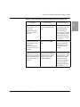
Table 2-3: Patient ID Fields
Prompt
Comments
# of
char.
Entry
Requested by:
Type name or number
of the person
requesting the ECG.
Alphanumeric
16
Custom Field
One:
This label can be
configured as needed.
See Table B-1.
Alphanumeric
16
Custom Field
Two:
This label can be
configured as needed.
See Table B-1.
Alphanumeric
16
Set ECG Mgmt
Priority to Stat?
Yes or No
Setup ID entry for
ECG management
system priority to
indicate a ‘STAT’
ECG. Only applies
to cardiographs with
storage and
transmission.
3
Recording a Manual ECG
To record a Manual ECG, perform the following steps.
1. If the cardiograph is not On, press 2Q6WDQGE\ .
2. Prepare the patient and apply the electrodes.
3. Check the signal quality on all leads.
4. Enter patient ID information, if necessary.
5. Press 0DQXDO on the front panel.
l
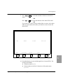
2-10
If you did not enter a patient ID in the above step and have not
entered a patient ID since turning on the cardiograph, the message No
Recording an ECG
Recording a Manual ECG
ID, Continue? is displayed. Press Yes to record the ECG
without a patient ID. Press No, Enter ID to enter patient ID information.
l
If you did not enter a patient ID in the above step but have entered
patient ID information since the cardiograph was turned on, the
question
Continue using Old ID? is displayed.
If you have entered a patient identification number and want to take
more ECGs from the same patient, press Yes .
If you are recording an ECG from another patient, press No, Edit Old ID
or No, Enter New ID .
NOTE
Your cardiograph automatically checks for a patient ID each time you start an
ECG, unless it is configured for no patient ID information. To bypass this
check and use the last entered patient ID, press 0DQXDO a second time.
6. The cardiograph prints the ECG continuously until you press the 6WRS
key.
NOTE
If accurate ECG ST contours are required for ECGs recorded in Manual
mode, do not use the 0.5 Hz baseline wander filter. This filter suppresses
baseline wander to the extent that it may alter the ST segment. Instead,
configure your cardiograph to use the 0.15 Hz or 0.05 Hz baseline wander
filter. Regardless of the filter used, the rhythm characteristics of the ECG are
accurately recorded. Refer to Configuring Your Cardiograph for details on
configuring filters.
The leads recorded by the manual ECG, the chart speed, sensitivity, and filter
status can be changed at any time, even while a manual ECG is running. To
change these settings simply select Format , Leads , Speed , Size , or )LOWHU
keys, as appropriate. Note, however, that the ECG printer will pause as the
cardiograph changes its recording status.
l
The Format key sequence is: 3 ⇒ 6 ⇒ 12 ⇒ 3 ...
PageWriter 200/300pi M1771A/1770A Cardiograph
2-11
2
Restoring the ECG Trace After Defibrillation or Reconnecting Leads
l
The Leads key sequence is:
3 lead manual - Custom ⇒ I II III ⇒ aVR, aVL, aVF ⇒ V1 V2 V3
⇒ V4 V5 V6 ⇒ Custom ...
6 lead manual - Custom Leads ⇒ Limb Leads ⇒ V1–V6 Leads ⇒
Custom Leads ...
l
The Speed key sequence is: 25 ⇒ 50 ⇒ 5 ⇒ 10 ⇒ 25 ... (numbers
indicate chart speed in mm/sec).
l
The Size key sequence is: 1.0 ⇒ 1.0 ½V ⇒ 2.0 ⇒ 2.0 ½V ⇒ 0.5 ⇒
0.5 ½V ⇒ 1.0 ...
l
The )LOWHU key sequence is an On/Off toggle. When )LOWHU is active,
Filter is displayed on the screen.
Restoring the ECG Trace After Defibrillation or
Reconnecting Leads
After application of a defibrillator pulse, reconnecting one or more leads, or
any other time the ECG signal is off-center during a Manual report, the trace
can be quickly restored by pressing the 0DQXDO key.
Recording an Auto ECG
To record an Auto ECG, perform the following steps.
1. If the cardiograph is not On, press 2Q6WDQGE\ .
2. Prepare the patient and apply the electrodes.
3. Check the signal quality on all leads.
4. Enter patient ID information, if necessary.
5. The leads recorded by the Auto ECG, the chart speed, sensitivity, and
filter status can be changed before the Auto ECG starts. To change these
settings simply select Format , Leads , Speed , Size , or )LOWHU keys, as
appropriate.
l
2-12
The Format key sequence is: 3x4 ⇒ 3x4 1R ⇒ 3x4 3R ⇒ 6x2 ⇒ 3x4
...
Recording an ECG
Recording an Auto ECG
l
The Leads key sequence is:
3x4 1R: I ⇒ ΙΙ ⇒ ΙΙΙ ⇒ aVR ⇒ aVL ⇒ aVF ⇒ V1 ⇒ V2 ⇒ V3 ⇒
V4 ⇒ V5 ⇒ V6 ⇒ I ...
3x4 3R: Custom Leads ⇒ Ι, ΙΙ, ΙΙΙ ⇒ aVR, aVL, aVF ⇒ V1, V2, V3
⇒ V4, V5, V6 ⇒ Custom Leads ...
l
The Speed key sequence is: 25 ⇒ 50 ⇒ 25 ...(numbers indicate chart
speed in mm/sec).
l
The Size key sequence is: 1.0 ⇒ 1.0 ½V ⇒ 2.0 ⇒ 2.0 ½V ⇒ 0.5 ⇒
0.5 ½V ⇒ 1.0 ...
l
The )LOWHU key sequence is an On/Off toggle. When )LOWHU is active,
Filter is displayed on the screen.
6. Press $XWR on the front panel.
l If you did not enter a patient ID in the above step and have not
entered a patient ID since turning on the cardiograph, the message No
ID, Continue? is displayed. Press Yes to record the ECG
without a patient ID. Press No, Enter ID to enter patient ID information.
l
If you did not enter a patient ID in the above step but have entered
patient ID information since the cardiograph was turned on, the
question Continue using Old ID? is displayed.
If you have entered a patient identification number and want to take
more ECGs from the same patient, press Yes .
If you are recording an ECG from another patient, press No, Edit Old ID
or No, Enter New ID .
NOTE
Your cardiograph automatically checks for a patient ID each time you start an
ECG, unless it is configured for no patient ID information. To bypass this
check and use the last entered patient ID information, press $XWR a second
time.
7. The status messages Acquiring ECG..., Processing...,
Analyzing... and Printing... are displayed.
PageWriter 200/300pi M1771A/1770A Cardiograph
2-13
2
Making Copies of Auto ECGs
Making Copies of Auto ECGs
If you require additional copies of an Auto ECG, you may print a copy of the
last ECG that was recorded. See Figures 2-1 through 2-6 for examples of the
report formats available.
To print a copy of your most recent Auto ECG, press the &RS\ key. The
message Printing... is displayed and the copy is printed.
To print a copy of the extended measurements report for the most recent ECG,
press the 6KLIW and &RS\ keys at the same time. The extended measurements
report summarizes the morphology and rhythm characteristics for the
individual lead waveforms and rhythm groups in the ECG. The PageWriter
300pi uses these measurements to suggest an interpretation. See Figure 3-3
and Figure 3-5 in “Understanding ECG Analysis and the Predictive
Instruments Applications” for examples of the extended measurements report.
NOTE
Unless you save the ECG, you must print an additional copy before the
cardiograph has been turned to Standby (off), before another ECG has been
acquired, before changing the ID, and before changing the cardiograph
configuration.
You may print copies of a stored ECG at any time. See Printing Stored ECGs
in ECG Storage (Options #A05 or StressWriter), for more information.
You may change the format and corresponding leads, and speed (25 or 50
mm/sec) prior to printing a copy of an ECG.
You can only print copies of Auto ECGs.
Copies of ECGs use the copy interpretation format specified when the
cardiograph was configured. See the section titled Miscellaneous Report
Fields in Configuring Your Cardiograph.
2-14
Recording an ECG
Understanding the Printed Report
Understanding the Printed Report
The PageWriter 200/300pi provides Auto, Manual, and Extended
Measurements reports. This section describes the Manual and Auto reports.
The Manual report features closely resemble those of the Auto report. The
Extended Measurements report is described in “Understanding ECG Analysis
and the Predictive Instruments Applications”.
Choosing a Report Format
2
An Auto report prints a one- or two-page summary of all 12 cardiograph
leads. (More pages may be needed to print additional interpretation
statements. See Table 2-4). A Manual report prints continuously until the
6WRS
key is pressed. The Auto and Manual report formats are available for
both standard and Cabrera leads. The Cabrera lead order is an alternative limb
lead order in which aVR is inverted and shown as -aVR. Lead order is aVL, I,
-aVR, II, aVF, III, V1 through V6. The Cabrera lead order makes it easier to
visualize waveform progression in the frontal plane.
Using the softkeys below the cardiograph’s display, the user can select the
desired report format and lead configuration. To change to a different report
format, see “Changing the Report Format” later in this section.
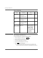
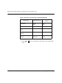
Table 2-4: Auto Report Length Configurations
Number of pages in Auto report
Model
At 25 mm/sec
At 50 mm/sec
300pi with
Interpretation off
1
2
300pi with
interpretation on
1 or more
2 or more
200
1
2
PageWriter 200/300pi M1771A/1770A Cardiograph
2-15
Choosing a Report Format
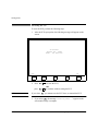
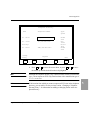
Changing the Report Format
To change the report format:
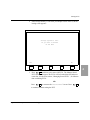
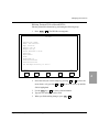
1. Press 6WRS . The bottom of the display will be similar to the one shown
below.
Auto
Report
3x4,3R
Format
I,II,III
Leads
25mm/s
Speed
1.0
Size
2. Press 5HSRUW to select between Auto or Manual report menus. Note that
the data displayed above the )RUPDW and /HDGV softkeys will change as
you switch between the Auto and Manual report formats.
3. Press )RUPDW to select the report presentation. The selections are:
l
l
Auto Formats: 3x4, 3x4 1R, 3x4 3R, 6x2
Manual Formats: 3, 6, 12
4. Press /HDG or /HDGV , if available for your format, to select the leads you
wish to record.
Auto Report Formats
12-lead Auto reports may be displayed in 3x4 or 6x2 formats. The 6x2 format
displays longer segments of waveform information than the 3x4 format.
Rhythm strips may be added to the 3x4 format to display longer ECG
segments from one (or three) leads. For the 3x4 1R and 3x4 3R formats, the
rhythm lead(s) may be configured to be any one (or three) of the 12 available
leads. Refer to Figures 2-1 through 2-6 for examples of these Auto report
formats.
Manual Report Formats
Manual ECGs run continuously, from the time you press 0DQXDO until you
press 6WRS . The cardiograph can be configured to display Manual reports
with either 3, 6, or 12 leads. Manual ECGs reflect the ECG waveform as it
occurs with a small delay.
2-16
Recording an ECG
Choosing a Report Format
Other lead groups can be selected while recording an ECG, and custom lead
groups can also be selected. (See Power-On Report Fields in Configuring
Your Cardiograph for information about setting up custom lead combinations
for Manual ECG reports.) Refer to Figures 2-7, 2-8, and 2-9 for examples of
these Manual report formats.
The following tables show the standard and default-custom lead
configurations.
Table 2-5: Manual Report Standard Formats
Number
of
Leads
Standard Lead Choices
2
Default Custom Lead
Choices
3
I, II, III
aVR, L, F (aVR, aVL, aVF)
V1, V2, V3
V4, V5, V6
II, aVF, V2
6
Limb (I, II, III, aVR, aVL, aVF)
V1–V6 (V1, V2, V3, V4, V5, V6)
II, aVF, V2, III, V1, I
12
I, II, III, aVR, aVl, aVF, V1, V2, V3,
V4, V5, V6
Table 2-6: Manual Report Cabrera Formats
Number
of
Leads
Standard Lead Choices
Default Custom Lead
Choices
3
aVL, I, -aVR
II, aVF, III
V1, V2, V3
V4, V5, V6
II, aVF, V2
6
Limb (aVL, I, -aVR, II, aVF, III)
V1–V6 (V1, V2, V3, V4, V5, V6)
II, aVF, V2, III, V1, I
PageWriter 200/300pi M1771A/1770A Cardiograph
2-17
Choosing a Report Format
Table 2-6: Manual Report Cabrera Formats
Number
of
Leads
12
Standard Lead Choices
Default Custom Lead
Choices
aVL, I, -aVR, II, aVF, III, V1, V2,
V3, V4, V5, V6
Predictive Instrument Auto Report Formats
For PageWriter 300pi models, select the type of Auto report interpretation and
analysis as follows:
1
Press 5HSRUW until ’Auto Analysis’ (F1) key appears.
2
Press (F3) key to select the type of interpretation and analysis report.
The report options are described in Table 2-7:
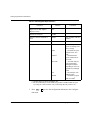
Table 2-7: Predictive Instrument Auto Report Options
Auto Interpretation
Selection
NOTE
2-18
Report Produced
Adult
09 report - TPI and ACI TIPI disabled
Pediatric
P4 report - TPI and ACI TIPI disabled
ACI-TIPI
T0 report - ACI TIPI only, TPI
disabled
TPI
H0 report - TPI only, no AMI
screening, ACI TIPI disabled
Default
09 or P4 report - with configured
settings
To produce a T8 report, ACI-TIPI and 08 adult criteria, refer to Table A-2 in
“Setting Up Your Cardiograph”
Recording an ECG
Choosing a Report Format
For additional information on the Predictive Instruments and associated
reports, refer to “Understanding ECG Analysis and the Predictive Instruments
Applications” and the Predictive Instruments Physician’s Guide.
The Auto ECG Report
Figure 2-1: The Auto ECG Report
2
A
D
B
E
C
G
F
H
B
K
I
L
J
M
Q
PageWriter 200/300pi M1771A/1770A Cardiograph
P
O
N
2-19
Choosing a Report Format
Table 2-8: Auto Report Annotations
Description
2-20
A
Patient ID number
B
Leads Off Status
C
Age and Sex
D
Patient Name
E
Weight
Height
F
Systolic/Diastolic Blood Pressure (BP)
G
Department
Room No.
Operator
H
Custom Field One
Custom Field Two
Note: These fields are for user-defined labels, such as insurance
number or medications.
I
Requested by: the name of the requesting physician
J
Basic measurements
K
Interpretation (300pi)
L
Reasons (300pi)
M
Calibration signal. See Table 2-10.
N
Sequence number—the total number of ECGs recorded over the life
of the cardiograph.
O
Filter settings:
* Artifact filter (F)
* AC filter(
)
* Frequency response
* Baseline Wander filter (W)
Recording an ECG
Choosing a Report Format
Table 2-8: Auto Report Annotations
Description
P
Cardiograph settings for speed, and for limb and chest lead
sensitivity.
Q
Location code and cardiograph ID number (Options #A05 or
StressWriter only)
Basic Measurements
The basic measurements table gives standard interval and duration
measurements in milliseconds, and limb lead axis measurements in degrees.
These are representative values for the dominant beat pattern in the ECG. For
more information on how representative beat measurements are derived, refer
to “How the PageWriter 200/300pi Measures ECGs” in “Understanding ECG
Analysis and the Predictive Instruments Applications”.
Table 2-9: Basic Measurements
Item
Description
Units
RATE
Heart rate
beats per minute
PR
PR interval
milliseconds
QRSD
QRS duration
milliseconds
QT
QT interval
milliseconds
QTC
QT interval corrected for rate
milliseconds
P
Frontal P axis
degrees
QRS
Frontal mean QRS axis
degrees
T
Frontal T axis
degrees
Calibration Signals
The following table shows how the height of the calibration pulse indicates
ECG sensitivity. Note that the display indicates sensitivity as:
PageWriter 200/300pi M1771A/1770A Cardiograph
2-21
2
Choosing a Report Format
l
l
l
l
l
l
1.0 (normal or 10 mm/mV),
1.0 ½V (normal for leads other than V-leads, half-normal or 5 mm/
mV for V-leads),
0.5 (half-normal or 5 mm/mV),
0.5 ½V (half-normal for leads other than V-leads, quarter-normal for
V-leads),
2.0 (twice-normal or 20 mm/mV), or
2.0 ½V (twice-normal for leads other than V-leads, normal for Vleads).
Table 2-10: Calibration Signals
ECG Size (mm/mV)
Display
Label
Limb Leads
V-leads
V1 - V6
Calibration Pulse
Auto
Manual
Limb
Leads
2-22
0.5
5
5
0.5 ½V
5
2.5
1.0
10
10
1.0 ½V
10
5
2.0
20
20
2.0 ½V
20
10
V-leads
Recording an ECG
Choosing a Report Format
Auto Report Examples
The following figures show examples of Auto ECG report formats.
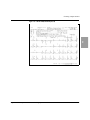
Figure 2-2: A Standard Auto 3x4 ECG (3x4)
2
PageWriter 200/300pi M1771A/1770A Cardiograph
2-23
Choosing a Report Format
Figure 2-3: An Auto 3x4 ECG with One Rhythm Strip (3x4, 1R)
Figure 2-4: An Auto 3x4 ECG with Three Rhythm Strips (3x4, 3R)
2-24
Recording an ECG
Choosing a Report Format
Figure 2-5: An Auto 6x2 ECG (6x2)
2
PageWriter 200/300pi M1771A/1770A Cardiograph
2-25
Choosing a Report Format
Figure 2-6: A Cabrera Auto 6x2 ECG (6x2)
2-26
Recording an ECG
Choosing a Report Format
Manual Report Examples
The following figures show examples of Manual ECG report formats.
Figure 2-7: A Manual 3-Lead ECG
2
PageWriter 200/300pi M1771A/1770A Cardiograph
2-27
Choosing a Report Format
Figure 2-8: A Manual 6-Lead ECG
2-28
Recording an ECG
Choosing a Report Format
Figure 2-9: A Manual 12-Lead ECG
2
PageWriter 200/300pi M1771A/1770A Cardiograph
2-29
Choosing a Report Format
Figure 2-10: The TPI Report (H0 page 1)
2-30
Recording an ECG
Choosing a Report Format
Figure 2-11: The TPI Report (H0 page 2)
2
PageWriter 200/300pi M1771A/1770A Cardiograph
2-31
Choosing a Report Format
Figure 2-12: The ACI-TIPI Report (T0)
2-32
Recording an ECG
Choosing a Report Format
Figure 2-13: The ACI-TIPI/Std Adult Report (T8)
2
PageWriter 200/300pi M1771A/1770A Cardiograph
2-33
Choosing a Report Format
Figure 2-14: The Risk Management Report (RM)
2-34
Recording an ECG
3 Understanding ECG Analysis and the Predictive
Instruments Applications
This chapter explains how the cardiograph measures, analyzes and interprets
(PageWriter 300pi only) ECG data, and what information is included on the
Extended Measurements report. In addition, the Predictive Instruments applications of the PageWriter 300pi are described.
Understanding the ECG Analysis Program
The ECG Analysis Program produces precise, accurate and consistent ECG
measurements. If desired, it further provides interpretive statements which
highlight key areas of concern for your review. These tools are most helpful if
you understand how and why they work and how you can best use their capabilities. Figure 3-1 shows this process.
PageWriter 200/300pi M1771A/1770A Cardiograph
3-1
3
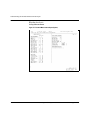
Understanding the ECG Analysis Program
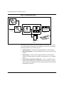
Figure 3-1: The ECG Analysis Program
ECG &
Patient Data
ECG Analysis Program
Feedback
to Operator
Quality Monitor
Measurements
Criteria
Extended
Measurement
Matrix
Interpretive
Report
Overreader
The analysis process begins with the simultaneous acquisition of the ECG’s
12 conventional leads. It then proceeds through four steps before producing
the interpreted ECG report. These steps are:
1. Quality Monitor—examines the technical quality of each ECG lead.
2. Pattern Recognition—locates and identifies the various waveform components.
3. Measurement—measures each component of the waveform and performs basic rhythm analysis, producing a comprehensive set of measurements.
4. Interpretation (PageWriter 300pi only)—uses the extended measurements, with information about the patient such as age and sex, to select
those interpretive statements from the criteria program which summarize
the findings for the ECG.
3-2
Understanding ECG Analysis and the Predictive Instruments Applications
How the PageWriter 200/300pi Measures ECGs
Agilent Technologies provides two standard criteria programs, adult and pediatric, for the PageWriter 300pi cardiograph. Patient information, including
age, sex, height, and weight can be used by the criteria programs in selecting
the interpretive statements.
NOTE
For more information about interpretation, see the Interpretive Cardiograph
Physician’s Guide.
How the PageWriter 200/300pi Measures ECGs
The PageWriter 200/300pi calculates measurements for all the waveforms
that you see on the Auto 3 x 4 report. Every beat in every lead is measured
individually, allowing the natural variations among beats to contribute to the
representative measurements. This is in contrast to other measurement methods in which a representative beat is constructed and then measurements are
made only for the constructed beat. In the PageWriter 200/300pi cardiograph,
representative group, lead and global measurements are calculated from combinations of the comprehensive set of measurements for each beat.
PageWriter 200/300pi M1771A/1770A Cardiograph
3-3
3
How the PageWriter 200/300pi Measures ECGs
Figure 3-2: ECG Morphology Measurements
Waveform Recognition
The first step of the measurement program involves waveform recognition
and beat detection. A boundary indicator waveform in which QRS complexes
and pacemaker spikes are enhanced is derived from all leads over the ten-second analysis period. After the approximate QRS complex and pacemaker
spike locations are known, another boundary indicator waveform that
enhances P and T wave detection is derived. Approximate P wave, QRS complex and T wave regions are then determined for each beat in the ECG.
Comprehensive Measurements
After the approximate waveform locations are known, they are further refined
to determine precise onsets and offsets for each waveform. Once onsets and
offsets are known, amplitude, duration, area and shape are calculated for
every P wave, QRS complex, T wave and ST segment in every lead that you
see on the Auto 3 x 4 report. Waveform irregularities such as notches, slurs,
delta waves and pacemaker spikes are also noted for every beat. A table of all
3-4
Understanding ECG Analysis and the Predictive Instruments Applications
How the PageWriter 200/300pi Measures ECGs
these measurements is created, from which the representative measurements
are calculated.
Group Measurements
After all the beats have been measured, each beat in the ECG is classified into
one of five rhythm groups based on rate and morphology parameters. Each
group consists of beats with similar R-R intervals, durations, and shapes,
except that all paced beats are grouped together, regardless of other parameters. Group 1 represents the type of beat that is most normal or predominant
and groups 2 through 5 represent other beat types. The group into which each
beat is classified is noted under the heading “Rhythm Grouping of Beats” on
the Extended Measurements report. Group measurements are calculated by
averaging the measurements for all the beats in each of the groups and are
reported in the Rhythm Analysis section of the Extended Measurements
report.
Lead Measurements
Representative measurements for each of the 12 leads are calculated from the
comprehensive set of measurements for all the beats in the ECG. Only the
beats of the predominant group (Group 1) are used. If a particular lead (as
shown on the Auto 3 x 4 report) does not have any Group 1 beats, a beat group
with similar parameters is used, if possible. The measurement program tries to
select a beat group for which the beats are not paced. Only if all beats in the
ECG are paced will the measurements be for paced beats. If there are paced
and non-paced beats in an ECG, only the non-paced beats will be measured,
which may result in leads for which no measurements are reported.
In each lead, the measurements for all the beats belonging to the selected beat
group are averaged. The lead measurements are representative of the dominant waveform present in each lead and are reported in the Morphology Analysis section of the Extended Measurements report.
Atrial Rhythm Analysis
Atrial rhythm is determined by examining leads V1, aVF, II and III in succession until the program can report conclusively that there are multiple P waves,
that there are no P waves, or that there is one P wave per QRS complex. If a
conclusive result is achieved, then the last lead analyzed will be used to calcu-
PageWriter 200/300pi M1771A/1770A Cardiograph
3-5
3
How the PageWriter 200/300pi Measures ECGs
late group and global atrial rhythm parameters. If no conclusive result is
achieved, no atrial rhythm parameters are calculated.
Global Measurements
The global measurements for the ECG, including the frontal and horizontal
plane axis measurements, are reported to the right of the lead measurements in
the Morphology Analysis section of the Extended Measurements report.
These interval, duration, and segment measurements are weighted averages of
the lead measurements. The global rate reported is the mean ventricular rate
over the entire ECG unless the ECG criteria program determines that one of
the group mean ventricular rates is more representative of the underlying
rhythm.
Axis Measurements
Although when making axis measurements manually, it is most convenient to
use waveform amplitudes, using areas yields more accurate results. The PageWriter 200/300pi uses the waveform areas from the lead measurements in calculating the P, QRS and T axes, while the sum of the ST onset, middle and end
amplitudes is used in calculating the ST axis. For the frontal plane axis measurements, which use the limb leads, nine lead pairs, all at least 60 degrees
apart, are used to estimate the axes. The resulting estimates are examined to
ensure that they converge to a single result. If so, they are averaged to form
the representative axis measurement. The horizontal plane axis measurements, which use leads V1-V6, are calculated similarly from seven lead pairs.
The representative measurements are reported on the Extended Measurements
report.
3-6
Understanding ECG Analysis and the Predictive Instruments Applications
Automatically Measuring and Interpreting ECGs
Automatically Measuring and Interpreting ECGs
The PageWriter 200/300pi uses the ECG Analysis Program to produce precise, accurate and consistent ECG measurements. In the PageWriter 300pi, the
program further provides interpretive statements that highlight key areas of
concern for your review. The primary objective of interpretation is to help the
physician in making a clinical diagnosis. The interpreted results are best used
in conjunction with the physician’s knowledge of the patient, the results of the
physical examination, the ECG tracing, and other findings. This tool is most
helpful, however, if you understand how and why it works, and how you can
best use its capabilities.
The ECG Analysis Program uses the following patient ID entries for interpretation: age, sex, height, and weight.
See the Physician’s Reference Guide (part number M1700-92908) for detailed
information about the ECG Analysis Program.
3
PageWriter 200/300pi M1771A/1770A Cardiograph
3-7
Understanding the Extended Measurements Report
Understanding the Extended Measurements
Report
The Extended Measurements Report
The two-part Extended Measurements report summarizes the morphology and
rhythm characteristics for the individual leads and rhythm groups in the ECG.
The ECG Analysis Program uses the Extended Measurements report information to generate interpretive statements. An Extended Measurements report is
available for each ECG when it is recorded or later if the ECG is stored.
To print a copy of the extended measurements report for the most recent ECG,
press the 6KLIW and &RS\ keys at the same time.)
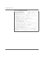
Figure 3-3: An Extended Measurements Report (Morphology)(
3-8
Understanding ECG Analysis and the Predictive Instruments Applications
Understanding the Extended Measurements Report
Morphology Analysis
The following tables define the parameters in the order that they appear on the
morphology analysis page of the extended measurements report.
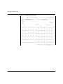
Individual Lead Measurements
Table 3-1 lists every representative measurement in each lead. The parameters
in the following tables are shown in Figure 3-4.
Figure 3-4: ECG Morphology Measurements
3
Table 3-1: Individual Lead Measurements
Parameter
Units or
Value
Description
P AMP
millivolts
P wave amplitude
P DUR
milliseconds
P wave duration
PageWriter 200/300pi M1771A/1770A Cardiograph
3-9
Understanding the Extended Measurements Report
Table 3-1: Individual Lead Measurements (Continued)
Parameter
3-10
Units or
Value
Description
P AREA
Ashman
units
(40 ms x 0.1
mV)
P wave area for monophasic P waves or the area
of the initial portion of a biphasic P wave.
P NOTCH
Yes or No
Indicates the presence or absence of a notch in the
P wave.
P’ AMP
millivolts
P’ wave amplitude
P’ DUR
milliseconds
P’ wave duration
P’ AREA
Ashman
units
(40 ms x 0.1
mV)
Area of the terminal portion of a biphasic P wave.
Q AMP
millivolts
Q wave amplitude
Q DUR
milliseconds
Q wave duration
R AMP
millivolts
R wave amplitude
R DUR
milliseconds
R wave duration
S AMP
millivolts
S wave amplitude
S DUR
milliseconds
S wave duration
R’ AMP
millivolts
R’ wave amplitude
R’ DUR
milliseconds
R’ wave duration
S’ AMP
millivolts
S’ wave amplitude
S’ DUR
milliseconds
S’ wave duration
QRSAREA
Ashman
units
(40 ms x 0.1
mV)
The area of the QRS complex.
Understanding ECG Analysis and the Predictive Instruments Applications
Understanding the Extended Measurements Report
Table 3-1: Individual Lead Measurements (Continued)
Parameter
Units or
Value
Description
QRSNTCH
+ or -
Indicates a notch in the QRS complex.
A + indicates a notch or slur in the R or R’ wave.
A - indicates a notch or slur in the Q, S, or S’
wave.
DELTA
Yes or No
Indicates the presence or absence of pronounced
delta waves preceding QRS complexes.
ST ON
millivolts
Elevation or depression at the onset (J point) of
the ST segment.
ST MID
millivolts
Elevation or depression at the midpoint of the ST
segment.
ST 80ms
millivolts
Elevation or depression of the ST segment 80 ms
after the end of the QRS complex (J point).
ST END
millivolts
Elevation or depression at the end of the ST segment.
ST DUR
milliseconds
ST segment duration.
STSLOPE
degrees
ST segment slope. Slope is measured in degrees
and can range from 0 to ± 90 degrees
STSHAPE
-, V, or ^
The ST segment shape:
- = Straight
V = Concave upward
^ = concave downward
T AMP
millivolts
T wave amplitude
T DUR
milliseconds
T wave duration
T AREA
Ashman
units
(40 ms x 0.1
mV)
T wave area for monophasic T waves or the area
of the initial portion of a biphasic T wave.
T NOTCH
Yes or No
Indicates the presence or absence of a notch in the
T wave.
PageWriter 200/300pi M1771A/1770A Cardiograph
3-11
3
Understanding the Extended Measurements Report
Table 3-1: Individual Lead Measurements (Continued)
Parameter
3-12
Units or
Value
Description
T’ AMP
millivolts
T’ wave amplitude
T’ DUR
milliseconds
T’ wave duration
T’ AREA
Ashman
units
(40 ms x 0.1
mV)
Area of the terminal portion of a biphasic T wave.
PR INT
milliseconds
Interval from the onset of the P wave to the onset
of the QRS complex.
PR SEG
milliseconds
Interval from the end of the P wave to the onset of
the QRS complex.
V.A.T.
milliseconds
Ventricular Activation Time: the interval from the
onset of the QRS complex to the latest positive
peak in the complex, or the latest substantial
notch on the latest peak, whichever is later.
QRS PPK
millivolts
Peak-to-peak QRS complex amplitude.
QRS DUR
milliseconds
QRS complex duration, measured from its onset
to the ST segment onset (J point).
QT INT
milliseconds
Interval from the onset of the QRS complex to the
end of the T wave.
GROUP
1 (or 2 - 5)
Indicates the rhythm group used to derive the representative measurements for each lead. Will be
Group 1 unless no Group 1 beats were detected
during the analysis interval for this lead.
Understanding ECG Analysis and the Predictive Instruments Applications
Understanding the Extended Measurements Report
Table 3-1: Individual Lead Measurements (Continued)
Parameter
Units or
Value
Description
QUALITY
N/A
Each character indicates a type of noise present in
the lead:
D - Baseline wander indicator. The onsets of two
successive QRS complexes differ by more than 1/
3 the calibration value.
T - Artifact, most likely muscle tremor. Occurs
when more than 16 up-and-down strokes exceeding 1 mm in amplitude are detected within 1 second.
W -Steady baseline drift exceeding 10 mm/sec.
A -Power line (AC) noise.
M -Missing lead.
NOISE
N/A
Indicates the severity of artifact reflected in the
signal data:
blank = Light noise
1 = Moderate noise
2 = Marked noise
3 = Severe noise
3
An Ashman unit is the area of 1 square millimeter at normal speed (25 mm/
sec) and normal sensitivity (10 mm/mV). An Ashman unit equals 40 ms x 0.1
mV.
PageWriter 200/300pi M1771A/1770A Cardiograph
3-13
Understanding the Extended Measurements Report
Cal Factors
The factor by which the ECG trace differs from standard scaling (10 mm/
mV). Standard scaling is indicated by a CAL factor of 1.00.
Table 3-2: Cal Factors
Parameter
Units or Value
Description
**Cal
Assumed**
Appears only
when true
The cal pulses were measured to be of
non-standard amplitude or shape. This
may indicate a cardiograph
malfunction.
**Paced Beats
Measured**
Appears only
when true
All beats are paced and measurements
are for paced beats.
**QRS-like Artifact Detected**
Appears only
when true
Spike-like artifact was detected that may
have caused measurement error.
**Cart 1/2V**
Appears only
when true
Cart was set to print chest leads at half
the scale of the limb leads.
**Computer 1/
2V**
Appears only
when true
The ECG Management System automatically scaled the chest leads at half the
scale of the limb leads. This message
can only appear on ECGs printed by the
ECG Management System.
Frontal/Horizontal
The following table lists frontal plane and horizontal plane axis parameters
and the global measurements representative of the entire ECG.
Table 3-3: Frontal/Horizontal
Parameter
3-14
Units or Value
Description
P
degrees
P wave axis.
I:40
degrees
Initial 40 ms QRS complex axis.
QRS
degrees
Mean QRS complex axis.
T:40
degrees
Terminal 40 ms QRS complex axis.
Understanding ECG Analysis and the Predictive Instruments Applications
Understanding the Extended Measurements Report
Table 3-3: Frontal/Horizontal
Parameter
Units or Value
Description
ST
degrees
ST segment axis.
T
degrees
T wave axis.
Mean Ventr.
Rate
beats per
minute
Representative ventricular rate for the
entire ECG.
Mean PR Int.
milliseconds
Representative PR interval for the entire
ECG.
Mean PR Seg.
milliseconds
Representative PR segment for the entire
ECG.
Mean QRS
Dur.
milliseconds
Representative QRS duration for the entire
ECG.
Mean QT Int.
milliseconds
Representative QT interval for the entire
ECG.
Mean QTc
milliseconds
Representative QT interval adjusted to a
heart rate of 60 beats/minute.
3
Analysis Statement Codes (PageWriter 300pi only)
These codes are the criteria codes for the interpretive statements printed on
the Interpretive report.
PageWriter 200/300pi M1771A/1770A Cardiograph
3-15
Understanding the Extended Measurements Report
Rhythm Analysis
Group Measurements
Figure 3-5: Extended Measurements Report (Rythm)
3-16
Understanding ECG Analysis and the Predictive Instruments Applications
Understanding the Extended Measurements Report
The following are parameters given for each rhythm group detected by the
PageWriter 200/300pi during the analysis interval.
Table 3-4: Group Measurements
Units or
Value
Parameter
Description
Member Count
N/A
Number of beats in the rhythm group.
Member%
percentage
Percentage of the total number of beats represented by the rhythm group.
Longest Run
N/A
Longest contiguous run of beats in the
rhythm group.
Mean QRS
Duration
milliseconds
Average QRS duration in the rhythm group.
Low Ventr Rate
beats per
minute
Lowest ventricular rate in the rhythm group.
Mean Ventr
Rate
beats per
minute
Average ventricular rate in the rhythm group.
High Ventr Rate
beats per
minute
Highest ventricular rate in the rhythm group.
V-Rate Std.
Dev.
N/A
Standard deviation of the ventricular rate in
the rhythm group.
Mean RR Interval
milliseconds
Average interval between R waves in the
rhythm group.
Mean Atrial
Rate
N/A
Average atrial rate in the rhythm group.
A-Rate Std.
Dev.
N/A
Standard deviation of the atrial rate in the
rhythm group.
Avg. P Count
N/A
Average number of P waves per QRS complex in the rhythm group.
# Not Avg P
Beats
N/A
Number of QRS complexes in the rhythm
group which do not have the average number
of P waves per QRS complex.
PageWriter 200/300pi M1771A/1770A Cardiograph
3
3-17
Understanding the Extended Measurements Report
Table 3-4: Group Measurements
Parameter
3-18
Units or
Value
Description
Low PR Interval
milliseconds
Shortest PR interval in the rhythm group.
Mean PR Interval
milliseconds
Average PR interval in the rhythm group.
High PR Interval
milliseconds
Longest PR interval in the rhythm group.
PR Int. Std.
Dev.
N/A
Standard deviation of the PR interval in the
rhythm group.
Mean PR Segment
milliseconds
Average PR segment in the rhythm group.
Mean QT Interval
milliseconds
Average QT interval in the rhythm group.
Comp. Pause
Count
N/A
Number of beats followed by a compensatory pause in the rhythm group.
Understanding ECG Analysis and the Predictive Instruments Applications
Understanding the Extended Measurements Report
Group Flags
The parameters in this part of the rhythm analysis indicate the presence or
absence of various rhythm-related conditions in the rhythm groups identified.
Table 3-5: Group Flags
Parameter
Units or
Value
Artificial Pace
Yes or No
Indicates that beats in the rhythm group are
paced. All paced beats are grouped together.
Interpolated
Beat
Yes or No
Indicates that the rhythm group contains
only interpolated beats.
Sinus Arrest
Yes or No
Indicates a prolonged R-toR interval. Set for
the sinus arrest resumption group.
PR Progress
Longer
Yes or No
Indicates the PR interval is getting progressively longer in the rhythm group.
Wenckebach
Yes or No
Indicates presence of the Wenckebach phenomenon in the rhythm group.
Bigeminy
Yes or No
Indicates presence of a bigeminy rhythm. Set
for the group consisting of ectopic beats.
Trigeminy
Yes or No
Indicates presence of a trigeminy rhythm.
Set for the group consisting of ectopic beats.
Aberrant Shape
Yes or No
Indicates that beats in the rhythm group are
in the minority and are wider than other
beats from the same lead(s).
Mult. P Test
Done
Yes or No
Indicates that beats in the rhythm group were
tested for multiple P waves.
QRS Measured
Yes or No
Indicates that QRS-related parameters were
measured in the rhythm group.
PageWriter 200/300pi M1771A/1770A Cardiograph
Description
3
3-19
Understanding the Extended Measurements Report
Global Rhythm Parameters
The following parameters provide global information for beats in the ECG.
Table 3-6: Global Rhythm Parameters
Parameter
3-20
Units or Value
Description
Atrial Rate
Beats per minute
The representative atrial rate for the analysis
interval. This is not a simple arithmetic average.
Low Ventr Rate
Beats per minute
The lowest ventricular rate during the analysis
interval.
Mean Ventr Rate
Beats per minute
The average ventricular rate during the analysis
interval.
High Ventr Rate
Beats per minute
The highest ventricular rate during the analysis
interval.
Flut-Fib Indicator
N/A
Indicates approximate number of flutter-like or
coarse fibrillatory waves per lead.
Fixed Mult P Morph
Yes or No
Indicates that all P waves are of consistent morphology.
Mult P Test Valid
Yes or No
Indicates that the tests performed to detect multiple P waves produced consistent results.
Delta Wave Count
N/A
Number of QRS complexes with pronounced
delta waves.
Delta Wave%
Percentage
Percent of total beats with pronounced delta
waves.
Bigeminy Count
N/A
Total number of beats in a bigeminy pattern,
whether or not they are contiguous.
Bigeminy String
N/A
Total number of beats in the longest continuous
bigeminy pattern.
Trigeminy Count
N/A
Total number of beats in a trigeminy pattern,
whether or not they are contiguous.
Understanding ECG Analysis and the Predictive Instruments Applications
Understanding the PageWriter 300pi Predictive Instrument Applications
Parameter
Units or Value
Description
Trigeminy String
N/A
Total number of beats in the longest continuous
trigeminy pattern.
Wenckebach Count
N/A
Total number of Wenckebach cycles.
A Wenckebach cycle is a series of beats whose
PR intervals grow progressively longer, culminating in an unusually long RR interval, (a
dropped beat).
Wenckebach String
N/A
The number of beats preceding the dropped
beat.
Rhythm Grouping of Beats
The Rhythm Grouping of Beats is a number string which relates spatially to
the beats in the ECG and shows the rhythm group number for each beat as
determined by the Rhythm Analysis portion of the Analysis Program.
Possible values are:
1,2,3,4, or 5
Rhythm group number
0
Beat unclassifiable by program
——
Lead switching interval
NO MEAS
Program unable to measure any beats in the
lead set.
Understanding the PageWriter 300pi Predictive
Instrument Applications
The ACI TIPI (Acute Cardiac Ischemia- Time Insensitive Predictive Instrument) and the TPI (Thrombolytic Predictive Instrument) are software products that enhance the computer-assisted ECG analysis capabilities of the
PageWriter 300pi Cardiograph. These "Predictive Instruments" generate 0100% Predicted Probability scores of ACI (Acute Cardiac Ischemia) and
patient outcome with and without thrombolytic therapy for acute myocardial
infarction (AMI). These predicted probabilities are based on ECG features,
PageWriter 200/300pi M1771A/1770A Cardiograph
3-21
3
Understanding the PageWriter 300pi Predictive Instrument Applications
patient age, gender, blood pressure, chest pain status and time since ischemic
symptom onset. The cardiograph can be configured to automatically print
these probabilities on the Auto ECG report.
Figure 3-6 illustrates the Predictive Instrument Application process. If TPI is
enabled, the Predictive Instrument Application produces the H0 report. If
ACI-TIPI is enabled, the Predictive Instrument Application produces the RM,
T0, and 09 reports.
Figure 3-6: The Predictive Instrument Application
Report Types
09 - Standard Adult Criteria
T0 - ACI -TIPI
RM - Risk Management
H0 - TPI
ECG & Patient Data
Acute Cardiac
Ischemia
Time Insensitive
Predictive
Instrument
Thrombolytic
Predictive
Instrument
09 Report
RM Report
H0 Report
T0 Report
Indications for Use
The ACI-TIPI is intended for use as an aid to clinicians in the diagnosis and
triaging decision process of patients with ACI, which includes unstable
angina pectoris and acute myocardial infarction (AMI).
3-22
Understanding ECG Analysis and the Predictive Instruments Applications
Understanding the PageWriter 300pi Predictive Instrument Applications
The TPI is intended for use as an aid to clinicians identifying which patients
with AMI are appropriate candidates for thrombolytic therapy. TPI is intended
for adult patients, aged 35-75, diagnosed with symptoms of acute myocardial
infarction.
These programs can be used in real-time and retrospective settings since they
rely on information that is readily available in the emergency department
(ED), or by retrospective review of the patient’s medical record. The emergency physician’s real-time decision making process is aided by having the
predictive instruments incorporated into the electrocardiograph. The predictive scores, once acquired, can then be used along with actual patient outcome
to help improve patient management practices retrospectively.
The predictive instruments provide the physician with tools to:
l
l
l
NOTE
Aid diagnosis and triage of some patients with symptoms suggestive
of ACI
Identify those patients most likely to benefit from thrombolytic therapy
Facilitate the earliest possible administration of thrombolytic therapy
For intended use and contraindication information, consult the Predictive
Instrument Physician’s Guide for important information.
Understanding TPI Variables
There are nine predictors of thrombolytic-related benefits and risks which
include six clinical factors and detailed information on three ECG features.
The six clinical factors are:
l
l
l
l
l
l
Time since ischemic onset
Patient age
Patient gender
Patient Blood Pressure (systolic and diastolic)
Patient’s history of diabetes
Patient’s history of hypertension
PageWriter 200/300pi M1771A/1770A Cardiograph
3-23
3
Understanding the PageWriter 300pi Predictive Instrument Applications
The three ECG features are:
l
l
l
the presence or absence of pathological or significant Q waves
the presence and degree of ST segment elevation or depression
the presence and degree of T wave elevation or inversion
Understanding ACI TIPI Variables
Seven variables are used to predict Acute Cardiac Ischemia. These variables
include four clinical factors and detailed information on three ECG features.
The four clinical factors are:
l
l
l
l
the presence or absence of chest pain or pressure, or left arm pain
whether chest pain or pressure, or left are pain is the patient’s most
important presenting symptom
patient age
patient gender
The three ECG features are:
l
l
l
the presence or absence of pathological or significant Q waves
the presence and degree of ST segment elevation or depression
the presence and degree of T wave elevation or inversion
The four clinical factors must be entered by the clinician before a ACI TIPI
analysis can be performed.
The exclusionary cases for both the TPI and ACI TIPI applications are listed
in the Predictive Instrument Physician’s Guide. Please refer to this document
for this information.
3-24
Understanding ECG Analysis and the Predictive Instruments Applications
Understanding the PageWriter 300pi Predictive Instrument Applications
Using the TPI and ACI TIPI Applications
To use the TPI and ACI TIPI applications, you must configure the cardiograph and enable the applications. There are several types of reports that are
produced by the cardiograph. These reports are summarized in Table 3-7.
Table 3-7: PageWriter 300pi Reports
Report Type
Contents of Report
Standard 09 (Std 09)
ECG waveforms, measurements, ECL 09 Adult
Interpretation
Standard P4 (Std P4)
ECG waveforms, measurements, ECL P4 Pediatric Interpretation
ACI-TIPI (T0)
ECG waveforms, TIPI
Analysis,
No Risk Management
Report
Risk Management
Risk Management Report
—1 page summarizing
clinical information and
can be used by the Clinician to document clinical
decisions
TPI (H0)
ECG waveforms, TPI
Analysis
08/ACI-TIPI (T8)
ECG waveforms, measurements, ECL 08 Adult
Interpretation and ACITIPI Analysis
PageWriter 200/300pi M1771A/1770A Cardiograph
Notes
3
Only available when
T0 is enabled
3-25
Understanding the PageWriter 300pi Predictive Instrument Applications
NOTE
To configure your cardiograph to interpret with ECL 08 criteria without the
ACI-TIPI analysis, perform the following steps:
1. From the Configuration Menu, select Setup Predictive Instruments.
2. From the Setup Predictive Instruments Menu, set ’Interp Criteria?’ to
Adult 08/TIPI."
3. Exit the Setup Predictive Instruments Menu and return to the configuration
menu by pressing ’Exit’.
4. Use the arrow keys and select Setup ID Entry
5. Disable the ’Chest/LA Pain’ entry by selecting ’No’.
6. Save this configuration by pressing ’Exit’.
Analyzing an ECG with the Predictive Instruments
The flexibility of the PageWriter 300pi allows you to configure the Predictive
Instruments based on the type of patients presenting in your clinical setting.
Figure 3-6 illustrates the method by which the PageWriter 300pi processes an
ECG and prints reports. Using the Configuration Menu, you can setup your
cardiograph to provide the desired analysis.
Obtaining Alternate Reports
To obtain other Auto reports without changing the global configuration, the
PageWriter 300pi features softkeys which can be selected quickly.
1. From the main display, press the ) key until 'Auto Analysis' appears.
2. Press the ) key to select the desired report format.
This will not change the global cardiograph configuration. The cardiograph
will revert to the last saved storage/transmission configuration options if the
cardiograph is powered off. The only desired report is printed and the appropriate Predictive Instruments are enabled depending on the choice.
3-26
Understanding ECG Analysis and the Predictive Instruments Applications
4 ECG Storage (Options #A05 or StressWriter)
This chapter contains information about storing ECGs using the internal
memory of the PageWriter 200/300pi, Options #A05 or StressWriter. Information about using and printing the Log of ECGs Taken and the Log of ECGs
Stored is also included.
Advantages of Storage
Storing ECGs allows you to recall the ECGs later as needed. Individual ECGs
or groups of ECGs can be recalled for re-analyzing, editing, printing, or transmitting.
ECGs are stored at a resolution of 500 samples per second, and include a full
ten seconds of data for all leads. Up to thirty Auto ECGs may be stored in the
internal memory. Only Auto ECGs can be stored. Manual ECGs cannot be
stored. An ECG must be stored before it can be transmitted.
When you finish acquiring and printing an ECG, you can choose whether or
not to store it. You can store an ECG without entering patient ID information.
The cardiograph records the ECG with a patient ID of “Unknown”. If you
store the ECG with no patient ID information or with partial ID information,
you can edit the patient ID information later, and then reprint the edited
reports. The PageWriter 200/300pi stores the ECG measurements and the
ECG copy interpretation.
PageWriter 200/300pi M1771A/1770A Cardiograph
4-1
4
Storing ECGs
Storing ECGs
To store the ECG, perform the following steps:
1. After the ECG report prints, the following message will appear on the
screen:
Store ECG?
Patient ID: 23456
Name: Ian Harrison
Yes
F1
No
F2
F4
F3
F5
2. Press Yes ( ) ) to store the ECG,
OR
press No ( ) ) to continue without storing the ECG.
NOTE
If you select No , you cannot store the ECG later, or transmit the ECG.
3. If you select Yes , the message “Storing ECG...” appears on the
screen until storage is complete.
4-2
ECG Storage (Options #A05 or StressWriter)
Storing ECGs
4. If the storage memory is full when you attempt to store an ECG, the following screen appears:
Storage system is full.
Do you want to delete
an old ECG?
Yes
F1
No
F2
F4
F3
F5
4
5. Press Yes ( ) ) to delete one or more old ECGs. The Manage Stored
ECGs screen will appear. The ECGs will be listed oldest first and most
recent last. See the next section, “Managing Stored ECGs” , for information on deleting ECGs.
OR
Press No ( ) ) to return to the “Store ECG?” screen. Press No ( ) )
to continue without storing the ECG.
PageWriter 200/300pi M1771A/1770A Cardiograph
4-3
Managing Stored ECGs
Managing Stored ECGs
Your PageWriter 200/300pi cardiograph with Options #A05 or StressWriter
allows you to print, delete, and edit the patient ID information for stored
ECGs. You cannot edit the date or time the ECG was acquired, the ECG measurements, or the ECG interpretive statements.
Selecting Stored ECGs
To select an ECG for printing, deletion, or editing the patient ID information,
perform the following steps:
1. Press the
key. The main menu appears.
Your Institution Label
12:12:04 Fri 26 June 1998
Main Menu
Transmit and Fax ECGs
Request a remote ECG
Manage stored ECGs
Print the Log of ECGs Stored
Print the Log of ECGs Taken
Print the Configuration
Configure the Cardiograph
Exit
Select
F1
4-4
F2
F3
F4
F5
ECG Storage (Options #A05 or StressWriter)
Managing Stored ECGs
2. Select Manage Stored ECGs from the menu by pressing
to move the cursor down, or by pressing
or
or
to move the cursor up
until the selection is highlighted.
3. Press Select ( ) ) or
to display the Manage Stored ECGs menu.
Manage Stored ECGs
(30 ECGs stored)
Screen 2 of 5
Patient Name/ID
Time and Date
Ian Harrison
ID: 23456
00:37:58
6-Apr-98
Katharina Schmidt
ID: 56321
09:17:35
9-Apr-98
John Picard
14:53:07
9-Apr-98
10:34:45
11-Apr-98
Renate Desimone
ID: 78654
Print
Delete
Select
Edit
ID
Exit
F1
F2
F3
F4
F5
4. Select the desired ECG from the list by pressing
down, or by pressing
4
to move the cursor
to move the cursor up until the ECG if high-
lighted.
NOTE
You can move to the previous page by pressing
until ECGs from the pre-
vious page appear at the top of the screen. You can move to the next page by
pressing
until ECGs from the next page appear at the bottom of the
screen.
PageWriter 200/300pi M1771A/1770A Cardiograph
4-5
Managing Stored ECGs
5. Press Select ( ) ) to select the ECG. An asterisk appears to the left of
selected ECGs. The Select softkey changes to Unselect when a selected
ECG is highlighted.
NOTE
You can select multiple ECGs to print or delete. For editing the patient ID
information, you can select only one ECG at a time.
Printing Stored ECGs
Print previously selected ECGs by pressing Print ( ) ). The ECGs will print
with the speed and format most recently selected for printed reports. These
settings are shown on the idle screen. If you want to print an ECG using a different format or speed than used on the original printed report, you can use the
configuration menu or the front panel keys to change the report settings
before printing. See Configuring Your Cardiograph, for information about
changing report format and speed.
NOTE
The cardiograph cannot record an ECG or perform other functions while
printing a stored ECG.
Deleting Stored ECGs
Delete previously selected ECGs by pressing Delete ( ) ).
CAUTION
4-6
You cannot retrieve a deleted ECG.
ECG Storage (Options #A05 or StressWriter)
Managing Stored ECGs
Editing Patient ID for Stored ECGs
Edit the patient ID information by performing the following steps:
1. Press EditID ( ) ). The ID Edit screen appears.
ID Edit
Patient ID: 23456
Name: Ian Harrison
Age: 54 Years
Height: 180 cm
Weight: 82 Kg
Blood Pressure: 130/80
Operator:
Department:
Room:
Requested by:
Custom Field One:
Custom Field two:
Set ECG Mgmt Priority to Stat?:
Exit
Erase
F1
F2
F3
F4
F5
4
2. Select the field you want to change by pressing
cursor down, or by pressing
or
or
to move the
to move the cursor up until the
field is highlighted.
3. Use the Erase key ( ) ) to remove old information.
4. Type the new information in the field.
5. When you finish making changes, press Exit ( ) ).
PageWriter 200/300pi M1771A/1770A Cardiograph
4-7
Printing the Log of ECGs Taken or the Log of ECGs Stored
If you are using a PageWriter 300pi, the ECG will be re-interpreted and
stored. The message Analyzing... appears on the screen during re-interpretation. The message Storing ECG... appears while the ECG is being
stored.
Printing the Log of ECGs Taken or the Log of
ECGs Stored
To print the Log of ECGs Taken or the Log of ECGs Stored, perform the following steps:
1. Press the
key. The main menu appears.
Your Institution Label
12:12:04 Fri 26 June 1998
Main Menu
Transmit and Fax ECGs
Request a remote ECG
Manage stored ECGs
Print the Log of ECGs Stored
Print the Log of ECGs Taken
Print the Configuration
Configure the Cardiograph
Exit
Select
F1
F2
F3
F4
F5
2. Select Print the Log of Stored ECGs or Print the Log
of ECGs Taken from the menu by pressing
or
to move the
4-8
ECG Storage (Options #A05 or StressWriter)
Printing the Log of ECGs Taken or the Log of ECGs Stored
cursor down, or by pressing
or
to move the cursor up until the
desired menu selection is highlighted.
3. Press 6HOHFW ( ) ) or
ECGs stored
to print the log of ECGs taken or the log of
The cardiograph automatically maintains two ECG logs: the Log of ECGs
Taken and the Log of ECGs Stored.
The Log of ECGs Taken is a list of the last sixty (60) Manual and Auto ECGs
recorded on the cardiograph. The ECGs are listed in chronological order, with
the most recent ECG first. When more than sixty (60) ECGs fill the list, the
oldest ECGs disappear from the list when a new one is added.
Figure 4-1: Log of ECGs Taken
A
C
D
E
F
B
G
H
I
M1770A PageWriter 300pi
J
K
L MN
12:12:04 Fri 26 June 1998
Log of ECGs Taken
Seq#
Date
Time
Patient ID Patient Name
Mode Oper
Dept
Location
T
E
A
4
PageWriter 200/300pi M1771A/1770A Cardiograph
4-9
Printing the Log of ECGs Taken or the Log of ECGs Stored
Table 4-1: The Log of ECGs Taken
Description
4-10
A
Log Title
B
Date and time of the report
C
Sequence number of the ECG
D
Date the ECG was taken
E
Time the ECG was taken
F
Patient identification number
G
Patient name
H
Mode used to record the ECG (Auto or Manual)
I
Person who recorded the ECG
J
Department identification number
K
Location code and cardiograph ID code
L
ECG transmitted indicator: (Y for transmitted, N for not transmitted)
M
Patient ID edit indicator (Y for edited, N for not edited)
N
Version of the criteria used to interpret the ECG
ECG Storage (Options #A05 or StressWriter)
Printing the Log of ECGs Taken or the Log of ECGs Stored
The Log of ECGs Stored lists all Auto ECGs stored in the cardiograph’s internal memory. The Log of ECGs Stored is updated automatically when you
store an ECG, and when you delete a stored ECG.
Figure 4-1Log of ECGs Stored
A
C
D
E
F
G
B
H
I
M1770A PageWriter 300pi
J
K
L MN
12:12:04 Fri 26 June 1998
Log of ECGs Stored
Seq#
Date
Time
Patient ID Patient Name
Mode Oper
Dept
Location
T
E
A
23 ECGs stored, 7 storage spaces available
O
P
4
PageWriter 200/300pi M1771A/1770A Cardiograph
4-11
Printing the Log of ECGs Taken or the Log of ECGs Stored
Table 4-2: The Log of Stored ECGs
Description
4-12
A
Log Title
B
Date and time of the report
C
Sequence number of the ECG
D
Date the ECG was taken
E
Time the ECG was taken
F
Patient identification number
G
Patient name
H
Mode used to record the ECG (Auto or Manual)
I
Person who recorded the ECG
J
Department identification number
K
Location code and cardiograph ID code
L
ECG transmitted indicator: (Y for transmitted, N for not transmitted)
M
Patient ID edit indicator (Y for edited, N for not edited)
N
Version of the criteria used to interpret the ECG
O
Number of ECGs stored
P
Number of ECG storage spaces available
ECG Storage (Options #A05 or StressWriter)
5 Transmitting, Faxing, and Receiving Auto ECGs
(Options #A05 or StressWriter only)
If your PageWriter 200/300pi cardiograph is equipped with Options #A05 or
StressWriter, it can transmit and receive ECGs. The cardiograph must be configured for these functions before using them. For more information about
configuring your cardiograph for transmitting and receiving ECGs, see Configuring Your Cardiograph, and Setting Up Your Cardiograph.
Transmitting ECGs
Your PageWriter 200/300pi cardiograph can transmit Auto ECGs to another
PageWriter 200, 200i or 300pi equipped with Options #A05 or StressWriter,
to a PageWriter XLi cardiograph, to a TraceMaster ECG Management System, or to a Group III facsimile machine.
NOTE
You cannot transmit Manual ECGs. You can transmit only ECGs that have
been stored.
If you are transmitting an ECG analyzed with ECL 09 criteria to a TraceMaster or ECG Manager system, you must first load the ECL 09 criteria on the
receiving TraceMaster or ECG Manager system. Please contact your local
Agilent Technologies representative for assistance or details on adding the
ECL 09 criteria.
5
Four typical ECG transmission situations are:
l
l
An ECG transmitted from the cardiograph at the bedside to a TraceMaster ECG Management System for printing, overreading, and storing.
ECGs recorded on rounds and then transmitted to another PageWriter
cardiograph or a TraceMaster Management System in another area of
the institution.
PageWriter 200/300pi M1771A/1770A Cardiograph
5-1
Transmitting ECGs
l
l
An ECG sent to another institution for overreading or further analysis.
An ECG sent to a PC with ECG Manager software.
NOTE
If you transmit an ECG from a PageWriter 300pi with ECL 09 interpretation
to either a PageWriter 200i with ECL 08 only or a TraceMaster without ECL
09 criteria, the resulting printed report will consist of ECG waveforms and
measurements only.
WARNING
Equipment connected to the cardiograph’s RS-232 connector can cause ground leakage current exceeding the maximum specified in IEC 601-1 safety standards. Do not
connect any equipment to the RS-232 connector during cardiograph operation when
the patient cable is connected to a patient.
To transmit an ECG, perform the following steps:
1. Press the
5-2
key. The main menu appears.
Transmitting, Faxing, and Receiving Auto ECGs (Options
Transmitting ECGs
Your Institution Label
12:12:04 Fri 26 June 1998
Main Menu
Transmit and Fax ECGs
Request a remote ECG
Manage stored ECGs
Print the Log of ECGs Stored
Print the Log of ECGs Taken
Print the Configuration
Configure the Cardiograph
Exit
Select
F1
F2
F3
F4
F5
2. Select Transmit and Fax ECGs from the menu by pressing
to move the cursor down, or by pressing
or
or
to move the cur-
sor up until
Transmit and Fax ECGs is highlighted.
3. Press Select ( ) ) or
to display the Transmit and Fax ECGs menu.
5
PageWriter 200/300pi M1771A/1770A Cardiograph
5-3
Transmitting ECGs
Transmit & Fax ECGs
(30 ECGs stored)
Screen 2 of 8
Patient Name/ID
Time and Date
Ian Harrison
ID: 23456
00:37:58
6-Apr-98
Katharina Schmidt
ID: 56321
09:17:35
9-Apr-98
John Picard
ID: 45687
14:53:07
9-Apr-98
Renate Desimone
ID:78654
10:34:45
11-Apr-98
= Transmitted
* = Selected
Select
Select
All
Send
New
Send
ECGs
Exit
F1
F2
F3
F4
F5
4. You can transmit one ECG, all ECGs, or all ECGs that have not been
transmitted previously. Select one ECG from the list by pressing
to
move the cursor down, or by pressing
to move the cursor up until the
desired ECG is highlighted.
5. Press Select ( ) ) to select the ECG. An asterisk appears to the left of
selected ECGs. The Select softkey changes to Unselect when a selected
ECG is highlighted.
OR
Press Select All ( ) ) to select all ECGs for transmission. The Select All
softkey changes to Unselect All when all ECGs are highlighted.
5-4
Transmitting, Faxing, and Receiving Auto ECGs (Options
Transmitting ECGs
OR
Press Send New ( ) ) to select and send all ECGs not previously transmitted.
6. After selecting the ECGs you want to transmit, press 6HQG(&*V ( ) ). The
telephone directory appears, listing up to four destinations for transmission.
Telephone Directory
Name
Telephone Number
Type/
Speed
Dr. Moore
9W1,555-333-1212
Dr. Jones
9,1,555-444-1212
Modem
2400
Fax
19200
Direct
9600
Modem
2400
ECG Dept
Dr. Niels
P9W1,555-666-1212
Change
Entry
F1
Exit
Send
F2
F4
F3
7. Select the destination from the list by pressing
down, or by pressing
F5
5
to move the cursor
to move the cursor up until the desired destina-
tion is highlighted.
8. Press Send ( ) ) to send the ECG.
PageWriter 200/300pi M1771A/1770A Cardiograph
5-5
Transmitting ECGs
Changing a Telephone Directory Entry
You may need to add, delete, or change one of the entries stored in the telephone directory. To edit the telephone directory, perform the following steps:
Change
1. Select Entry ( ) ) from the Telephone Directory menu. The softkeys
will change as shown below:
Telephone Directory
Name
Telephone Number
Type/
Speed
Dr. Moore
9W1,555-333-1212
Dr. Jones
9,1,555-444-1212
Modem
2400
Fax
19200
Direct
9600
Modem
2400
ECG Dept
Dr. Niels
P9W1,555-666-1212
Done
Erase
F2
F1
F3
2. Select the destination to edit by pressing
by pressing
Use the
F4
F5
to move the cursor down, or
to move the cursor up until the destination is highlighted.
and
keys to move across the highlighted line.
3. Press Erase ( ) ) to erase the selected entry. Type the new information in
the fields.
5-6
Transmitting, Faxing, and Receiving Auto ECGs (Options
Transmitting ECGs
4. Type the telephone number in the second space on the line. The modem
ignores spaces and hyphens in the telephone number. Use the following
special symbols to specify how you want the modem to dial the telephone
number:
l comma(,): causes the modem to pause for two seconds before continuing to dial.
l W: causes the modem to wait for a second dial tone before continuing to dial.
Use this symbol if you have to dial 9, wait for a dial tone, and then
dial the telephone number to place a call outside your house telephone system.
l P: indicates pulse dialing (with a dial), instead of tone (with a keypad).
For example, if you are using a pulse telephone with your modem,
and your house telephone system requires dialing a 9 before placing
an outside call, you would enter the telephone number as:
P9W555,333,4444
NOTE
See your modem documentation for more details on special dialing commands.
5. Move the cursor to the Type field. Select the transmission type by pressing
Change
Type
( ) ) until the appropriate transmission type appears.
See Table 5-1 for available transmission types.
The transmission type specifies the way the cardiograph will send the
ECG Fax specifies sending the ECG to a facsimile machine. Modem
specifies sending the ECG over a telephone line. Direct specifies connecting the cardiograph to TraceMaster using a data cable. SCP stands for
Standard Communications Protocol.
Use the following table to select the appropriate transmission type and
transmission speed for the remote site.
PageWriter 200/300pi M1771A/1770A Cardiograph
5-7
5
Receiving ECGs
6. Move the cursor to the Speed field. Select the transmission speed by
pressing Change ( ) ) until the appropriate transmission speed appears.
See Table 5-1 for recommended transmission speed.
Table 5-1: Remote Sites and Transmission Types
Remote Site
Transmission Type
Recommended
Speed
TraceMaster
Modem
Direct
2400
9600
Pagewriter XLi
Modem
2400
PageWriter 200/200i/
300pi
Modem
2400
Group III Facsimile
Machine
Fax
19200
PC with ECG Manager
software
ModemSCP
DirectSCP
57600
57600
7. Press Done ( ) ) to save your changes and return to the previous menu.
Receiving ECGs
Your cardiograph can receive ECGs from a remote device whenever it is
turned on, idle, and properly configured. If the cardiograph or modem is
turned off, or if the connection speed does not match that of the sending
device, the cardiograph cannot receive ECGs. You can also request transmission of an ECG from a TraceMaster ECG Management System. All ECGs are
printed as they are received, using the format with which they were sent. You
cannot edit, reinterpret, or store received ECGs.
Receiving ECGs sent by a Remote Device
Your cardiograph will receive and print ECGs transmitted from a TraceMaster
ECG Management system, another PageWriter 200/200i/300pi cardiograph
5-8
Transmitting, Faxing, and Receiving Auto ECGs (Options
Receiving ECGs
equipped with Options #A05 or StressWriter, or a PageWriter XLi, as long as
it is turned on and idle. You can stop receiving the ECG at any time by pressing the 6WRS key on the front panel.
For more information on configuring your cardiograph to receive ECGs, see
Configuring Your Cardiograph.
Requesting ECGs from a Remote Device
Your cardiograph can request transmission of ECGs from a TraceMaster ECG
Management system. When you request an ECG, you will receive the full
ECG report, including both text and waveform. You can request an ECG from
a specific remote site, for a specific patient ID. The remote site number and
the patient ID are the search criteria.
To request a remote ECG, perform the following steps:
1. Press the
key. The main menu appears.
5
PageWriter 200/300pi M1771A/1770A Cardiograph
5-9
Receiving ECGs
Your Institution Label
12:12:04 Fri 26 June 1998
Main Menu
Transmit and Fax ECGs
Request a remote ECG
Manage stored ECGs
Print the Log of ECGs Stored
Print the Log of ECGs Taken
Print the Configuration
Configure the Cardiograph
Exit
Select
F1
F2
F3
F4
F5
2. Select Request a Remote ECG from the menu by pressing
to move the cursor down, or by pressing
or
or
to move the cur-
sor up until
Request a Remote ECG is highlighted.
3. Press Select ( ) ) or
to display the telephone directory. The telephone directory appears, listing up to four locations.
5-10
Transmitting, Faxing, and Receiving Auto ECGs (Options
Receiving ECGs
Telephone Directory
Name
Telephone Number
Type/
Speed
Dr. Moore
9W1,555-333-1212
Dr. Jones
9,1,555-444-1212
Modem
2400
Fax
19200
Direct
9600
Modem
2400
ECG Dept
Dr. Niels
P9W1,555-666-1212
Change
Entry
F1
Request
F2
4. Press
F3
or
Exit
F4
F5
to move the cursor down, or press
or
to move
the cursor up until the desired location is highlighted.
NOTE
Although the telephone directory may contain locations with any transmission
type, you can request an ECG only from locations with a transmission type of
Direct or Modem.
NOTE
If the location from which you want to request an ECG is not in the telephone
directory, you can add it. See the previous section, “Changing a Telephone
Directory Entry” for information on adding or changing entries in the telephone directory.
PageWriter 200/300pi M1771A/1770A Cardiograph
5-11
5
Receiving ECGs
5. Press Request ( ) ) or
to begin the request process. The message
“Dialing <Remote Site Name>, <Remote Site Telephone Number>” appears on the screen, followed by another message
“Query in progress...”.
6. When communication is established between the cardiograph and the
remote site, the following screen appears requesting your password:
Password
Enter
F1
NOTE
F2
F4
F3
F5
See your ECG Management System systems administrator to obtain a password.
7. After you enter a valid password, you will be asked for the institution
number. The institution number is the first three digits of the cardiograph’s location code. Enter the institution number in the space provided,
then press Enter ( ) ) or
5-12
.
Transmitting, Faxing, and Receiving Auto ECGs (Options
Receiving ECGs
8. After you enter a valid institution number, you will be asked for the
patient ID number. Enter the patient ID number for the desired ECG in the
space provided, then press Enter ( ) ) or
. The message
“Searching the database, please wait...” appears on
the screen during a pause. The duration of the search depends on how
many ECGs are stored in the database, and how specific your search criteria are.
l
If the search was unsuccessful, the following display appears:
No ECGs for this patient.
New Inst
F1
New ID
F2
F3
F4
F5
5
l
- Press New Inst ( ) ) to return to step 2.
l
- Press New ID ( ) ) to retain the institution you entered earlier,
and return to step 3.
PageWriter 200/300pi M1771A/1770A Cardiograph
5-13
Receiving ECGs
l
When the search is successful, the results will be displayed on the
screen as follows:
2 ECGs found for: 23456
5-14
Newest
Oldest
New Inst
New ID
F1
F2
F3
F4
F5
Transmitting, Faxing, and Receiving Auto ECGs (Options
Receiving ECGs
9. Press Newest ( ) ) to see the date and time of the most recent ECG
found.
OR
Press Oldest ( ) ) to see the date and time of the oldest ECG found.
OR
If you want to see an ECG that is neither oldest or newest, select either
oldest or newest and use the softkeys on the next screen to locate the
desired ECG.
345
23456
Next
Previous
F1
F2
4/6/98
00:37:58
Select
More
F3
F4
F5
5
10. From this display you can scroll through a list of selected ECGs. The
message line contains:
l
Institution number (345)
l
Patient number or the first 16 characters of the patient name
(23456)
PageWriter 200/300pi M1771A/1770A Cardiograph
5-15
Receiving ECGs
l
Date and time this ECG was recorded (4/6/98
00:37:58)
11. Press Select ( ) ) to receive and print the displayed ECG. Press Next
( ) ) or Previous ( ) ) to view the other ECGs found.
12. Press More ( ) ) to access the additional softkeys shown below:
345
23456
4/6/98
00:37:58
Name
New Inst
New ID
More
F1
F2
F3
F4
l
F5
If you wish to change the identification of the displayed ECG from
patient ID number to name, press Name ( ) ). The display returns to
the set of keys shown in step 9, and shows the patient name instead of
the patient ID number.
l
If the patient names are already displayed, you will see
ID
instead
of Name above ) . If you wish to change the identification of the
5-16
Transmitting, Faxing, and Receiving Auto ECGs (Options
Receiving ECGs
displayed ECG from patient name to patient ID numbers, press
ID
( ) ).
l
If you wish to start a new search through another institution, press
New Inst
l
If you wish to start a new search for other patient ID numbers, press
New ID
l
( ) ).
( ) ).
If you wish to return to the set of keys shown in step 4, press More
( ) ).
You may end the interactive request session at any time by pressing the 6WRS
key on the front panel. The transmission link will end immediately.
5
PageWriter 200/300pi M1771A/1770A Cardiograph
5-17
Receiving ECGs
5-18
Transmitting, Faxing, and Receiving Auto ECGs (Options
6 Troubleshooting
6
Your cardiograph is designed for reliable operation. If you have problems
with an ECG, there are several things you may check before calling for service. This chapter tells how to solve basic ECG problems.
Checking ECG Technique
Many problems in taking an ECG may be related to electrode application.
l
l
Review “Preparing the Patient” in “Recording an ECG” to ensure
the patient leads are properly attached to the patient.
Refer to “Checking Signal Quality” in “Recording an ECG” for
information about ensuring a good recording by using the preview
screen.
A dotted line, known as a “leads off” trace will appear on the display when
there is a poor connection between the electrode and the patient. Use the following table to identify and correct the connection:
Table 6-1: Identification of Leads Off Connections
Symptom
Check Electrode
All 12 leads show discontinuities or
dashed lines
RL or N (right leg) electrode or
cable wire
All leads except I show discontinuities or dashed lines
LL or F (left leg) electrode or
cable wire
All leads except II show discontinuities or dashed lines
LA or L (left arm) electrode or
cable wire
PageWriter 200/300pi M1771A/1770A Cardiograph
6-1
Identifying ECG Problems
Table 6-1: Identification of Leads Off Connections
Symptom
Check Electrode
All leads except III show discontinuities or dashed lines
RA or R (right arm) electrode or
cable wire
Any combination of chest (V) leads
shows
discontinuities or dashed line
Indicated chest (V) electrodes or
cable wires
Identifying ECG Problems
The following table shows symptoms and solutions to problems that can
occur when recording an ECG.
Table 6-2: ECG Problems and Solutions
Problem
Cause
Possible Solutions
Power line AC Interference
Poor electrode contact. Dry or dirty
electrodes.
Abrade skin. Use new electrodes. Reapply electrodes. Check expiration date on
disposable electrodes.
Lead wires may be picking up interference from poorly grounded equipment near the patient.
Route lead wires along limbs and away
from other electrical equipment. Fix or
move poorly grounded equipment.
Patient cable is too close to the cardiograph or other power cords.
6-2
Move cardiograph away from the
patient. Unplug the cardiograph and
operate on battery only. Move other
electrical equipment away from patient.
Unplug electric bed.
Troubleshooting
Identifying ECG Problems
Table 6-2: ECG Problems and Solutions (Continued)
Problem
Wandering Baseline
Cause
Possible Solutions
Patient movement.
Reassure and relax the patient.
Electrode movement. Poor electrode
contact and skin preparation.
Be sure that the lead wires are not pulling on the electrodes. Reapply elec-
6
trodes. Press the )LOWHU key if it is
configured for Baseline Wander.
Respiratory interference.
Move lead wires away from areas with
the greatest respiratory motion.
Tremor or Muscle
Artifact
Poor electrode placement. Poor electrode contact. Patient is cold.
Clean the electrode sites. Reapply electrodes. Be sure the limb electrodes are
placed on flat, non-muscular areas.
Warm the patient.
Tense, uncomfortable patient.
Reassure and relax the patient. Press the
Tremors.
)LOWHU key if it is configured for Artifact.
Attach the limb electrodes near the
trunk. Press the )LOWHU key if it is configured for Artifact.
Intermittent or Jittery
Waveform
Poor print quality
(uneven contrast or
blank streaks)
Poor electrode contact. Dry electrodes.
Clean the electrode site. Reapply electrodes. Check expiration date on disposable electrodes.
Faulty lead wires.
Replace faulty patient cable.
Dirty printhead.
Clean the printhead.
Use recommended paper.
PageWriter 200/300pi M1771A/1770A Cardiograph
6-3
Identifying ECG Problems
If the Recording Won’t Start
If you press $XWR or 0DQXDO and the recording doesn’t start, investigate the
following possibilities:
l
Is the cardiograph turned on?
The screen should be on.
l
Is the AC power light on?
If the cardiograph is plugged into AC power and the AC light is not
on, check the two line fuses. See “Replacing the Fuses” in “Maintaining the Cardiograph” , for fuse information.
l
Is the battery adequately charged?
The Low Battery message (in the upper-left corner of the screen)
should not be displayed.
l
Is the cardiograph out of paper? Is the paper jammed in the cardiograph?
The cardiograph will not record an ECG unless you have loaded
paper or cleared the paper jam. See “Maintaining the Cardiograph”
for details on loading the paper. Reloading the paper will clear a paper
jam.
l
Is the paper sensor lens dirty or obstructed?
Clean the paper sensor lens. See “Maintaining the Cardiograph” , for
more information.
l
Is the paper door completely closed?
Open the paper door slightly and close it tightly. Listen for the door
safety latch to lock.
l
Is there an error message?
See “Error Messages” later in this chapter for more information.
If the cardiograph still won’t operate, perform the following steps:
1. Switch the cardiograph to Standby (off) with the 2Q6WDQGE\ switch.
2. Wait 20 seconds or more and then switch the cardiograph back to On.
6-4
Troubleshooting
Error Messages
3. Press $XWR or 0DQXDO . If the cardiograph turns itself to Standby (off), the
battery is not operating properly.
If the cardiograph still won’t operate, call your local Agilent Technolgies service representative.
If the Cardiograph Won’t Print a Manual Report
l
Is the paper sensor lens dirty or obstructed?
Clean the paper sensor lens. See “Maintaining the Cardiograph” for
more information.
l
Is the cardiograph out of paper?
Load paper. See “Loading the Paper” in “Maintaining the Cardiograph” .
Error Messages
The error messages that display on the screen will instruct you as to what
action to take. If it is something that you can correct, the message will instruct
you what to do. If an error number displays, perform the following steps:
1. Turn the cardiograph to Standby (off) from the front panel.
2. Wait 20 seconds or more and then turn the cardiograph on again.
PageWriter 200/300pi M1771A/1770A Cardiograph
6-5
6
Identifying Storage Problems (Options #A05 or StressWriter only)
Identifying Storage Problems (Options #A05 or
StressWriter only)
The following table shows symptoms and solutions to problems that can occur when
storing an ECG.
Table 6-3: Storage Problems and Solutions (Options #A05 or StressWriter only)
Message
ECG too noisy to store
Likely Cause
Poor electrode contact.
Dry or dirty electrodes.
Lead wires may be picking up interference from
poorly grounded equipment near the patient.
Patient cable is too close
to the cardiograph or
other power cords.
Possible Solutions
Use new electrodes.
Abrade skin. Reapply
electrodes. Check expiration date on disposable
electrodes.
Route lead wires along
limbs and away from
other electrical equipment. Fix or move poorly
grounded equipment.
Move the cardiograph
away from the patient.
Unplug the cardiograph
and operate on battery
power. Move other electrical equipment away
from patient. Unplug
electric bed.
“Storage system full”
message appears when
fewer than 30 ECGs
are stored.
6-6
Storage memory gradually wears out after many
thousand store/erase
cycles.
Consequently, ECG storage capacity decreases
gradually over the life of
the product.
If under warranty, call
service. Generally, stored
ECGs are retrievable. If
remaining ECG storage
capacity is unacceptable,
call service.
Troubleshooting
Identifying Transmission Problems (Options #A05 or
Table 6-3: Storage Problems and Solutions (Options #A05 or StressWriter only)
Message
Likely Cause
Possible Solutions
Unable to store ECG
A fault exists in the storage hardware.
Call service
Unable to retrieve
ECG
A fault exists in the storage hardware.
Call service
6
Identifying Transmission Problems (Options #A05
or StressWriter only)
The following table shows symptoms and solutions to problems that can
occur when transmitting an ECG.
Table 6-4: Transmission Problems and Solutions (Options #A05 or StressWriter only)
Message
Likely Cause
Possible Solutions
Telephone busy, redialing
Busy telephone number.
Cardiograph will automatically re-dial, waiting 30 seconds between
attempts.
No answer, re-dialing
Remote modem not connected.
Report problem to
remote site.
Cardiograph modem is set
to give up after too few
rings.
Check configuration of
modem register S7. See
your modem documentation for more information.
No dial tone.
Check the connection to
the telephone system.
Be sure the telephone
system is in operation.
Replace the telephone
cable.
Check telephone cable
PageWriter 200/300pi M1771A/1770A Cardiograph
6-7
Identifying Transmission Problems (Options #A05 or StressWriter only)
Table 6-4: Transmission Problems and Solutions (Options #A05 or StressWriter only)
6-8
Message
Likely Cause
Possible Solutions
Check modem or cable
No power to modem, or
poor modem cable connection.
Check that the modem is
turned on. Check the data
communication cable
connections between the
modem and the cardiograph.
Check cable
Poor cable connection
between cardiograph and
TraceMaster system.
Check all cable connections.
Replace cable.
No modem at remote
site
Remote site answered, but
no modem carrier was
detected, or a fax machine
answered.
Verify transmission type
with remote site. Check
telephone number. Re-try
transmission.
No fax at remote site
Remote site answered, but
no fax machine was
detected, or a modem
answered.
Verify transmission type
with remote site. Check
telephone number. Re-try
transmission.
Check modem configuration
Incompatible or improperly initialized modem.
Verify the modem initialization string.
Refer to modem specification section in Appendix A. Verify that your
modem is compatible.
Incompatible fax
machine at remote site.
The fax machine at the
remote site is not a group
III device.
Transmission requires a
group III fax machine at
remote sites.
Troubleshooting
Identifying Transmission Problems (Options #A05 or
Table 6-4: Transmission Problems and Solutions (Options #A05 or StressWriter only)
Message
Likely Cause
Possible Solutions
Transmission stopped
unexpectedly. X of N
ECGs sent.
Cable/modem problem. Press any key to
continue.
No power to modem, or
poor modem cable connection.
Check that there is power
to the modem. Check the
data communication
cable connections
between the modem, and
the cardiograph. Call the
other location to verify
their modem is functioning correctly.
Transmission stopped
unexpectedly. X of N
ECGs sent.
Modem was disconnected. Press any key to
continue.
Problem with telephone
line.
Check that the modem is
connected to the telephone line. Verify that
the telephone line is
working.
Transmission stopped
unexpectedly. X of N
ECGs sent. Remote site
stopped communication
(nn). Press any key to
continue.
Communication speed of
the remote device does not
match that of the cardiograph, or remote site
modem malfunction.
Call the remote location
to verify that the communication speed is correct
and that the modem is
functioning correctly.
Reduce the communication speed of both the
cardiograph and remote
site modems.
PageWriter 200/300pi M1771A/1770A Cardiograph
6-9
6
Identifying Transmission Problems (Options #A05 or StressWriter only)
6-10
Troubleshooting
7 Maintaining the Cardiograph
Care and Cleaning
The outside surfaces of the cardiograph and its accessories (except the patient
cable) are designed to be cleaned by mild soap and water or isopropyl alcohol.
The patient cable can be cleaned only with mild disinfectant or soap and
water. The patient cable cannot be cleaned with isopropyl alcohol.
Cleaning the Cardiograph
1. Unplug the power cord and ensure that the cardiograph is in Standby
mode (the display is off).
2. Wipe the external surfaces of the cardiograph with a soft cloth dampened
with mild soap and water or isopropyl alcohol. Avoid applying cleaning
fluids to cable connectors.
CAUTION
Do not use any strong solvents or abrasive cleaning materials.
Do not spill any liquids on the surface of the cardiograph. Immediately have
the cardiograph serviced if any liquids spill on the surface of the cardiograph.
Do not use the following to clean the cardiograph:
• Acetone
• Iodine-based cleaners
• Phenol-based cleaners
• Ethylene Oxide Sterilization
• Chlorine bleach
• Ammonia-based cleaners
PageWriter 200/300pi M1771A/1770A Cardiograph
7-1
7
Care and Cleaning
Cleaning the Electrodes and Cables
Clean the electrodes and patient cables with a soft cloth moistened with a recommended disinfectant or cleaning agent from the following list:
l
l
l
l
l
l
l
l
l
l
Cetylcide® (may discolor cable)
Cidex®
Lysol® Disinfectant
Lysol® Deodorizing Cleaner (may discolor cable)
Dial® Liquid Antibacterial Soap
Ammonia
409® (may discolor cable)
10% solution of Clorox® in water (may discolor cable)
Murphy® Household Cleaner, or
Ves-phene II®.
Wring any excess moisture from the cloth before cleaning.
CAUTION
Do not clean the patient cable with alcohol. Alcohol can cause the plastic to
become brittle and may cause the cable to fail prematurely.
Do not autoclave the cable or use ultrasonic cleaners.
Do not immerse the patient cable.
Do not use abrasive materials to clean metal surfaces—scratches on them can
cause artifacts on the ECG.
Do not wet the connectors, especially the 15-pin connector.
7-2
Maintaining the Cardiograph
Care and Cleaning
Cleaning the Digital Array Printhead and Paper Sensor
7
Figure 7-1: Cleaning the Digital Array Printhead
A. Printhead
B. Paper Sensor
If the print quality is uneven, it may be due to a dirty printhead. How frequently you must clean the printhead depends on how many ECGs you print
and the quality of and type of paper you use.
If the paper fails to stop at the end of a page, the paper sensor lens may be
dirty.
PageWriter 200/300pi M1771A/1770A Cardiograph
7-3
Care and Cleaning
To clean the printhead:
CAUTION
Touch the equipotential connector on the back of the cardiograph to discharge
any static electricity stored on your skin before touching the printhead. The
printhead can be damaged by static electricity.
1. From the front of the cardiograph, unlatch and open the paper door. The
printhead is to the right under the paper blade and behind a brush. See
Figure .
2. Wipe the printhead with a foam swab dipped in 90% isopropyl alcohol.
Scrub until all visible residues are removed.
3. Dry the printhead with a clean lint-free tissue.
To clean the paper sensor lens:
1. From the front of the cardiograph, unlatch and open the paper door. The
paper sensor lens is to the right under the printhead. See Figure .
2. Lightly wipe the paper dust off of the paper sensor lens with a dry foam
swab. Do not use alcohol.
7-4
Maintaining the Cardiograph
Loading the Paper
Loading the Paper
7
Figure 7-2: Loading the Paper
A.
B.
C.
D.
E.
Paper Door Latch
Paper Sensing Hole
Paper
Cardboard Backing
3DJH
Key
The cardiograph uses continuous-feed Z-fold paper. For best results use
the recommended paper. See “Supplies” later in this chapter for ordering
information.
PageWriter 200/300pi M1771A/1770A Cardiograph
7-5
Loading the Paper
To load the paper:
1. From the front of the cardiograph, release the latch on the left side and
slide the paper door to your left.
2. Remove the outer packaging from the paper stack.
3. Place the paper stack in the compartment so that the top side of the paper
feeds grid side up over the top panel. The paper sensing hole will be in the
lower corner of the paper.
4. Pull a sheet halfway out and over the paper door. Make sure that the paper
lays on the black roller evenly within the channel of the paper door. See
Figure 7-2.
5. Slide the paper door back into place. Make sure that the door is latched.
6. Press 2Q6WDQGE\ to turn On the cardiograph, if necessary. Press 3DJH to
advance the paper to the beginning of the next page.
Storing the Paper and Patient ECG Records
Recordings on standard chemical/thermal paper decompose naturally over
time. With proper storage and handling, recordings on these papers have been
shown to be readable for approximately 5 years. Proper storage and handling
before and after recording includes:
1. Storing the paper under cool and dry conditions.Temperatures must not
exceed 40° C (104° F) and relative humidity must be below 80%.
2. Storing recorded ECGs in manila folders, or in sheet protectors made of
polyester, polyimide, polypropylene, or acetate, in areas as described
above. Do not store ECGs in vinyl sheet protectors, as noted below.
Storing the paper as indicated above will minimize trace fading and background development (darkening). However, storing the paper as indicated
above does not protect against trace fading or background development from
the sources below.
To avoid trace fading or background development, the paper must not be
exposed to or come in contact with the following, either before or after
recording:
l
7-6
Solvent-based adhesives, as used in mounting forms, pressure-sensitive tapes, labels, and common mending tapes. Starch- or water-based
adhesives may be used.
Maintaining the Cardiograph
Loading the Paper
l
l
l
l
l
l
l
l
Plastics containing plasticizers, such as vinyl chlorides (PVC) typically found in vinyl sheet protectors, separators and plastic envelopes.
Other plasticizers include polyethylene glycol, dioctyl phthalate, and
dioctyl adipate.
Papers containing tributyl phosphate, dibutyl phthalate, or other
organic solvents, such as FAX and other non-chemical/thermal
recording paper, or product literature.
Liquid or vaporous solvents, such as alcohols, ketones, esters, ethers,
etc. Note that many of these solvents are found in felt-tip and other
marking pens.
Petroleum-based solvents, such as toluene, benzene, and gasoline.
Bright light or UV sources such as sunlight, fluorescent and related
light sources.
Chemicals containing castor oil, ammonia, some chemicals found in
common hand and face creams, or citric acid (found in fruit juices).
Forms containing carbon or carbonless (NCR) copy sheets.
Pastes, creams or gels commonly used for ECG or ultrasound tests
that contain any of the above or related chemicals.
If original recordings are stored, it is recommended that records be checked
annually to determine their integrity. However, where long term storage is
desired, the user should consider photocopying or microfilming, or electronic
or optical storage or a fade resistant paper.
PTP™ brand thermal papers offer improved archivability. See “Supplies”
later in this chapter for ordering information.
PageWriter 200/300pi M1771A/1770A Cardiograph
7-7
7
Evaluating the Patient Cable
Evaluating the Patient Cable
The following procedure should be followed to detect internally shorted lead
wires in the electrocardiograph patient cable. It is also recommended that the
patient cable not be tightly coiled.
This test should be performed at least once each day prior to using the electrocardiograph. The test should be performed regardless of the condition of the
patient cable and additionally, whenever you suspect that your patient cable
may be damaged.
1. Plug the patient cable into the cardiograph.
2. Make sure the individual lead wires do not touch each other or any conductive material.
3. Switch the cardiograph to the ON position.
4. The top line of the display or top line of an AUTO recorded ECG [Printed
Form] should indicate RL (AHA) or N (IEC) or RL/N (combined AHA/
IEC).
5. If the top line of the display or the top line of the AUTO recorded ECG
[Printed Form] shows leads other than RL, N, or RL/N, then an internally
shorted lead has been detected, and the patient cable must be replaced.
Caring for the Battery
Your cardiograph requires the battery to be installed for proper operation—
even if the cardiograph is plugged into AC power, it cannot print an ECG
report without the battery. For information about installing or replacing the
battery, refer to Setting Up Your Cardiograph.
The sealed lead-acid battery used in the PageWriter 200/300pi will provide
optimum life when the unit is continuously connected to AC power and fully
charged after each use. A depleted battery requires 16 hours of continuous
charge time to fully charge. Because it is not always possible to allow a full
charge cycle between uses, the PageWriter 200/300pi was designed to charge
a depleted battery to 90% of its capacity in approximately seven hours.
7-8
Maintaining the Cardiograph
Replacing the Fuses
CAUTION
Repeated undercharging of the battery will damage the battery and reduce battery life.
NOTE
It is recommended that the cardiograph be plugged into AC power whenever
possible to maximize battery life.
Battery life varies by how the battery is maintained and how much it is used.
For improved battery life, keep the instrument plugged in when not in use. If
the battery has been fully charged and requires recharging after a few ECGs,
consider replacing it. Use only the M2460A battery.
NOTE
Battery should be removed from unit and placed in storage if cardiograph will
not be used for more than three months without AC power.
Storing the Battery
To prepare the battery for storage, charge it in the cardiograph for 16 hours.
Then remove it from cardiograph and store it in a cool, dry location. Recharge
a lead-acid battery in storage for at least 16 hours every six months. This
ensures that the battery does not completely discharge while in storage. The
battery’s shelf life is longer with cooler temperatures, but do not store below
freezing level.
Replacing the Fuses
To replace the AC fuses:
1. Unplug the cardiograph from AC power.
2. Turn the cardiograph bottom-side up.
3. Locate the two AC fuse holders on the bottom of the cardiograph, as
shown in Figure 7-3.
4. Using a screwdriver, turn the fuse cap 1/2-turn counter-clockwise. As the
fuse cap is untwisted, it extends above the surface of the cardiograph case.
5. Pull the fuse cap straight up approximately 2-1/2 cm (1-inch), until it
stops.
PageWriter 200/300pi M1771A/1770A Cardiograph
7-9
7
Replacing the Fuses
6. Remove the fuse. You may need to tap the fuse holder to shake the fuse
out.
7. Insert a new fuse in the holder, slide the fuse cap back into the case. Fuse
must be of the same type and rating as described on the label located next
to the fuse holders.
8. Tighten the fuse cap 1/2 turn clockwise.
9. Repeat the operation for the other AC fuse.
Figure 7-3: The AC Fuse Holders
A. AC Fuse holders (2)
7-10
Maintaining the Cardiograph
Supplies
Supplies
A full range of cardiograph supplies is offered. The following list is a collection of the most frequently ordered items. Pricing and availability of these and
other supplies are available from Agilent Technologies’ Medical Supplies
Centers.
l
l
USA: Call 1-800-225-0230
Outside USA: Please contact your local Agilent Technologies Sales
Office or your authorized dealer or distributor.
7
Paper
M2481A
M2483A
M2485A
M2486A
Paper, 8.5" x 11", 1600 sheets, with header
Paper, 210 x 300 mm, 1600 sheets, with header
Paper, PTP brand Anti-fade, 8.5" x 11", 1600 sheets, with
header
Paper, PTP brand Anti-fade, 210 x 300 mm, 1600 sheets, with
header
Battery
M2460A
Battery assembly
Patient Cable
M2461A
M2462A
M3702A
M3703A
AHA Patient Cable with leads
IEC Patient Cable with leads
AHA Patient Cable with leads
IEC Patient Cable with leads
M1770-04703
Patient Cable Quick Clip Storage Accessory
Carrying Case
M2463A
PageWriter 200/300pi M1771A/1770A Cardiograph
Soft Carrying Case
7-11
Supplies
Electrodes
40490E
40491E
40494E
40421A
40424A
14030A
40420A
13943B
M2253A
13943D
13944B
Welsh electrode; 15mm base 5cc bulb; screw connection
(IEC)
Limb plate Electrode (IEC) (4 per pack)
Limb plate Electrode; clothespin-style (4 per pack)
Welsh electrodes; 15mm base 5cc bulb; push-in connection
(AHA) (6 per box)
Limb plate electrode (AHA) (4 per pack)
15" Rubber strap for limb plate electrode
Disposable diagnostic pre-gelled electrode (1,000 pieces);
snap style
Disposable diagnostic solid gel electrode (1,000 pieces); tab
style
Disposable diagnostic solid gel electrode (1,000 pieces); tab
style
Disposable diagnostic solid gel electrode (1,000 pieces); tab
style (United States and Canada only)
Disposable diagnostic wet gel electrode (300 pieces); snap
style
Lead Adapters
13946B
M2245A
40475A
40498E
Universal tab electrode adapter (10); alligator clip
Universtal tab electrode adapter (10)
Snap electrode adapter for 1/8" post leads (AHA), spring clip
(10 per pkg.)
Grabber Electrode Adapter for 4 mm banana leads (IEC) (10
per pkg.)
Cart
M1705B
Cart
Fuses
2110-0620
2110-0930
AC fuse; T 400mA, 250 V
Battery fuse
Service Manual
M1770-90900
7-12
Service Manual
Maintaining the Cardiograph
Supplies
Data Communications
Several modem and cabling solutions are available from Agilent.
Refer to the PageWriter 200/300pi sales literature.
7
PageWriter 200/300pi M1771A/1770A Cardiograph
7-13
Calling for Service
Calling for Service
For telephone assistance, call the Response Center nearest to you, or
visit our website at: www.hp.com/go/medservices.
United States of America
Medical Response Center
Tel: (800) 548-8833
Canada
Eastern Region
Tel: (800) 361-9790
Central & Western Regions
Tel: (800) 268-1221
Other International Areas
Australia
Tel: 131147
France
Tel: 0803 35 34 33
Germany
Tel: 0130-4730
Italy
Tel: 0292 122999
Netherlands
Tel: (0) 20-547-6333
United Kingdom
Tel: 44-344-36633
Belgium
Tel: 32 2 778 35 31
7-14
Maintaining the Cardiograph
A Setting Up Your Cardiograph
Before using your cardiograph for the first time you must prepare it by performing the following tasks:
l
l
l
l
Check the voltage setting
Install the battery
Connect the power and patient cables
Load the paper
Also, performing the following tasks is strongly recommended:
l
l
l
l
l
Set the keyboard to uppercase or lowercase mode
Set the cardiograph location and ID codes (Options #A05 or StressWriter only)
Connect the modem and transmission cables (Options #A05 or StressWriter only)
Setup the telephone directory for transmitting and receiving ECGs
(Options #A05 or StressWriter only)
Set the Predictive Instruments application (PageWriter 300pi only)
In addition, you may want to configure the cardiograph to suit your specific
application. See Configuring Your Cardiograph for more information.
Checking the Voltage Setting
Your cardiograph can be set to operate at a nominal line voltage of 115 or 230
Volts (see the following Note). The line voltage was set at the factory to the
setting for your area. However, it is a good idea to check this setting before
operating the cardiograph. To check the voltage setting, perform the following
steps.
1. Locate the voltage select switch on the back of the cardiograph. See Figure A-1 for the location of the switch.
PageWriter 200/300pi M1771A/1770A Cardiograph
A-1
A
Checking the Voltage Setting
2. Verify that the correct voltage is visible on the voltage select switch. If the
voltage setting is incorrect, slide the voltage switch so the correct voltage
is visible. The cardiograph operates with a line frequency of either 50 or
60 Hz.
3. Remove and discard the label covering the AC power receptacle. See
Figure A-1 for the location of the AC power respectable. You are required
to remove the label as a reminder to check the setting of the voltage select
switch.
CAUTION
The cardiograph can be damaged if plugged into the incorrect voltage.
NOTE
The nominal 115 VAC voltage setting works for any voltage between 100–
120 VAC. The nominal 230 VAC voltage setting works equally well for any
voltage between 220–240 VAC.
Figure A-1: Rear View of Cardiograph
A. Equipotential Connector
B. AC Power Receptacle
C. Voltage Select Switch
A-2
Setting Up Your Cardiograph
The Battery
NOTE
The equipotential connector is used when the cardiograph must be plugged
into an ungrounded outlet. See Patient and Operational Safety Notes in Getting Acquainted for more information about using the equipotential connector.
The Battery
Your cardiograph requires the battery to be installed for proper operation—
even if the cardiograph is plugged into AC power. The cardiograph cannot
operate without the battery.
Use only part number M2460A batteries in the cardiograph.
Installing the Battery
To Install the Battery:
NOTE.
A
Do not remove the shrinkwrap surrounding the battery.
1. Make sure the cardiograph is unplugged from AC power.
2. Turn the cardiograph bottom-side up.
3. Slide the battery door in the direction of the arrow shown in Figure Auntil it unlatches (approximately 1/2 inch). Lift off the door.
4. Install the new battery in the battery compartment as shown in Figure Aand plug the battery connector into the cardiograph.
5. Place the battery door into its slots and slide the door in the opposite
direction of the arrow shown in Figure A-2 until it latches.
6. Turn the cardiograph top-side up.
7. Plug the cardiograph into AC power.
8. Check that the AC indicator light is on. The unit is now in Standby (off)
mode with the battery charging.
After you finish setting up the cardiograph, it may be used on a limited basis
until the battery is fully charged. Charging the battery as soon as possible for
PageWriter 200/300pi M1771A/1770A Cardiograph
A-3
The Battery
at least 16 hours is recommended. To charge the battery, plug the cardiograph
into the wall outlet with the 2Q6WDQGE\ switch set to Standby (off).
Figure A-2: Removing the Battery Door.
A. Battery Door
Removing the Battery
To Remove the Battery:
1. Make sure the cardiograph is unplugged from AC power.
2. Turn the cardiograph bottom-side up.
3. Slide the battery door in the direction of the arrow shown in Figure A-2
until it unlatches (approximately 1/2 inch). Lift off the door.
4. Unplug the battery connector from the cardiograph by squeezing the
edges of the connector and pulling it straight out.
5. Remove the battery and cable.
6. If the battery has been removed for storage, replace the battery cover by
placing the battery door into its slots and sliding the door in the opposite
direction of the arrow shown in Figure A-2 until it latches.
A-4
Setting Up Your Cardiograph
The Battery
WARNING
Properly dispose of or recycle depleted batteries according to local regulations. Do
not disassemble, puncture or incinerate the depleted batteries.
A
Figure A-3: The Battery Compartment.
A. Battery
B. Battery Cable
C. Battery Connector
PageWriter 200/300pi M1771A/1770A Cardiograph
A-5
Connecting the Cables
Connecting the Cables
1. Plug the power cord into the wall outlet.
2. Connect the power cord to the cardiograph as shown in Figure A-4.
Figure A-4: Connecting the Power Cord.
A. Power Cord
B. Voltage Select Switch
WARNING
A-6
If you must use an ungrounded plug adapter to plug the power cord into the wall
outlet, you must also use a ground strap to connect the equipotential connector at
the rear of the cardiograph to the power source ground.
Figure A-1 shows the location of the equipotential connector. Refer to the Patient
and Operational Safety Notes in Getting Acquainted for more information about
using the equipotential connector.
Setting Up Your Cardiograph
Connecting the Cables
Connect the Patient cable to the front of the cardiograph as shown in Figure
A-5 and screw in both thumbscrews.
A
Figure A-5: Connecting the Patient Cable.
A. Patient Cable
PageWriter 200/300pi M1771A/1770A Cardiograph
A-7
Loading Paper
Loading Paper
For the best results, use only the recommended paper. See Supplies in Maintaining the Cardiograph for ordering information. The cardiograph uses continuous feed Z-fold paper.
Figure A-6: Loading the Paper
A.
B.
C.
D.
E.
A-8
Paper Door Latch
Paper Sensing Hole
Paper
Cardboard Backing
3DJH
Key
Setting Up Your Cardiograph
Setting the Keyboard Mode
To load the paper:
1. From the front of the cardiograph, release the latch on the left side and
slide the paper door to your left.
2. Remove the outer packaging from the paper stack.
3. Place the paper stack in the compartment so that the top side of the paper
feeds grid side up over the top panel. The paper sensing hole will be in the
lower right corner of the paper.
4. Pull a sheet halfway out and to your left over the paper door. Make sure
that the paper lays on the black roller evenly within the channel of the
paper door. See Figure A-6.
5. Slide the paper door back into place. You will hear a sharp click when the
door is properly latched.
6. If the cardiograph is not on, press the On/Standby key to turn the unit on.
7. Press 3DJH to advance the paper to the beginning of the next page.
A
Setting the Keyboard Mode
The keyboard mode is initially set to lowercase. You can change the keyboard
mode from lowercase to uppercase (and vice versa) by performing the following steps.
1. Press the
2. Press the
lighted.
key. The Main Menu appears.
key until the Setup Miscellaneous selection is high-
OR
3. If your cardiograph is equipped with Options #A05 or StressWriter, press
the
key until the Configure the Cardiograph selection is
highlighted. Press the
selection is highlighted.
4. Press the Select ( ) ), or
menu appears.
5. Press the
key until the Setup Miscellaneous
key. The Setup Miscellaneous
key to highlight the current keyboard mode.
6. Press Change ( ) ) to toggle between UPPER and lower.
PageWriter 200/300pi M1771A/1770A Cardiograph
A-9
Setting the Cardiograph Location and ID Codes (Options #A05 or StressWriter only)
7. Press Exit ( ) ) to save your selection.
Setting the Cardiograph Location and ID Codes
(Options #A05 or StressWriter only)
The cardiograph location and ID codes should be set before transmitting or
receiving ECGs. These codes are assigned by your a TraceMaster ECG Management System systems administrator.
1. Press the
key. The Main Menu appears.
2. Press the
key until the Configure the Cardiograph selection
is highlighted.
3. Press the Select ( ) ) key, or the
neous menu appears.
key. The Setup Miscella-
4. Press the
key to highlight the cardiograph location code.
5. Enter the five digit numeric code.
6. Press the
key to highlight the cardiograph ID code.
7. Enter the four digit numeric code.
8. Press Exit ( ) ) to save your selection.
A-10
Setting Up Your Cardiograph
Connecting the Direct Transmission Cable (Options #A05
Connecting the Direct Transmission Cable
(Options #A05 or StressWriter only)
You can transmit ECGs directly by cable to an a TraceMaster ECG Management System, or a PC. Connect the transmission cable as shown in Figures A7, A-8, and A-9, and screw in both thumbscrews.
C
A
A
B
Figure A-7: Connecting the Direct Transmission Cable to TraceMaster
A. PageWriter 200/300pi cardiograph connection
B. Transmission cable (DB9F/DB25M serial modem cable1)
C. TraceMaster ECG Management System connection
1. Quick-disconnect cabling is available from Agilent Technologies. Refer to the
PageWriter 200/300pi sales literature.
PageWriter 200/300pi M1771A/1770A Cardiograph
A-11
Connecting the Direct Transmission Cable (Options #A05 or StressWriter only)
Power
Power
C
Keyboard
Mouse
Power
A
B
Figure A-8: Connecting the Direct Transmission Cable to a PC
A. PageWriter 200/300pi cardiograph connection
B. Transmission cable (DB9F/DB9F null modem cable1)
C. PC connection
1. Quick-disconnect cabling is available from Agilent Technologies. Refer to the
PageWriter 200/300pi sales literature.
A-12
Setting Up Your Cardiograph
Transmitting or Faxing ECGs by Modem (Options #A05 or
Transmitting or Faxing ECGs by Modem
(Options #A05 or StressWriter only)
You can also use a modem to transmit or fax ECGs by telephone to any of the
following:
l
l
l
l
l
PageWriter XLi cardiograph
PageWriter 200/200i/300pi cardiograph
TraceMaster ECG Management System
ECG Manager
Group III fax machine
A
PageWriter 200/300pi M1771A/1770A Cardiograph
A-13
Transmitting or Faxing ECGs by Modem (Options #A05 or StressWriter only)
Before using the M1706B modem, you must connect the cables. Figure A-9
shows how to connect the cables for transmitting ECGs using a modem.
Figure A-9: Connecting the Modem Cables
A. PageWriter 200/300pi cardiograph
B. Modem power cord
C. Modem (M1706B, U.S. only application)
D. Modem data cable (DB9F/DB25M serial modem cable1)
E. Phone line connector
NOTE
The following instructions support only the M1706B, U.S. only modem. In
all other cases, you must consult the instructions for your locally purchased,
country specific modem.
To setup the cardiograph for transmission, refer to Figure A-9 and perform the
following steps:
1. Turn the cardiograph off.
1. Quick-disconnect cabling is available from Agilent Technolgies which allows
you to quickly switch between connection to a modem and direct connection
to a TraceMaster, PC or another cardiograph. Refer to the PageWriter 200/
300pi sales literature.
A-14
Setting Up Your Cardiograph
Setting Up the Telephone Directory (Options #A05 or
2. Turn the modem power switch off.
3. Insert the 9-pin female subminiature D connector end of the modem data
cable into the RS-232 connector on the back of the cardiograph.
4. Refer to your modem manual for instructions on connecting the modem to
the modem data cable, the modem power cable, and the telephone line.
5. Turn the modem on.
6. Turn the cardiograph on.
WARNING
Equipment connected to the cardiograph’s RS-232 connector can cause ground leakage current exceeding the maximum specified in IEC 601-1 safety standards. Do not
connect any equipment to the RS-232 connector during cardiograph operation when
the patient cable is connected to a patient.
Setting Up the Telephone Directory (Options #A05
or StressWriter only)
To transmit or receive ECGs from a remote site, you must identify the remote
site, its telephone number and the type of transmission the cardiograph should
send or receive. You can enter the telephone numbers of up to four remote
sites in the directory. To setup the telephone directory, perform the following
steps:
1. Select Setup Telephone Directory from the configuration menu.
The telephone directory appears with four lines for entering remote site
telephone numbers and transmission types.
PageWriter 200/300pi M1771A/1770A Cardiograph
A-15
A
Setting Up the Telephone Directory (Options #A05 or StressWriter only)
Setup Telephone Directory
Name
Telephone Number
Type/
Speed
1.
2.
3.
4.
Change
Type
Erase
F1
F2
F3
Exit
F4
F5
2. Add the name and telephone number by pressing
cursor to a blank entry line.
or
to move the
3. Type the name in the first space on the line. Use the
and the
keys
to move along the line.
4. If you are using Direct or Direct SCP transmission, leave the telephone
number blank. For other transmission types, type the telephone number in
the second space on the line. The modem ignores spaces and hyphens in
the telephone number. Use the following special symbols to specify how
you want the modem to dial the telephone number:
l
comma(,): causes the modem to pause for two seconds before continuing to dial.
l
W: causes the modem to wait for a second dial tone before continuing to dial. Use this symbol if you have to dial 9, wait for a dial tone,
A-16
Setting Up Your Cardiograph
Setting Up the Telephone Directory (Options #A05 or
l
and then dial the telephone number to place a call outside your house
telephone system.
P: indicates pulse dialing (with a dial), instead of tone (with a keypad).
For example, if you are using a pulse telephone with your modem,
and your house telephone system requires dialing a 9 before placing
an outside call, you would enter the telephone number as:
P9W555,333,4444
NOTE
See your modem documentation for more details on special dialing commands.
5. Move the cursor to the Type field. Select the transmission type by pressing
Change
Type
A
( ) ) until the appropriate transmission type appears.
The transmission type specifies the way the cardiograph will send the
ECG. Fax specifies sending the ECG to a facsimile machine. Modem
specifies sending the ECG over a telephone line. Direct specifies connecting the cardiograph to TraceMaster using a data cable. SCP stands for
Standard Communications Protocol.
6. Move the cursor to the Speed field. Select the transmission speed by
pressing Change ( ) ) until the appropriate transmission speed appears.
See Table A-1 for recommended transmission speeds.
PageWriter 200/300pi M1771A/1770A Cardiograph
A-17
Setting Up the Telephone Directory (Options #A05 or StressWriter only)
Table A-1: Remote Sites, Transmission Types, and Recommended Speeds
Remote Site
Transmission Type
Recommended
Speed
TraceMaster
Modem
Direct
2400
9600
Pagewriter XLi
Modem
2400
PageWriter 200/200i/
300pi
Modem
2400
Group III Facsimile
Machine
Fax
19200
PC with ECG Manager
software
ModemSCP
DirectSCP
57600
57600
7. Press Exit ( ) ) to save the directory and return to the Configuration
menu.
A-18
Setting Up Your Cardiograph
Setting Up Predictive Instruments
Setting Up Predictive Instruments
Your PageWriter 300pi contains Predictive Instrument software applications
which generate 0-100% predicted probabilityscores of Acute Cardiac
Ischemia (ACI) and patient outcome, with and without thrombolytic therapy,
for Acute Myocardial Infarction (AMI). Additional information on the Predictive Instrument applications can be found in “Understanding the ECG Analysis Program”.
This manual briefly describes the steps to configure the cardiograph for Predictive Instruments. Please refer to the Predictive Instruments Physician’s
Guide for further details of the Acute Cardiac Ischemia - Time Insensitive
Predictive Instruments (ACI- TIPI) and the Thrombolytic Predictive Instrument (TPI) applications.
1. Select ‘Setup Predictive Instruments’ from the configuration menu. Here
you can enable ACI- TIPI and the ACI-TIPI risk management report, as
well as define the ACI-TIPI probability limits to generate the Risk Management Report.
2. This menu also allows you to enable the Thrombolytic Predictive Instrument, enable the Acute Myocardial Infarction screening, and specify the
Interpretation Criteria.
3. Press the Change ( ) ) to select the settings that you want enabled. Use
the (arrow keys) to move to the next question.
4. If a Risk Management Report is desired, type in the upper and lower limits of the ACI-TIPI scores for which a Risk Management Report is
desired. If the ACI-TIPI score falls between these limits, the Risk Management Report will be printed.
Table A-2: Risk Management Report Parameters
Choicesa
Parameter
Enable ACI-TIPI Analysis?
Yes/No
Enable Risk Management
Report?
Yes/No
Low Limit for Risk Mgmnt
Report (0-100)?
20%
PageWriter 200/300pi M1771A/1770A Cardiograph
Comments
Only available with
ACI TIPI enabled
A-19
A
Setting Up Predictive Instruments
Table A-2: Risk Management Report Parameters
Choicesa
Parameter
High Limit for Risk Mgmnt
Report (0-100)?
80%
Enable TPI Analysis?
Yes/No
Enable Automatic AMI Detection?
Yes/No
Print All TPI Reasons?
Yes/No
Interp Criteria?
Default
Adult
Pediatric
ACI-TIPI
TPI
08/TIPI
Comments
Only available with TPI
enabled
— ‘Default’ prints
reports according to the
above settings
— Std Adult 09 report
without TPI or ACI
TIPI
— Std Pediatric P4
report without TPI or
ACI TIPI
— ACI TIPI Analysis,
with optional Risk
Management Report
depending on user configurable low and high
limits
— TPI Analysis with
AMI detection
— Std Adult T8 report
with ACI TIPIb
a. Default values are shown in boldface font.
b. The ACI TIPI analysis can be disabled to produce a standard Adult 08 report
by setting the ‘Chest/LA Pain’ entry on the Setup ID entry menu to ‘No.’
5. Press Exit ( ) ) to save the configuration and return to the Configuration menu.
A-20
Setting Up Your Cardiograph
B Configuring Your Cardiograph
Your cardiograph may be customized, or configured, to meet your particular
requirements. This chapter describes how to configure your cardiograph and
print out your configuration settings.
NOTE
The cardiograph maintains its configuration information in non-volatile memory—this means your configuration cannot be accidentally erased by discharging or removing the battery or AC power.
B
PageWriter 200/300pi M1771A/1770A Cardiograph
B-1
The Configuration Menu
The Configuration Menu
The Configuration menu allows you to choose the screens from which you
can set your cardiograph’s configuration. Each configuration menu choice is
described briefly in a list, then each is described in more detail in the sections
that follow. Default configuration settings are also listed in the tables.
Press
to display the Main Menu screen.. The following screen will
appear: (On PageWriter 200 models, the reference to the set up of predictive
instruments is not included.)
Your Institution Label
12:12:04 Fri 26 June 1998
Configuration Menu
Setup ID Entry
Setup Power-On Reports
Setup ECG Filters
Setup Miscellaneous
Set Date and Time
Setup Predictive Instruments
Print the Configuration
Exit
Select
F1
B-2
F2
F3
F4
F5
Configuring Your Cardiograph
The Configuration Menu
If you have a PageWriter 200 or 300pi with Options #A05 or StressWriter,
this screen will appear:
Your Institution Label
12:12:04 Fri 26 June 1998
Main Menu
Transmit and Fax ECGs
Request a remote ECG
Manage stored ECGs
Print the Log of ECGs Stored
Print the Log of ECGs Taken
Print the Configuration
Configure the Cardiograph
Exit
Select
F1
F2
F3
F4
F5
B
PageWriter 200/300pi M1771A/1770A Cardiograph
B-3
The Configuration Menu
1. Select Configure the Cardiograph from the menu by pressing
or
to move the cursor down, or by pressing
or
to move
the cursor up until Configure the Cardiograph is highlighted.
2. The Configuration Menu appears. (On PageWriter 200 models, the reference to the set up of predictive instruments is not included.)
Your Institution Label
12:12:04 Fri 26 June 1998
Configuration Menu
Setup ID Entry
Setup Power-On Reports
Setup ECG Filters
Setup Miscellaneous
Set Date and Time
Setup Transmission (Options #A05 or StressWriter only)
Setup Telephone Directory (Options #A05 or StressWriter only)
Setup Predictive Instruments
Exit
Select
F1
B-4
F2
F3
F4
F5
Configuring Your Cardiograph
The Configuration Menu
The following describes the basic functions for each entry in this menu.
Setup ID Entry
This selection allows you to choose:
l
l
l
the patient identification entries requested before recording an ECG
the units used for patient Age, Height, and Weight
the labels for the two Custom Fields.
Setup Power-On Report Formats
Allows you to select default report formats to be used when the instrument is
turned on.
Setup ECG Filters
Allows you to set the filters to be used for the different operating modes.
Setup Miscellaneous
Allows you to enter the name of your institution which is printed on the ECG
reports. Allows you to set the keyboard mode to upper- or lower-case, and to
control the type of initial and copy interpretation. For Options #A05 or StressWriter, this screen also allows you to enter the cardiograph location code and
the cardiograph ID number.
Set Date and Time
Allows you to set the cardiograph’s date and time.
Setup Transmission (Options #A05 or StressWriter only)
If your cardiograph is equipped with Options #A05 or StressWriter, this selection allows you to configure it to send and receive ECGs.
PageWriter 200/300pi M1771A/1770A Cardiograph
B-5
B
The Configuration Menu
Setup Telephone Directory
If your cardiograph is equipped with Options #A05 or StressWriter, this selection allows you to record the names, telephone numbers, and transmission
types and speeds of four sites to which you send or receive ECGs.
Setup Predictive Instruments
(PageWriter 300pi Model only)
Your cardiograph is equipped with Predictive Instrument capability; you must
indicate the configuration and select the clinical mode of operation.
Configuration Menu Softkeys
B-6
Exit
Returns you to the main screen.
Select
Displays the highlighted menu.
Configuring Your Cardiograph
Navigating the Configuration Menus
Navigating the Configuration Menus
When you need to change the cardiograph configuration, use the following
techniques:
1. To select from a menu, press
press
or
or
to move the cursor down, or
to move the cursor up until the desired menu line is high-
lighted. Then press Select ( ) ) or
to display the selected item.
2. To select a field on a data entry screen, press
sor down, or press
or
or
to move the cur-
to move the cursor up until the desired
entry line is highlighted. When you leave a line or press 6WRS or Exit
( ) ), the data is recorded.
3. To change a field, select ) to step through the choices available.
Depending on the entry line you selected, ) will be labeled Change ,
ChangeValue , Change Format , Change Speed ,
or Change Lead .
4. To change or erase data on the Miscellaneous or Date/Time menus, press
the %DFN key to erase characters to the left or press Erase ( ) ) and type
the new data.
5. To exit the Configuration menu, press 6WRS or Exit ( ) ).
PageWriter 200/300pi M1771A/1770A Cardiograph
B-7
B
Patient ID Entries
Patient ID Entries
This menu allows you to choose the patient identification entries requested
prior to recording an ECG. Table B-1 shows the patient identification entries
available for configuration. You can use Custom Label Field 1 and 2 to record
information useful to your department that is not included in the standard
Patient ID fields. For example, you may want to record patient medications
that affect cardiac function on the ECG report. You can change the field name
“Custom label 1” to “Medications”. You will be prompted to enter the
patient’s medications as you enter other patient ID information.
Use Change ( ) ) or 6SDFH bar to change a Yes/No field. Use Erase ( ) ) or
%DFN
to change Custom label entries.
Disabling Patient ID
To configure your cardiograph to request no ID information:
1. From the configuration menu, select Setup Patient ID Entry.
2. Press Select ( ) ) or
. The Patient ID Entry menu appears.
3. Press Change ( ) ) to select No for each Yes/No field.
4. Press Erase ( ) ) to erase each Custom label entry.
5. Press Exit ( ) ) until you return to the Idle screen, or 6WRS once to save
the configuration.
NOTE
B-8
The patient age, sex, height, and weight affect the interpretation of the ECG
and are needed by the Predictive Instruments application of the PageWriter
300pi. For the most accurate interpretation, they should be included in the
patient ID entry. At a minimum, age and sex should be entered.
Configuring Your Cardiograph
Patient ID Entries
Table B-1: Configurable Patient ID Entry Fields
Parameter
Choicesa
Patient ID
Yes or No
Name
Yes or No
Age
Yes - Years
Yes - Year of Birth
Yes - Months
Yes - Weeks
Yes - Days
Yes - Hours
No
Sex
Yes or No
Chest/LA pain
entry?b
Yes or No
Acute Ischemic Sx
time Entry?b
Yes or No
History Diabetes
Entry?b
Yes or No
History Hypertension Entry?b
Yes or No
Height
Yes - cm
Yes - in
No
Weight
Yes - kg
Yes - lb
No
Operator
Yes or No
Department
Yes or No
PageWriter 200/300pi M1771A/1770A Cardiograph
Comments
B
B-9
Patient ID Entries
Table B-1: Configurable Patient ID Entry Fields
Parameter
Choicesa
Comments
Room
Yes or No
Blood Pressure
Yes or No
Requested by
Yes or No
Custom label 1
Example:
Insurance Number
You can enter up to 16 characters, which will appear as a field
label on the Patient ID Entry
screenc.
Custom label 2
Example:
Medications
You can enter up to 16 characters, which will appear as a field
label on the Patient ID Entry
screenc.
ECG Mgmt Priority
Entry?
Yes or No
Setup ID entry for ECG management system priority to indicate
a ‘STAT’ ECG. Only applies to
cardiographs with storage and
transmission.
a. Default values are shown in boldface type.
b. PageWriter 300pi only.
c. Only the first eight characters of a custom labels are transmitted when
sending the ECG to a TraceMaster ECG Management system.
B-10
Configuring Your Cardiograph
Power-On Report Fields
Power-On Report Fields
This menu allows you to choose the default report formats that will automatically be used when you power-on the cardiograph. Table B-2 shows the available report formats. Use ) , labeled Change Format , Change Speed , or
Change Lead
to change a field.
Table B-2: Configurable Report Characteristics
Choicesa
Parameter
Lead System
Standard
Cabrera
Auto Format
3x4
3x4, 1R
3x4, 3R
6x2
Manual Format
3
6
12
Auto Report Speed
25 mm/sec
50 mm/sec
Custom Rhythm Leads (Standard) for:
3x4, 1R
3x4, 3R, Manual 3
Manual 6
PageWriter 200/300pi M1771A/1770A Cardiograph
I, II, III, aVR, aVL, aVF,
V1, V2, V3, V4, V5, V6
I, II, III, aVR, aVL, aVF,
V1, V2, V3, V4, V5, V6
I, II, III, aVR, aVF, aVL,
V1, V2, V3, V4, V5, V6
Comments
Default for
Cabrera leads
B
Select any lead
Select any three
leads
Select any six
leads
B-11
Filters
Table B-2: Configurable Report Characteristics
Parameter
Custom Rhythm Leads
(Cabrera) for:
3x4, 1R
3x4, 3R, Manual 3
Manual 6
Choicesa
Comments
I, II, III, -aVR, aVL, aVF,
V1, V2, V3, V4, V5, V6
I, II, III, -aVR, aVL, aVF,
V1, V2, V3, V4, V5, V6
I, II, III, -aVR, aVF, aVL,
V1, V2, V3, V4, V5, V6
Select any lead
Select any three
leads
Select any six
leads
a. Default values are shown in boldface type.
Filters
Your PageWriter 200/300pi cardiograph has been factory-configured with the
filter settings which remove the most noise from the ECG. In addition to the
default settings, your cardiograph offers a choice of several filter configurations. These filter settings are detailed below and in Table B-3.
l
l
l
l
l
l
l
B-12
The 0.5 Hz Baseline Wander filter suppresses the greatest amount of
baseline wander. However, in Manual mode, this filter may alter the
ECG’s ST segment.
The 0.15 Hz Baseline Wander filter provides some baseline wander
suppression without distorting the ECG’s ST segment.
The 0.05 Hz Baseline Wander filter delivers the highest fidelity signal, but provides the least baseline wander suppression.
The 40 Hz Noise filter offers maximum noise suppression, but
reduces the fidelity of the signal.
The 100 Hz Noise filter provides some noise suppression while offering an accurate signal representation.
The 150 Hz Noise filter delivers the highest fidelity signal, but provides the least high-frequency noise suppression.
The Artifact filter may be enabled for Auto and Manual ECGs when
the )LOWHU key is pressed. It removes small-amplitude, high-frequency
signals, characteristic of muscle tremor.
Configuring Your Cardiograph
Filters
NOTE
When the )LOWHU key is on, the user-configured combination of the Artifact,
0.5 Hz Wander, and 40 Hz Noise filters is enabled and the Filter status
message appears in the upper-right corner of the display. Refer to Table B-3
for information on configuring the )LOWHU key.
NOTE
If accurate ST segment contours are required for ECGs recorded in Manual
mode, do not use the 0.5 Hz baseline wander filter. This filter suppresses baseline wander to the extent that it may alter the ST segment. Instead, configure
your cardiograph to use the 0.15 Hz or 0.05 Hz baseline wander filter. Regardless of the filter used, the rhythm characteristics of the ECG are accurately
recorded.
Table B-3: Configurable Filters
Parameter
Choicesa
Comments
Auto Baseline Wander Filter
0.05 Hz
0.15 Hz
0.5 Hz
Select one baseline
wander filter for Auto
ECGs.
Auto Noise Filter
40 Hz
100 Hz
150 Hz
Select one noise filter
for Auto ECGs.
Manual Baseline Wander
Filter
0.05 Hz
0.15 Hz
0.5 Hz
Select one baseline
wander filter for
Manual ECGs.
Manual Noise Filter
40 Hz
100 Hz
150 Hz
Select one noise filter
for Manual ECGs.
)LOWHU
Artifact filter
0.5 Hz Baseline Wander
filter
40 Hz Noise Filter
Yes or No
Yes or No
Yes or No
B
Select whether or not
the artifact, baseline
wander and noise filters are activated by
the )LOWHU key.
a. Default values are shown in boldface font.
PageWriter 200/300pi M1771A/1770A Cardiograph
B-13
Miscellaneous Report Fields
Miscellaneous Report Fields
Institution Label
The Institution name is printed on all ECGs and is displayed at the top of the
Configuration Menu. Press Erase ( ) ) to clear the field, then type a name.
Set Keyboard
Keyboard mode determines whether characters will be printed and displayed
in uppercase or lowercase. Press Change ( ) ) to change from lower[case] to
UPPER[case] and vice versa.
Initial and Copy Interpretation
Interpretation parameters determine which analysis information is included in
an ECG report.
l
l
l
B-14
Initial Interpretation:
controls the information that is printed on the original ECG.
Copy Interpretation:
controls the information that is printed on ECG copies. If your cardiograph is equipped with Options #A05 or StressWriter, this is also the
format that is stored, transmitted, or faxed.
The settings are:
Reasons
Prints waveform and patient ID, basic measurements summary,
and computer-generated ECG interpretation with reason statements.
None
Prints waveform and patient ID.
Measure
Prints waveform and patient ID, and basic measurements summary.
Interpret
PageWriter 300pi only. Prints waveform and patient ID, basic
measurements summary, and computer-generated ECG interpretation.
Configuring Your Cardiograph
Miscellaneous Report Fields
l
Press Select ( ) ) or 6SDFH bar to select the desired setting.
Table B-4: Miscellaneous Report Fields
Choicesa
Parameter
Comments
Institution
Name
Press Erase ( ) )
before typing the name to
clear the field. Type the
name of your institution.
40 character maximum
Set keyboard
lower
UPPER
Lowercase letters
Uppercase letters
Initial Interpretation
Reasons
None
Measure
Interpret
PageWriter 300pi only.
Reasons
None
Measure
Interpret
PageWriter 300pi only.
Copy Interpretation
PageWriter 300pi only.
PageWriter 300pi only.
a. Default values are shown in boldface font.
B
Cardiograph Location Code (Options #A05 or StressWriter only)
The cardiograph location code identifies the cardiograph location to a TraceMaster ECG Management system. The number prints at the bottom
of the report.
Cardiograph ID (Options #A05 or StressWriter only)
The cardiograph ID code identifies the cardiograph to a TraceMaster ECG
Management system. The number prints at the bottom of the report.
PageWriter 200/300pi M1771A/1770A Cardiograph
B-15
Setting Date and Time
Table B-5: Miscellaneous Report Fields (Options #A05 or StressWriter only)
Parameter
Choices
Comments
Cardiograph
Location Code
Any five digit numeric
code
Options #A05 or StressWriter only. Must be set
before transmitting to a
TraceMaster ECG Management system.
Cardiograph ID
Any four digit numeric
code
Options #A05 or StressWriter only. Must be set
before transmitting to a
TraceMaster ECG Management system.
Setting Date and Time
You can select either a 12 hour clock or a 24 hour clock for the cardiograph.
To change the clock type, move the cursor to the time format field. Press
Change
( ) ) to select AM/PM, or 24 hour.
To change the date and time, type over the existing data or press Erase ( ) )
and type in the new data.
Use the
,
,
, and
keys to move to another field.
When the date and time have been set, press Exit ( ) ).
NOTE
The format of the date as it is entered may be different than that to which you
are accustomed. The date is entered as Day first, Month second, and lastly,
Year.
B-16
Configuring Your Cardiograph
Printing the Configuration
Printing the Configuration
Print the configuration by selecting Print the Configuration from
the Configuration Menu. Press Select ( ) ). The current configuration will
print.
Adjusting Display Screen Contrast
Press 6KLIW with the
cardiograph display.
or
key to lighten or darken the contrast on the
Set-up Transmission (Options #A05 or StressWriter only)
If your cardiograph is equipped with Options #A05 or StressWriter, you can
change the transmission configuration through the Set-up Transmission selection on the Configuration menu. There are four fields that must be configured
before transmitting ECGs.
Modem Initialization String
The modem initialization string is sent from the cardiograph to the cardiograph modem before dialing can begin. This string must be present before
sending or receiving ECGs using the modem.
Fax Initialization String
The fax initialization string is sent from the cardiograph to the cardiograph
fax modem before dialing can begin. This string must be present before sending ECGs using the fax. The default fax initialization string normally does not
need to be changed.
PageWriter 200/300pi M1771A/1770A Cardiograph
B-17
B
Set-up Transmission (Options #A05 or StressWriter only)
Fax Grid
The fax grid controls the density of the ECG transmitted using the fax.
l
l
Full: transmits both the five and one millimeter gridlines for the
waveform portion of the ECG.
Partial: transmits only the five millimeter gridlines for the waveform portion of the ECG.
Connection Speed
The connection speed determines the rate at which information is received by
the cardiograph when a remote device initiates transmission. This speed must
be set to match the transmission speed of the remote device.
Table B-6: Set-up Transmission Fields (Options #A05 or StressWriter only)
Choicesa
Parameter
Comments
Modem Initialization string
AT &F M0 E0 &C1 &D2 S0=0 &S0 &M0
&W AT
For the M1706B
modem. Check your
modem documentation
for the correct initialization string if you are
using a different
modem.
The modem initialization string may be up to
39 characters.
Fax Initialization
string
AT &F M0 E0 &C1 &D2 &S0 +FCLASS=1
May be up to 39 characters.
Fax grid
Full
Partial
B-18
Configuring Your Cardiograph
Set-up Transmission (Options #A05 or StressWriter only)
Table B-6: Set-up Transmission Fields (Options #A05 or StressWriter only)
Choicesa
Parameter
Connection speed
Comments
300
1200
2400
4800
9600
14400
96200
28800
38400
57600
76800
115200
a. Default values are shown in boldface font.
B
PageWriter 200/300pi M1771A/1770A Cardiograph
B-19
Set-up Transmission (Options #A05 or StressWriter only)
B-20
Configuring Your Cardiograph
C Specifications
Basic Controls
ECG Controls:
l
l
l
l
l
l
l
l
On/Standby
Auto
Manual
Copy
Filter
Page Advance (paper feed)
ID
Stop
ECG Format Selections:
l
l
Auto (3x4 with 0, 1, or 3 rhythm leads; or 6x2)
Manual (with 3, 6, or 12 leads)
Keyboard
Keyboard with full alphanumeric capability
C
Storage (Options #A05 or StressWriter only):
30 ECGs stored, maximum capacity 64 Kb each
PageWriter 200/300pi M1771A/1770A Cardiograph
C-1
Basic Controls
Hardware Interface:
l
l
l
9-pin Male subminiature D, EIA-232 port
Connection Speed (DTE Speed) 300-115200 bps configurable
Communications Protocols: DT, SCP
Transmission (Options #A05 or StressWriter only)
DT protocol is a data transmission standard used to transmit information
between PageWriter cardiographs, and TraceMaster ECG Management Systems.
SCP protocol is a data transmission standard, as described in the European
Committee for Standardization, Standard Communications Protocol - Computer-Assisted Electrocardiography, (CEN/TC 251), used to transmit information between the PageWriter cardiographs and supported SCP systems.
Display:
240 x 128 pixel STN (Super Twisted Nematic) high contrast liquid crystal
display for ECG preview. The display operates at 16 lines by 40 columns for
operator interaction.
Required Modem Command Interfaces:
l
l
Data Modem Command Interface: Standard AT Command Set
FAX Modem Command Interface: EIA/TIA-578 Service Class 1
Recommended Modem Protocols:
l
l
l
l
C-2
Modulation Protocol: V.34
Error Correction Protocol: V.42
Compression Protocol: V.42 bis
FAX Modulation Protocol: V.17
Specifications
Frequency and Impulse Response
Frequency and Impulse Response
Meets AAMI EC11-1991 standard for Diagnostic Electrocardiograph
Devices. Meets frequency response standard by methods A, D, and E when
configured with 0.15-150 Hz filters.
Instrument Test
An extended self-test may be started by pressing and holding the $XWR and
0DQXDO keys simultaneously, and then pressing the 2Q6WDQGE\ key. The test
results are displayed on the LCD display and on a printed report for use by
service personnel. This self-test runs continuously until the cardiograph is
turned to Standby (off).
Patient Safety
Patient Isolation:
l
l
Less than 20 µA leakage current with 120 VAC, at 60 Hz, with
patient cable
Less than 50 µA leakage current with 240 VAC, at 50 Hz, with
patient cable
Protection from Electric Shock:
l
Class I
Defibrillation Protection:
l
Protected against damage from 400 joule defibrillator discharges
C
Power and Environment
Line Power:
l
l
l
100 to 120 VAC, 50 to 60 Hz (at 115 VAC power-switch setting)
220 to 240 VAC, 50 to 60 Hz (at 230 VAC power-switch setting)
50 VA Maximum.
PageWriter 200/300pi M1771A/1770A Cardiograph
C-3
Power and Environment
Fuse:
l
T 400mA, 250 V for both the 115 and 230 Vac switch settings.
Environmental Operating Conditions:
l
l
l
10 to 40° C (50 to 104° F)
15 to 80% relative humidity, non-condensing
up to 4,550 m (15,000 ft.) altitude
Environmental Storage Conditions:
l
l
l
0 to 50° C (32 to 122° F)
15 to 90% relative humidity, non-condensing
up to 4,550 m (15,000 ft.) altitude
Cardiograph Dimensions:
l
44 by 39 by 11 cm (17.0 by 15.3 by 3.9 in.)
Cardiograph Weight:
l
C-4
8.5 kg (18.8 lbs.)
Specifications
Glossary
AC filter: A filter that screens out ECG artifact caused by power line interference. This filter is built into the cardiograph and cannot be disabled.
AC line interference: electrical signals originating from the alternating current carried by power cords or other electrical equipment. AC line interference may obscure important details of the ECG trace.
adult criteria: Interpretive rules used when analyzing ECGs of persons aged
16 years or older.
AHA leads: ECG lead names and identifying colors recommended by the
American Heart Association. Limb leads are labelled RA, LA, LL, RL. Chest
leads are labelled V1-V6. (See IEC leads)
alphanumeric: Composed of both letters and numbers. The PageWriter
300pi cardiographs have an alphanumeric keyboard.
alternating current (AC): Electrical current provided by wall outlets. AC
may be either 60 or 50 Hz depending on country.
analysis criteria: Rules used to interpret ECGs.
artifact: ECG waveform distortion that may diminish ECG quality. ECG
artifact (or noise) may be caused by electrical interference, poor electrode
connections, or patient movement.
artifact filter: Term for filter which screens out noise on the ECG caused by
muscle tremor.
Auto ECG: Twelve-lead ECG which shows 10 seconds of heart activity and
is printed in a preselected format.
baseline wander: A slow upward or downward motion on the baseline of
any ECG waveform.
baseline wander filter: Term for the configurable filter which reduces baseline wander.
PageWriter 200/300pi M1771A/1770A Cardiograph
Glossary-1
battery saver: Term for the cardiograph turning itself to Standby (off) automatically after a preset time period to conserve power. The battery saver is
factory set for 30 minutes of cardiograph inactivity.
Cabrera: an alternative limb lead order in which aVR is inverted and shown
as -aVR. Lead order is aVL, I, -aVR, II, aVF, III, V1 through V6.
calibration pulse: A 200 ms, 1 mV square or stepped wave pulse which
appears on the printed record. The calibration pulse shows the sensitivity at
which the ECG was recorded.
chest leads: leads V1 through V6 (AHA), or C1 through C6 (IEC)
configuration: The manner in which the cardiograph is programmed to function.
cycle power: To press the 2Q6WDQGE\ button to put the cardiograph in Standby
mode (off), then press the 2Q6WDQGE\ button again to turn the cardiograph back
on.
direct transmission: moving data between a cardiograph and TraceMaster,
or between two cardiographs using a data cable connected to both devices.
directSCP: direct transmission using the Standard Communication Protocol,
as described in the European Committee for Standardization, Standard Communication Protocol - Computer Assisted Electrocardiography, (CEN/TC
251).
DT: the protocol used to transmit information between PageWriter cardiographs and TraceMaster ECG Management Systems.
ECG analysis: Computerized process for measuring and interpreting an
Auto ECG.
ECG report: Paper copy produced by the cardiograph when the operator
presses the $XWR or 0DQXDO start key. This report includes a graphic representation of the heart’s electrical activity (ECG waveforms) and identifying
information. It may also include interpretive information produced by the
analysis software in the PageWriter 300pi cardiograph. ECG reports must be
overread by qualified physicians.
extended measurements report: this two page report summarizes the morphology and rhythm characteristics for the individual lead waveforms and
rhythm groups in the ECG.
Glossary-2
front panel: the area of the Cardiograph that includes the preview display
and keyboard.
Hertz (Hz): A unit of frequency equal to one cycle per second.
ID fields: Term for the areas where patient information can be entered. Using
the ID fields, you can enter information such as patient identification number,
name, and age.
IEC leads: Lead names and identifying colors recommended by the International Electrotechnical Commission standard. IEC limb electrodes are
labelled R, L, F, and N. Chest electrodes are labelled C1 through C6.
leads off: one or more lead names appearing in the upper-left corner of the
screen and printer report indicates that those leads are not making a good connection with the patient. Leads off is also seen on the screen and the printed
report as a dotted line trace.
Manual ECG: ECG report format which runs continuously until the operator stops the recording. The ECG may show three, six, or twelve lead waveforms. This format is also known as a rhythm strip.
measurements: The amplitudes, durations, areas, and intervals which characterize the ECG waveform.
(Menu key): the cardiograph key that displays the configuration menu
selections on the cardiograph’s front panel display.
modem: a device that converts data from an electronic device into signals
that can be carried by telephone line to another location where it is received
by another modem and converted to data for use in another electronic device.
modemSCP: transmission by modem, using the Standard Communication
Protocol, as described in the European Committee for Standardization, Standard Communication Protocol - Computer Assisted Electrocardiography,
(CEN/TC 251).
operator: The person who records the ECG.
overread: To review an ECG report. This review must be completed by a
qualified physician.
patient cable: the one-piece patient-lead set and instrument cable. The
patient cable connects the cardiograph to the electrodes attached to the
patient.
PageWriter 200/300pi M1771A/1770A Cardiograph
Glossary-3
pediatric criteria: The interpretive rules used when analyzing ECGs of persons aged 15 years or younger.
pre-acquisition: Term for acquiring ten seconds of ECG before the operator
presses the $XWR key.
preview screen: the LCD display screen that shows the ECG traces as they
will appear on the printed ECG report.
rhythm strip: the ten second recording of a particular lead that is printed at
the bottom of an Auto ECG report. (See Manual ECG and Auto ECG)
SCP: Standard Communications Protocol, a data transmission standard, as
described in the European Committee for Standardization, Standard Communication Protocol - Computer Assisted Electrocardiography, (CEN/TC 251).
softkeys: the labels or commands assigned to the function keys. The softkeys
appear at the bottom of the front panel display, and are executed when the corresponding function key is pressed. These keys are noted in this manual as
softkeys.
standard leads: the conventional twelve lead set order is I, II, III, aVR, aVL,
aVF, and V1 through V6.
Welsh cups: reusable chest electrodes held in place by suction cups. Limb
plate electrodes are used on the arms and legs when Welsh cups are used on
the patient’s chest.
Glossary-4
Index
A
artifact Glossary-1
artifact filter B-12,
Glossary-1
Auto baseline wander
filter B-13
Auto ECG Glossary-1
and Copy key 2-14
copying 2-14
recording 2-12
Auto key 2-13
Auto report
rhythm leads 2-16
automatic shut-off 1-13
AC
fuse 7-8, 7-11
Fuse holders 7-9
fuse holders 1-3, 7-8
operation 1-12
power 1-13
power light 1-5
AC interference 6-2
AC line interference
Glossary-1
AC operating frequency
A-1
AC voltage
setting A-1
accessories 1-8
ACI-TIPI report
T0 2-33
adult criteria Glossary-1
AHA leads Glossary-1
AHA patient cable 7-10
alphanumeric Glossary-1
Alt 1-5
Alt-char 1-5
alternating current
Glossary-1
analysis criteria Glossary1
arrow keys 1-5
B
baseline wander
Glossary-1
baseline wander filter B12, Glossary-1
battery 7-7, 7-10
capacity 1-13
charging 1-13
disposal A-5
door 1-3
installing A-3
low 1-13
operation 1-12
removing A-4
saving 1-13
battery saver Glossary-2
C
Cabrera Glossary-2
calibration pulse
Glossary-2
carrying case 7-10
cart 7-11
mounting point 1-3
Change Format softkey
B-7
Change Lead softkey B-7
Change softkey 2-7, B-7
Change Speed softkey B7
changing
a report format 2-16
patient ID 2-8
checking ECG technique
6-1
chest leads Glossary-2
cleaners, approved 7-1
cleaning 7-1
electrodes 7-2
paper sensor 7-4
printhead 7-3
i
Index
configuration B-1,
Glossary-2
and Change Format
softkey B-7
and Change Lead
softkey B-7
and Change softkey
B-7
and Change Speed
softkey B-7
and Change Value
softkey B-7
and Exit softkey B-7
for transmission B-17
modem setup B-17
configuring the
cardiograph A-1
connecting the patient
cable A-7
connecting the power
cord A-6
Continue using Old ID?
2-11, 2-13
copy interpretation B-5
Copy key 1-5, 2-14, 3-8
copying Auto ECGs 2-14
criteria
adult Glossary-1
analysis Glossary-1
custom ID fields 2-10
cycle power Glossary-2
ii
D
ECG problems
AC interference 6-2
identifying 6-2
intermittent waveform
6-3
jittery waveform 6-3
muscle artifact 6-3
paper 6-4
print quality 6-3
respiratory
interference 6-3
tremor 6-3
ECG report Glossary-2
ECG reports
storing 7-6
ECGs
deleting stored 4-6
receiving 5-8
storage 4-1
electrodes 7-11
Welsh cups Glossary4
entering patient ID 2-6
error messages 6-5
Exit softkey 2-7, B-6, B-7
extended measurements
report Glossary-2
data transmission rate A20, B-19
date/time setting B-16
deleting stored ECGs 4-6
direct SCP A-16
display
adjusting contrast B17
display lead groups 2-5
DT Glossary-2
E
ECG
checking quality 2-5
improving quality 2-5
Manual Glossary-3
quality 2-2, 2-5
recording 2-1
sensitivity 2-11, 2-12
ECG analysis Glossary-2
ECG logs 4-9
printing 4-8
F
fax problems 6-8
faxing ECGs 5-1, 5-7, A15
Index
Filter key 1-5, 2-11
and Manual ECGs 211
sequence 2-12, 2-13
filters
artifact B-13
Auto ECG B-13
baseline wander B-12
Manual ECG B-13
noise
Auto B-13
Manual B-13
Format softkey 2-11, 212, 2-16
sequence 2-11, 2-12
formats
Auto ECG report B-11
front panel 1-4, Glossary3
fuse 7-9, 7-11
AC 7-11
battery 7-10
replacing 7-8
fuse holders
AC 1-3
H
Hertz (Hz) Glossary-3
I
ID
patient B-5
ID fields Glossary-3
ID key 1-5
ID, patient 2-6
changing 2-8
custom fields 2-8
entering 2-6
reviewing 2-8
IEC leads Glossary-3
IEC patient cable 7-10
initial interpretation B-14
installing the battery A-3
interference
AC line Glossary-1
M
maintenance 7-1
Manual ECG 2-10,
Glossary-3
baseline wander filter
B-13
rhythm leads B-11
Manual key 1-5, 2-10, 216
Manual lead groups 2-16
Manual report
and Filter key B-13
and Stop key 2-16
formats 2-16
measurements Glossary-3
memory
non-volatile B-1
menu
configuration B-2
Menu key 1-5, Glossary-3
modem 5-7, A-14, A-16,
Glossary-3
SCP A-17
modem problems 6-8
ModemSCP 5-8
modemSCP Glossary-3
L
lead groups 2-5
Manual 2-16
leads
AHA Glossary-1
chest Glossary-2
IEC Glossary-3
standard Glossary-4
leads off Glossary-3
leads off indication 2-2
Leads Softkey 2-12
Leads softkey 2-11, 2-16
sequence 2-12, 2-13
loading paper 7-5, A-9
log of ECGs stored 4-9
log of ECGs taken 4-9
printing 4-8
N
New patient? 2-6
No ID, Continue? 2-10, 213
iii
Index
noise filters B-12
Auto ECG B-13
Manual ECG B-13
O
On/Standby key 1-5
operator Glossary-3
overread Glossary-3
P
Page key 1-5, A-9
paper 7-10
anti-fade 7-10
loading 7-5, A-9
storing 7-6
paper problems 6-4
paper sensor
cleaning 7-4
parameters, configuration
B-5
iv
patient cable 1-2,
Glossary-3
AHA 7-10
and abrasives 7-2
and AC interference 110
and autoclaving 7-2
and isopropyl alcohol
7-2
and ultrasonic
cleaners 7-2
connecting A-7
IEC 7-10
immersing 7-2
routing 1-10
patient ID 2-6
editing 4-7
entering 2-6
patient ID fields 2-8
patient preparation 2-2
pediatric criteria
Glossary-4
power cord 1-10, A-6
power light 1-5, 6-4
pre-acquisition Glossary4
preparing the patient 2-2
preview screen Glossary4
print problems 6-3
printed report
understanding 2-15
printhead
cleaning 7-3
printing
ECG logs 4-8
stored ECGs 4-8
printing Extended
Measurements Report
2-14, 3-8
R
Receiving ECGs 5-8
receiving ECGs 5-1
recording
Auto ECG 2-12
ECG 2-1
Manual ECG 2-10
removing the battery A-4
replacing fuses 7-8
report
ECG Glossary-2
report fields 2-17
report format
changing 2-16
report formats B-11
Auto ECG 2-16
Manual 2-16
Report softkey 2-16
requesting an ECG 5-9
reviewing ID 2-8
Index
storing
ECG reports 7-6
ECGs 4-2
paper 7-6
the battery 7-8
rhythm leads
Auto ECG B-11
rhythm strip Glossary-4
S
safety 1-10
SCP A-16
Select softkey 4-5, 4-6, 53, 5-10, 5-16, B-6, B7
sending ECGs 5-1
direct 5-7, A-17
fax 5-7, A-17
modem 5-7
setting the date/time B-16
setting up the cardiograph
A-1
shock hazard 1-10
shut-off, automatic 1-13
Size softkey 2-11, 2-13
sequence 2-12, 2-13
softkeys 1-5, Glossary-4
speed 2-11, 2-12
Auto report B-11
Speed softkey 2-11, 2-13
sequence 2-13
standard communications
protocol A-17
standard leads Glossary-4
Stop key 1-5
Manual ECGs 2-11, 216
T
telephone directory
editing 5-6
setting up A-15
TPI report
H0 2-31
transmission
configuration B-17
transmission problems 67
transmitting ECGs 5-1
direct 5-7, A-16
fax 5-7, A-17
modem 5-7, A-17
troubleshooting 6-1
U
understanding reports 215
V
voltage select switch A-1,
A-6
W
Welsh cups Glossary-4
v
Index
vi
+
0
(GLWLRQ
&RS\ULJKW
$JLOHQW7HFKQRORJLHV,QFRUSRUDWHG
3ULQWHGLQ86$1RYHPEHU