1
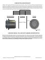
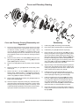
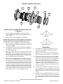
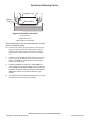
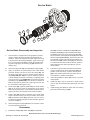
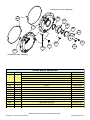
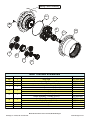
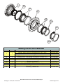
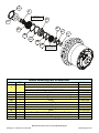
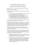
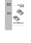
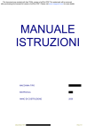
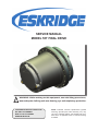
SErVIcE MAnuAL
MODEL 55T FInAL DrIVE
!
WArnInG: While working on this equipment, use safe lifting procedures,
wear adequate clothing and wear hearing, eye and respiratory protection.
THIS SErVIcE MAnuAL IS EFFEcTIVE:
S/n: 857 TO currEnT
DATE: 6-1-09 TO currEnT
VErSIOn: SM 55T-AA
nOTE: Individual customer specifications (spindle
mounting, sprocket pilot, brake assembly, etc.) may
vary from exploded drawing and standard part numbers shown. If applicable, refer to customer drawing
for details.
Lubrication & Maintenance
Gearbox nominal operating temperatures are between 122oF and 158oF. Use the chart below to determine the appropriate lubricant
viscosity for your application by choosing the highest foreseen temperature and rpm. If the gearbox is operating outside of these temperatures contact Eskridge. In applications with very low output speeds and heavy loading always choose high viscosity oils. Heavy use
applications with high continuous loading and temperatures require a plyalphaolefin synthetic lubricant. Use only EP (extreme pressure)
or API GL-5 designated lubricants. Change the lubricant after the first 50 hours of operation and at 500 hour intervals thereafter. The gear
drive should be partially disassembled to inspect gears and bearings at 1000 hour intervals.
Output RPM (n)
n<5
5<n<20
n>20
Operating Position
Temperature
50ºC (122ºF)
70ºC (158ºF)
ISO 320
ISO 460
ISO 220
ISO 320
ISO 150
ISO 220
Oil Capacity
Oil Level
Fill level
6 quarts / 5.5 liters
Drain plug
orientation
ESKRIDGE SERIAL TAG AND PART NUMBER INTERPRETATION
Note: All standard Eskridge Geardrives are issued a descriptive part number which includes information regarding
the Model, spindle style, hub mount, input spline configuration, service brake specifications, overall ratio and various available options. The serial tag , located on the cover, provides all necessary product information to identify
the final drives components. For a detailed breakdown of this information, please refer to Eskridge product specification sheets found at: http://www.eskridgeinc.com/geardrives/gearprodspecs.html
Model 55T Final Drive service manual, SM 55T-AA Page Eskridge, Inc. Olathe, KS. 913-782-1238
www.eskridgeinc.com
Cover and Planetary Gearing
5
11
25B
7
8
16C
9
10
6
16B
3
2B
25A
20C
30A
Cover and Planetary Gearing Disassembly and
Inspection
1)
Install O-ring (16C) onto bearing carrier assembly.
1)
2)
Place tertiary planet assembly (5) onto spindle splines.
3)
Install tertiary sun gear (8) and shaft coupler (11).
4) Place a thin film of oil onto the ring gear (2B) cover and
bearing carrier pilots. Place ring gear over tertiary planet
gear set and align the tertiary planet gears with the ring
gear teeth. Align ring gear retention fasteners (25B) holes
located in the bearing carrier with the threaded holes in
the ring gear. Slide ring gear over the bearing carrier pilot
and O-ring (16C). Install fasteners (25B) with blue thread
retention compound and torque to 20 ft-lbs.
5) Align secondary carrier assemblies (7) planet gears with
the ring gear and install secondary carrier. Install the secondary sun gear (8) and rotate the carrier until the carrier
spline couples with the tertiary sun gear (6).
6)
Install the primary carrier assembly (9) on the secondary carrier sun gear (8). Install the sun shaft (10) into the
shaft coupler (11) and primary gear assembly (9).
7) Install cover (3) pilot into the ring pilot (2B) then rotate
the cover until the primary gear teeth (9) mesh with the
cover gear teeth. Align the cover though holes with the
ring gear threaded holes. Place blue thread retention
compound onto the fasteners (25A). Install the fasteners
and torque them in a crisscross pattern to 37 ft-lbs.
8)
Place both plug holes in a horizontal position at approximately 2 and 9 o’clock then fill the unit with oil. Install oil
fill plugs (30A).
Disconnect brake release line from spindle. Remove hex head
cap screws retaining motor to spindle then remove motor. Take
out fasteners retaining sprocket to ring gear flange. Orient
one cover (3) drain plug (30A) in the downward position and
remove both plugs from unit. The oil will drain out more quickly
and completely if warm. Remove fasteners retaining final drive
to chassis.
2)
Remove the nine, M10 X 1.25 SHCS (25A) securing the cover
(3) to the ring gear (2B). Inspect cover O-ring (16B) and thrust
washer (20C) replace if necessary
3)
Remove sun shaft (10) then take out primary carrier assembly
(9).
5)
Remove secondary sun gear (8) and lift out secondary carrier
assembly (7).
7)
Remove two M8 X 1.25 SHCS (25B) retaining ring gear to
bearing carrier. Install two M10 X 1.5 eyebolts into ring/cover
mounting location and remove ring gear (2B). Inspect bearing
carrier O-ring (16C) and replace if necessary.
8)
Remove shaft coupler (11) and tertiary sun gear (6) and take off
tertiary carrier assembly (5).
10) Clean and inspect components, identify any individual components that require repair. Rotate planet gears to ensure planet
bearings roll freely and smoothly, replace if necessary. A bill
of materials identifying individual components and their subsequent part numbers is provided at the end of this manual
Reassembly
Model 55T Final Drive service manual, SM 55T-AA Page Eskridge, Inc. Olathe, KS. 913-782-1238
www.eskridgeinc.com
Spindle and Bearing Carrier
1
2A
20A
20B
35C
35D
16A
35A
Bearing Carrier and Spindle Disassembly and
Inspection
1)
Remove spindle lock ring (35D) using a heel bar or puller.
Don’t pry against taper roller bearing cage (20B) when removing the lock ring .
2)
Remove split ring segments (35C), and shims (35A).
New Seal
Caution: Since spindle is no longer retained, care should be
taken to avoid personal injury. Care should also be taken not to
damage spindle when it is pressed through bearing carrier.
3)
Remove bearing carrier (2A) from spindle (1) by applying a
load to the internal end of the spindle until it passes through the
internal bearing (20B).
4)
Use a gear puller to remove the outer bearing cone (20A) from
the spindle (2). If reusing the bearing cone do not pull on or
damage the bearing cage.
5)
6)
Clean and inspect inner and outer bearing cups and cones
(20A, 20B). If cups are damaged they must be replaced, drive
them out using a brass hammer and drift utilizing the bearing
knock-out notches in the bearing carrier. If a bearing cup or
cone is damaged replaced both components.
The metal face seal (16A) is design to automatically compensate for wear. The sealing band of a new seal is located at
the outer perimeter of the seal surface. As seal wear occurs
this contact band will widen and migrate towards the center
of the seal. By measuring the distance from the contact band
to the inner diameter an estimate of seal life remaining can be
obtained. If the distance between the contact band and seal
surface internal diameter is less than 50% if the overall sealing
surface width, replace seal. Below is an illustration showing the
sealing band location for a new and partially worn seal.

Partially Worn Seal
Reassembly
1)
Place spindle (1) on table with splined side up. Press
outer bearing cone (20A) onto spindle by pressing on
bearing cones inner race.
2)
Apply a thin layer of lithium or general purpose bearing
grease to the roller contact surfaces on the bearing cups.
3a) Wipe the face of each half of the metal face seal (16A)
using a lint-free wipe. No particles of any kind are permissible on the sealing surfaces. (Even a hair is sufficient to
hold the seal surfaces apart and cause a leak.) Apply a
thin film of oil on the entire seal face of one or both seals
using a clean finger or lint-free applicator. Oil must not
contact any surfaces other than the sealing faces. (If its
necessary to replace metal face seal follow steps 3b-3d If
not move onto step 4.)
3b) The seal cavities that retain the metal face seal must be
free from foreign material (oil, grease, dirt, metal chips
dust or lint particles, etc.) before installing the seal. Clean
surfaces with a lint-free wipe and a non-petroleum based
solvent.
3c) Install the seal using special installation tool shown in figure below. Mount the installation tool onto the metal seal
ring. Lightly dampen the lower half of the rubber torric with
one of the appropriate assembly lubricants outlined below.
Model 55T Final Drive service manual, SM 55T-AA Page Eskridge, Inc. Olathe, KS. 913-782-1238
www.eskridgeinc.com
Spindle and Bearing Carrier
Installation Tool
Rubber
Torric
Metal Seal Ring
Approved Assembly Lubricants*

Isopropyl Alcohol
Houghto-Grind 60 CT
Quaker® Solvo Clean 68-RAH
*Do not use Stanosol or any other liquid that leaves an oil film
or does not evaporate quickly.
3d) Push seal into housing using even pressure. When the seal
is properly seated you will feel it snap into place. Verify the
metal face seals sealing surface is parallel to the spindle or
bearing carrier housing and the torric O-ring is not budging
out.
4)
Install bearing carrier (2A) onto spindle assembly. Place bearing cone onto spindle assembly. Press on the inner race of
bearing cone (20B) using light pressure until the bearing is
seated in the bearing cup.
5)
Install shims (35A) and Load-N-Lock™ halves (35C) over
shims into the corresponding spindle groove. Then, install the
lock ring (35D) over the segments (35C). Proper spindle bearing preload will result in a rolling torque which varies between
130-170 in-lb. Add or remove shims to obtain the proper
preload.
6)
The bearing carrier and spindle subassembly service or repair
is complete at this time continue unit assembly
Model 55T Final Drive service manual, SM 55T-AA Page Eskridge, Inc. Olathe, KS. 913-782-1238
www.eskridgeinc.com
Service Brake
82
83
88
87
4
81
84A
86
84D
84C
85
84B
Service Brake Disassembly and Inspection
plate (83). Continue to install friction disks (82) then
separator plates (83) until the complete friction pack
is installed. There must always be a friction disc (82)
above and below each separator plate (83) Some units
will have a spacer (Not Shown). If the friction pack was
provided with a spacer install the spacer between the
last friction disk (82) and the piston (85). Be careful not
to contaminate the friction surfaces with dirt, grease or
fluid media other than what is specified for your particular gearbox.
1)
This final drive is equipped with a spring applied, hydraulic
release, multiple disc service brake incorporated into the
spindle. In order to disassemble the brake a light load needs
to be placed onto the backing plate (87). Apply only enough
force on the backing plate (87) to release the load the backing plate is applying to the retaining ring (88). Remove the
retaining ring.
2)
Remove backing plate (87) input shaft (4) and springs (86).
2)
3)
Apply low pressure air (20-30 PSIG) to the brake release
port while holding one hand on top of the piston (85). The
air will force the piston out of the spindle. Inspect piston Orings (84A, 84B, 84C, 84D) for signs of abrasion, extrusion
or other damage and replace if necessary. If replacing piston
O-rings, be sure O-rings (84B & 84C) are nearest each other
with backup rings (84A & 84D) to the outside. The flat side of
back-up-ring must be placed next to piston groove wall, with
the curved side contacting the O-ring.
Lubricate O-rings and bores with silicone based lube
or with mineral base oil. Gently slide Piston (85) into
spindle. Press down firmly on piston until the piston
(85) is firmly seated against the friction pack. Do not
use a hammer or mallet to install piston.
5)
Insert springs (86) into piston (85) evenly or symmetrically spaced.
6)
Install shaft (4), it may be necessary to rotate shaft in
order to align the separator plate splines with the shaft
splines.
7)
Install backing plate (87) then place load onto backing
plate and install retaining ring (88).
4)
Friction disks (82), separator plates (83) and thrust washer
(81) can be removed. Note the arrangement of the friction
disks and separator plates. Some final drives will also have a
spacer (not shown) and its position also needs recorded.
5)
Friction disks (82) should be replaced when overall stack
height of the friction pack [ spacers (not shown), friction disks
(82) and separator plates (83)] is less than 1.52 in. If the friction disks are replaced soak the new friction disks in gear box
oil prior to installation.
6)
Clean and inspect the piston (85) bores for scratches or abrasions and replace if necessary.
Reassembly
1)
Install thrust washer (81), friction disk (82) then separator
Model 55T Final Drive service manual, SM 55T-AA Page Eskridge, Inc. Olathe, KS. 913-782-1238
www.eskridgeinc.com
Disconnect Cover Assembly
16B
16D
40A
16E
3
40B
40C
25A
30A
25E
25C
25D
20C
Standard Cover Assembly
Item #
QTY
3
1
16B
16D
16E
20C
25A
25C
25D
25E
30A
40A
40B
40C
1
1
1
1
9
4
2
2
2
1
1
1
cover bill of Materials
Description
71T Cover With Disconnect
73T Cover With Disconnect
71T Cover W/O Disconnect
73T Cover W/O Disconnect
O-ring
O-ring
O-ring
Thrustwasher
SHCS M10 X 1.5 X 30MM Class 10.9
SHCS M6 X 1 X 30MM Class 10.9
SHCS M8 X 1.25 X 30MM Class 10.9
SHCS M6 X 1 X 50MM Class 10.9
Hollow Hex Plug
Disconnect Housing
Disconnect Plug
Disconnect Plunger
Part Number
55T-004-2002
55T-004-2008
55T-004-2001
55T-004-2003
01-402-0020
01-402-1003
01-402-1002
01-112-0511
01-150-2054
01-150-2050
01-150-2049
01-150-2048
01-208-0060
55T-004-1021
55T-004-1023
55T-004-1022
Model 55T Final Drive service manual, SM 55T-AA Page Eskridge, Inc. Olathe, KS. 913-782-1238
www.eskridgeinc.com
Bearing Carrier Assembly
16C
5
25B
6
11
7
2B
8
9
Item #
2B
5
6
QTY
1
1
1
7
1
8
1
9
1
10
1
11
16C
25B
1
1
2
10
Gear T rain bill of M aterials
Description
Ring Gear
Carrier Assembly - Tertiary (4.5:1)
Sun - Tertiary
Carrier Assembly - Secondary (4.46:1)
Carrier Assembly - Secondary (6.29:1)
Sun - Secondary (4.38:1)
Sun - Secondary (6.29:1)
Carrier Assembly - Primary (4.38:1)
Carrier Assembly - Primary (5.64:1)
Sun Shaft - Primary (4.38:1)
Sun Shaft - Primary (5.64:1)
Shaft Coupler
O-ring
SHCS M8 X 1.25 X 30mm C10.9
Part Number
55T-004-1035
55T-004-0103
55T-004-1008
55T-005-0105
55T-005-0102
55T-004-1029
55T-004-1009
55T-005-0104
55T-005-0101
55T-004-1030
55T-004-1010
55T-004-1020
01-402-0950
01-150-2049
Model 55T Final Drive service manual, SM 55T-AA Page Eskridge, Inc. Olathe, KS. 913-782-1238
www.eskridgeinc.com
1
16A
20A
2A
20B
35A
35C
35D
Item #
QTY
1
1
2A
16A
20A
20B
35A
35C
35D
1
1
1
1
*
1
1
bearing carrier bill of Materials
Description
Spindle, 160mm Pilot for Cartridge Motors 40cc - 60cc
Spindle, 190mm Pilot for Cartridge Motors 75cc - 90cc
Spindle, 200mm Pilot for Cartridge Motors 107cc - 125cc
Bearing Carrier, Pilot 350mm, BC 400mm, 20 X M20 X 1.5
Metal Face Seal
Tapered Roller Bearing
Tapered Roller Bearing
Shim (* Bearing Load Determines Quantity)
Split Ring - Load-N-Lock
Lock Ring - Load-N-Lock
Part Number
55T-004-4003
55T-004-4001
55T-004-4007
55T-004-3001
01-406-0010
01-103-0313
01-103-0311
55T-004-1011
55T-004-1015
55T-004-1016
Model 55T Final Drive service manual, SM 55T-AA Page Eskridge, Inc. Olathe, KS. 913-782-1238
www.eskridgeinc.com
88
4
SPRING PACK
QUANTITY VARIES WITH
GEAR BOX RATIO
87
85
83
86
82
84D
81
84C
84B
84A
Item #
QTY
4
1
81
82
83
84A
84B
84C
84D
85
86
87
88
1
*
*
1
1
1
1
1
*
1
1
FRICTION PACK
QUANTITY VARIES WITH
GEAR BOX RATIO
brake Assembly bill of Materials
Description
Brake Shaft, Input 16T DIN 5480-1
Brake Shaft, Input 18T DIN 5480-2
Brake Shaft, Input 21T DIN 5480-3
Thrust Washer
Stator (*Brake Holding Torque Determines Quantity)
Rotor (*Brake Holding Torque Determines Quantity)
O-ring
Back Up Ring
O-ring
Back Up Ring
Piston
Spring (*Brake Holding Torque Determines Quantity)
Backing Plate
Internal Retaining Ring
Part Number
55T-004-1033
55T-004-1019
55T-004-1024
01-112-0230
90-004-1742
01-288-0020
01-400-1006
01-402-0262
01-402-1007
01-400-0263
55T-004-1034
01-261-0290
55T-004-1018
01-160-0811
Model 55T Final Drive service manual, SM 55T-AA Page Eskridge, Inc. Olathe, KS. 913-782-1238
www.eskridgeinc.com