1
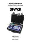
Software Version 01 - 04
1155/user/v1/150408
Vishay PM 1155 Display
IMPORTANT INFORMATION
PM Onboard Ltd design and manufacture on-vehicle weighing equipment. PM Onboard Ltd accepts no
responsibility or liability for consequences arising from any misapplication or misinterpretation of the information
contained herein. PM Onboard Ltd also reserve the right to alter system specifications at any time without notice.
PM Onboard Ltd do not accept responsibility for the structural integrity of the vehicle concerned or any part thereof.
Failure, due to poor workmanship or incorrectly installed elements, remains solely the responsibility of the installer.
Strict observance of these guidelines however, should help to ensure accurate weight measurement. The company
also reserves the right to make any amendments and alterations to this document deemed necessary.
Because of variations available in software installed in displays and intelligent junction boxes, not all features
described may be available unless the items are upgraded to the latest specification.
Vehicle Loading Stability
An indication is given as to vehicle loading error stability. This is only intended as a guide and the customer is
recommended to set a suitable value, this can be changed with experience over time.
The customer is responsible for the safe operation and legality of the vehicle during use.
Vishay PM Onboard Ltd
Design, manufacture and service of on-vehicle weighing systems.
Airedale House
Canal Road Bradford West Yorkshire BD2 1AG
United Kingdom
Tel: 01274 771177 Fax: 01274 781178
e-mail:
[email protected]
[email protected]
[email protected]
www.pmonboard.com
Document Information
The reference number for this document is: 1155/user/v1/150408
This reference filename is divided into 4 areas, these are:
pm1155
This designation is for documents covering the series 1155 display equipment supplied by
Vishay PMOnboard.
user
This designation refers to the type of equipment supplied, in this case a user manual
v1
This denotes that this documentation is version 1.
150408
This is the date on which the document was compiled. In this case the date was April 15th
2008
Copyright © Vishay PM Onboard Ltd 2008
⊳ 2 u
1155/user/v1/150408
Vishay PM 1155 Display
Contents
Important & document information............................................................................................................
2
Contents.....................................................................................................................................................
3
Vishay PM1155 introduction.......................................................................................................................
5
Accessing the available display screens....................................................................................................
7
Startup screens............................................................................................................................
8
Setting CAN or Analogue load cells............................................................................................................
9
Pheripherals................................................................................................................................
9
Changing a parameter value......................................................................................................................
11
How to identify your Vishay PM 1155 system Type.....................................................................................
13
Additional information needed.....................................................................................................
13
Definitions....................................................................................................................................
13
Order of calibration for a basic Vishay PM 1155 system...........................................................................
15
Entering the vehicle Tare weight.................................................................................................................
17
Zeroing the Tare.........................................................................................................................................
19
Zeroing an inclinometer..............................................................................................................................
21
Spanning the vehicle..................................................................................................................................
23
Setting the Net and Gross alarms..............................................................................................................
25
Axle weighing.............................................................................................................................................
27
Cell positions...............................................................................................................................
27
Axle positions..............................................................................................................................
28
Axle tares.....................................................................................................................................
28
Axle spans...................................................................................................................................
28
Axle alarm weights.......................................................................................................................
29
Twin / 5+ Air and drawbar screens..............................................................................................................
31
Calibrating...................................................................................................................................
32
Body up alarm Details................................................................................................................................
33
Setting and altering the body up alarm weight.............................................................................
34
Load / deliver screen..................................................................................................................................
35
Adding part loads to a vehicle - example......................................................................................
35
Delivering a load to three different sites - example.......................................................................
36
Load / Deliver tickets - example...................................................................................................
37
Vehicle stability...........................................................................................................................................
39
Pin number access.....................................................................................................................................
41
Optional settings........................................................................................................................................
43
Display settings...........................................................................................................................
43
Setting time and date...................................................................................................................
43
Setting a printer............................................................................................................................
44
Front panel zero..........................................................................................................................
44
User password access.................................................................................................................
45
Alarms - Manual or Auto...............................................................................................................
45
Diagnostics information - CAN mode.........................................................................................................
47
Using the display with analogue load cells...............................................................................................
51
Screen layouts and drawings.....................................................................................................................
53
Copyright © Vishay PM Onboard Ltd 2008
⊳ 3 u
1155/user/v1/150408
Vishay PM 1155 Display
Copyright © Vishay PM Onboard Ltd 2008
⊳ 4 u
1155/user/v1/150408
Vishay PM 1155 Display
Vishay PM 1155 Introduction
The PM 1155 is a display used to show information from weighing systems fitted to vehicles.
The display has available a number of main screens as standard, these are:
Time / Date
Net Weight
Gross Weight
Also available, depending on which functions are enabled are additional main screens, these are:
Axle Weights
Twin / 5 + Air
Drawbar
Load / Deliver
Stability
A number of other screens are used to setup the display and weighing system and also to show diagnostic
information.
Password (number) protection is a feature of this equipment.
Alarms are also used to show if the vehicle is out of load limits and also to show if the body is raised on a
tipper vehicle.
This display and system information is applicable to software version 01-4 onwards and junction boxes to
version 02-03 onwards.
Copyright © Vishay PM Onboard Ltd 2008
⊳ 5 u
1155/user/v1/150408
Vishay PM 1155 Display
Copyright © Vishay PM Onboard Ltd 2008
⊳ 6 u
1155/user/v1/150408
Vishay PM 1155 Display
Accessing the Available Display Screens
The various screens and on-screen options are accessed by using the display buttons A - E and observing
the changes on the LCD display screen F:
Button - A
This is on the left of the display and is used to power ON or
power OFF the display.
NOTE:
The display is often set to come ON when the ignition is turned on.
Button - B
This button is used to access menus and select menu items.
Button - C
This button is used to scroll up an on-screen list and increment selected values in Edit.
Button - D
This button is used to scroll down an on-screen list and decrement selected values in Edit
Button - E
This button is used to accept changes to screens or parameters and exit the screen.
LCD display - F
For display of Gross, Net menus etc.
Copyright © Vishay PM Onboard Ltd 2008
⊳ 7 u
1155/user/v1/150408
Vishay PM 1155 Display
Startup Screens
When the display is first powered up it will show a screen with the PM logo, display type and the software version,
as shown here:
This is followed by a P.O.S.T. (Power On Self Test) screen while the display checks various parameters.
When this process is complete the first of the main information screens appear.
This can be one of a number of different ‘Main’ screens available, depending on the options setup in the display.
These are always available when the display is on. Use the
The standard options available are:
button to scroll through the available main screens.
Net Weight
Gross Weight
Time / Date
See page 43 for details
Additional Available Startup Screens
Other ‘Main’ screens can appear here if the appropriate options are turned on from within Setup etc, these are:
Axles
See page 27 for details
Load / Deliver See page 35 for details
Twin / 5 + Air
See page 31 for details. This option cannot be selected at the same time as Drawbar.
Drawbar
See page 31 for details. This option cannot be selected at the same time as Twin / 5+ Air.
Stability
See page 39 for details
Copyright © Vishay PM Onboard Ltd 2008
⊳ 8 u
1155/user/v1/150408
Vishay PM 1155 Display
Setting CAN or Analogue Load Cells
1.
In the Time / date main screen press the Menu
button
2.
Press
3.
Press the
button to go into the Setup menu
4.
Press the
to go to the Vehicle Config option
5.
Press the
button to select
6.
This option should be pre-set to CAN load cells, if not scroll through the available options using the
button to select the Setup option.
button to select
7.
Press the Exit
button 3 times to return to the main screens
NOTE:
If using peripherals (511 remote, packer switch etc) that may be analogue then set the display to’ CAN
AUTO’ in stead of ‘CAN’ in step 6.
Copyright © Vishay PM Onboard Ltd 2008
⊳ 9 u
1155/user/v1/150408
Vishay PM 1155 Display
Copyright © Vishay PM Onboard Ltd 2008
⊳ 10 u
1155/user/v1/150408
Vishay PM 1155 Display
Changing a Parameter Value
Where an on-screen parameter has a changable value against it and the value has to be changed then a
standard method can be used to alter the value regardless of which screen is used.
.
A typical example of this would be the NET ALARM screen shown here:
To Change a Parameter Value
The selected parameter is shown by the long grey bar on the parameter and value.
The value shown here is 1050kg.
1.
To change this press button
(Edit). This will clear the long bar and highlight the first changable
value, as shown in the screen below:
2.
Use buttons
3.
To move to the next value in line press button
4.
Once the required value is fully changed press button
5.
Press button
Copyright © Vishay PM Onboard Ltd 2008
&
to alter the original value to the required value.
and repeat as for line 2.
, this will show the new value.
again to leave the screen.
⊳ 11 u
1155/user/v1/150408
Vishay PM 1155 Display
Copyright © Vishay PM Onboard Ltd 2008
⊳ 12 u
1155/user/v1/150408
Vishay PM 1155 Display
How to identify your Vishay PM 1155 System type
This page shows you how to identify the type of PM 1155 system fitted to your vehicle and to calibrate that
system.
How to Identify:
1.
Look under the vehicle at the load cells:
If the cable from the load cells are about 18” - 20” long to a connector then the load cells are
CAN types.
If the cables are much longer, running directly from the load cell to the junction box and there are no
plugs fitted, then the load cells are the Analogue types.
2.
Look at the type of junction box fitted:
In most instances this is located near the centre of the chassis on the inside, all the load cell cables
run to this item.
If the junction box is yellow then this is a CAN junction box.
If the junction box is grey with a red label then this is an Analogue junction box.
NOTE:
In certain cases the vehicle may have been painted after the weighing system was fitted, in these
cases scrape a small amount of paint from the junction box to determine the base colour.
3.
Identify the type of vehicle:
Setup and calibration will vary slightly depending on the type of vehicle that the weighing system is
fitted to, the main types of vehicle are:
Standard - this is a normal heavy goods vehicle using 2 or more axles. This type can be a normal
body type, a roll on - roll off type or a refuse vehicle, etc., 1 junction box and up to 8 load cells.
Tipper - this is similar to the above but the body can be raised to remove the load.
5th Wheel and Air - this type uses a separate prime mover cab to pull separate trailers using a 5th
wheel coupling and air suspension on the trailer. Only available with 4 or 8 load cell systems.
Drawbar - this type has a ring and pin type coupling on the prime mover (cab or vehicle) to pull a
separate trailer. Only available with 4 or 8 load cell systems.
Additional information you may need:
When calibrating the PM 1155 system there are additional pieces of information you may need:
1.
.
2.
If you are using Axle Weighing to weigh the load on individual axles you will need to know the
number of axles fitted to the vehicle, i.e. one front + one rear, one front + two rear, two front + two
rear, etc
The Tare and Gross weight of the vehicle - these can be obtained during the calibration process
using a weighbridge etc.
Definitions
Tare Weight
The weight of an empty vehicle but including the weight of a full fuel tank and the weight of the driver.
Net Weight
The weight of the maximum load that the vehicle is legally allowed to carry. This is the Gross weight less the
Tare weight.
Gross Weight
The maximum legally allowed overall weight of the vehicle, i.e. the Tare weight plus the Net weight.
Copyright © Vishay PM Onboard Ltd 2008
⊳ 13 u
1155/user/v1/150408
Vishay PM 1155 Display
Order of calibration - Examples
Example 1
This example uses CAN load cells and Weigh Mode set to ‘Standard’.
Use with the ‘Order of calibration for a basic Vishay PM 1155 system’ on the next page.
Tare weight - 2000kg
See step 9.
The main screens will now show:
Net - 0kg
Gross - 2000kg
Net (load weight) added - 20,000kg - then span.
See step 12.
The main screens will now show:
Net - 2000kg
Gross - 22 0000kg
Example 2
This example uses CAN load cells and Weigh Mode set to ‘Twin/5 +Air’ (or ‘Drawbar’)
Use with the ‘Order of calibration for a basic Vishay PM 1155 system’ on the next page.
Front Tare weight - 1200kg, rear Tare weight - 800kg
As step 9 but set Front and Rear Tares
instead of an overall total Tare weight.
The main screens will now show:
Net - 0kg
Gross - 2000kg
Twin/5+Air - 1200kg F / 800kg R
Net (load weight) added - 20,000kg - then span.
As step 12. but set front Tare to 8000kg and rear
Tare to 12000kg.
The main screens will now show:
Net - 20000kg
Gross - 22 0000kg
Twin/5+Air - 9200 F / 12800 R
Copyright © Vishay PM Onboard Ltd 2008
⊳ 14 u
1155/user/v1/150408
Vishay PM 1155 Display
Order of calibration for a basic Vishay PM 1155 System
With all the weighing equipment fitted and the required information known from the initial checks the vehicle
and weighing system can be calibrated. A sequence for carrying this out is below. Use this in conjunction
with the examples on the previous page.
Power - on screen Items 1 - 3.
1.
Power the system up - the weighing system will be powered up when the ignition is turned
on in most cases, an exception to this could be a tipper vehicle.
2.
Watch the opening P.O.S.T. (Power On Self Test) screens carefully, these will show that
the load cells and junction box have been detected correctly.
3.
On an initial calibration a message will be shown saying that new load cells have been
detected.
4.
If the vehicle is a tipper then raise the body until clear of the guides, ensure the body does
not catch anywhere.
5.
Go to the Main Menu screen - set the time and date and then return to the Main screen.
6.
Go to Vehicle Configuration.
7.
Select the load cell type fitted, CAN or Analogue.
Calibrate Zero Items 8 - 10
The steps from here must be carried out on a weighbridge. See also page 19 for full details.
8.
With the EMPTY vehicle on a weighbridge enter the Tare weight (2000kg in example) and
then zero the vehicle.
9.
Select Calibrate.
10.
With the vehicle as level as possible zero the inclinometer.
Span the vehicle Items 11 - 16.See also page 23 for full details.
11.
Exit to the Main screens, this should in most cases be the NET screen, if not go to the
NET screen.
12.
LOAD THE VEHICLE - as near to the maximum allowed load weight as can be managed
(20,000kg in the example).
13.
Go to the Main screens again.
14.
Go to Setup.
15.
Go to Calibrate.
16.
With the vehicle on a weighbridge span the display - Minimum weight (Tare) to Maximum
weight (Gross) - see page 23 for more information.
17.
Customise any other settings to your own requirements, i.e axle weighing, twin / 5 + air, drawbar,
password etc.
18.
Set the alarms - set the NET alarm to about 100kg less than the weight of the load carried (NET),
i.e. if the load carried is 20000kg (20 Tonnes in example) then set the alarm to 19900kg (19 Tonnes, 900 kg).
Copyright © Vishay PM Onboard Ltd 2008
⊳ 15 u
1155/user/v1/150408
Vishay PM 1155 Display
Copyright © Vishay PM Onboard Ltd 2008
⊳ 16 u
1155/user/v1/150408
Vishay PM 1155 Display
Entering the Vehicle Tare weight
The Tare weight of a vehicle is the weight of the empty vehicle, but including the weight of a full tank of fuel
and the weight of the driver.
This page is used when the ‘Axles’ setup option is not used, i.e. the Tare weight applies to the whole vehicle
NOT the Tare weight of each axle.
To set the Tare weight of each axle see the ‘Axle Weighing’ page.
With vehicle as above drive the vehicle onto a weighbridge and obtain the Tare weight.
In the display go to: Menu - Setup - Vehicle Config - Tare Weight by pressing the
button until the
Time / Date screen can be seen, then pressing the
button to get the Menu screen.
Press the
button to get Setup, followed by the
button to open the Setup screen.
Press the
button to go to Vehicle Config, followed by the
Press the
button to scroll to the Tare Weight option.
button to open the screen.
Set the Tare weight to the value shown on the weighbridge ticket using the method shown on the ‘Changing
a Parameter Value’ screen. See page 11 for full details.
Press
4 times to return to the main screen.
NOTE:
You can also obtain the Tare weight of a vehicle using weighpads under each wheel, if available.
Copyright © Vishay PM Onboard Ltd 2008
⊳ 17 u
1155/user/v1/150408
Vishay PM 1155 Display
Copyright © Vishay PM Onboard Ltd 2008
⊳ 18 u
1155/user/v1/150408
Vishay PM 1155 Display
Zeroing the Tare
Body
With vehicle empty go to: Menu - Setup - Calibrate by pressing the
can be seen, then pressing the
Press the
button to get the Menu screen.
button to get Setup, followed by the
Press the
button to go to Calibrate, followed by the
Zero will be highlighted.
Press the
button until the Time / Date screen
button to open the Setup screen.
button to open the screen.
button The screen shows “Are you sure ? Yes / No”. Press Yes, (
button).
The screen shows “Zero OK” then returns to the previous screen.
Press
3 times to go to the main screen.
Copyright © Vishay PM Onboard Ltd 2008
⊳ 19 u
1155/user/v1/150408
Vishay PM 1155 Display
Copyright © Vishay PM Onboard Ltd 2008
⊳ 20 u
1155/user/v1/150408
Vishay PM 1155 Display
Zeroing an inclinometer (CANbus only)
1.
In the Time / Date main screen use the
2.
Use
to select Setup
3.
Use
to open Setup screen
4.
Use
to go to Calibrate option
5.
Use
6.
Use
to go to Zero Inclinometer
7.
Use
to select, confirmation screen opens
8.
Use
to select Yes, screen closes
9.
Press
3 times to go back to main screen
Copyright © Vishay PM Onboard Ltd 2008
to open the Menu screen
to open option screen
⊳ 21 u
1155/user/v1/150408
Vishay PM 1155 Display
Copyright © Vishay PM Onboard Ltd 2008
⊳ 22 u
1155/user/v1/150408
Vishay PM 1155 Display
Spanning the Vehicle
The idea of spanning a vehicle is to take the Tare (empty vehicle) weight from the maximum (gross) weight
for the vehicle and to input the weight left (Net or load weight) into the display so that the display can
typically use the Tare weight as EMPTY and the Gross weight as FULL when working out the amount of load
weight actually in the vehicle at a given point in time.
Example:
Tare weight = 25000kg
Gross weight = 45000kg
Gross weight less Tare weight = Net weight:
45000kg - 25000kg = 20000kg
Therefore Net (load) weight = 20000kg
When the vehicle is spanned the display would use the 20000kg Tare weight as the net span weight.
Load vehicle to as near full load as possible (20000kg).
1.
In the Time / Date main screen use the
2.
Use
to select Setup
3.
Use
to open Setup screen
4.
Use
to go to Calibrate option
5.
Use
6.
Go to Span with the
to open the Menu screen
to open option screen
button and then press the
button. Screen shows “Net Span Weight”
and “Calibrate”. Net Span Weight should be selected by pressing
To alter weight press
values and
Copyright © Vishay PM Onboard Ltd 2008
.
button, first figure will be highlighted. Alter figure using
&
buttons to alter
button to move along figure until correct value is reached (in this instance 20000kg).
⊳ 23 u
1155/user/v1/150408
Vishay PM 1155 Display
Press
to go to the previous screen.
Press the
button to go to the “Calibrate” option followed by the
“Are you sure ? Yes / No”, with a YES next to the
Press Yes (
Press
button to select. The screen will say
button and a NO next to the
button.
button), screen shows “Calibrated OK”.
4 times to go to the main screen.
Copyright © Vishay PM Onboard Ltd 2008
⊳ 24 u
1155/user/v1/150408
Vishay PM 1155 Display
Setting the NET and GROSS Alarms
1.
In the main Time / Date screen use the
2.
Use the
to go to the Setup option
3.
Use the
to select the option
4.
The Setup screen will open with the Alarms option selected
5.
Use the
to select the option
6.
Use the
to select the NET or GROSS options as required
7.
See 'Changing a parameter Value' for how to alter the values. See also page 11.
8.
When values altered to your requirements press the
screen
Copyright © Vishay PM Onboard Ltd 2008
⊳ 25 u
to select the menu screen
3 times to return to the main
1155/user/v1/150408
Vishay PM 1155 Display
Axle locations and load cell distances record
Use this page to record the axle and load cell distance settings used for a vehicle.
Copy this page as required for additional or new vehicles.
Axle Locations
Axle Distances
Axle Distances - in Centimetres
Vehicle Identification:
Axle No.
1
2
3
4
Distance from
front bumper
1
2
3
1
Bulkweigh
Type Vehicle
Tipper Type
Vehicle
Load Cell Distances
Load Cell Distances - in Centimetres
Vehicle Identification:
Axle No.
1
2
3
4
Distance from
front bumper
Copyright © Vishay PM Onboard Ltd 2008
⊳ 26 u
1155/user/v1/150408
Vishay PM 1155 Display
Axle Weighing
When the Axle options are turned on :
1.
In the main Time / Date screen use the
button to select the menu screen
2.
Use the
button to go to the Setup option
3.
Use the
button to select the option
4.
The Setup screen will open
5.
Use the
6.
Use the
button to select the Weigh Mode option
7.
Use the
button to scroll through the available options and select Axle
button to select the Vehicle Config option and then press
.
6.
Various axle related items appear in the screen list, these are:
Number of axles
Cell positions
Axle positions
Axle tares
Axle spans
The number of axles on the vehicle is added using the
to select the ‘Number of Axles’ option and then
the
button to scroll through the options.
The number of axles can be set to 2, 3 or 4.
You now need to set the distances of the load cells and axles from a datum - in this case the front face of the
front bumper. (see diagrams following).
Cell Positions
Scroll down to Cell Positions with the
button and select with the
button.
This screen shows each axle location with an associated distance in Centimetres from the datum.
Each distance can be altered as for the standard parameter screens.
Measure each distance on the vehicle and record the details - a table is provided later in the manual.
Photocopy the table page if more than one vehicle is to be recorded.
When all measurements are correct press the
Press the
button to leave the screen.
button to go to the next axle option - Axle Positions
1
2
3
1
Bulkweigh Type Vehicle Cell Positions
Copyright © Vishay PM Onboard Ltd 2008
⊳ 27 u
Tipper Type Vehicle Cell Positions
1155/user/v1/150408
Vishay PM 1155 Display
Axle Positions
This screen shows each axle location with an associated distance in Centimetres from the datum.
Each distance can be altered as for the standard parameter screens
Measure each distance on the vehicle and record the details - a table is provided later in the manual.
Photocopy the table page if more than one vehicle is to be recorded.
1.
Use the
button to select the option
2.
3.
The Axle Positions screen will open, with a separate line for each axle selected previously.
Alter the figure for each axle position - see standard parameter screens.
When all measurements are correct press
Press the
to leave the screen.
arrow button to go to the next axle option - Axle Tares.
Vehicle Axle Positions
Axle Tares
Use the
button to open the Axle Tares screen.
This screen shows the Tare weight for each axle location and is similar to the Axle Positions screen.
1.
Use the
button to select the option.
2.
3.
The Axle Tares screen will open, with a separate line for each axle selected previously.
Alter the figure for each axle Tare weight - see standard parameter screens for method.
When all measurements are correct press
Press the
to leave the screen.
arrow button to go to the next axle option - Axle Spans
Axle Spans
Use the
button to open the Axle Spans screen.
This screen shows the Span weight for each axle location.
1.
Use the
button to select the option.
2.
3.
The Axle Spans screen will open, with a separate line for each axle selected previously.
Alter the figure for each axle span weight - see standard parameter screens for method.
When all measurements are correct press
Copyright © Vishay PM Onboard Ltd 2008
to return to the Setup screen.
⊳ 28 u
1155/user/v1/150408
Vishay PM 1155 Display
Axle Alarm Weights
1.
Use the
button to go to the Alarms option.
2.
Use the
button to select the option.
3.
use the
button to scroll down the list of options, added to the list will be an option for each axle
that has been added, (Axle 1, Axle 2 etc.).
A weight is shown against each axle location, this is the weight on that axle at which the alarm will sound.
Highlight each axle in turn and edit the weight as for the standard parameters screen.
When all measurements are correct press
three times to go to the main screens.
Main Screen
In the main screens there will be a new screen available, press the
screen.
button to go to the new Axles
This has the current weight, in Tonnes, shown for each axle.
To activate or de-activate the alarm facility press the
alarm is activated.
button, an icon
will appear on screen when the
With the alarm ON, when the weight on an axle exceeds the preset weight the alarm will sound.
To print out the weights on each axle press the
Copyright © Vishay PM Onboard Ltd 2008
⊳ 29 u
button.
1155/user/v1/150408
Vishay PM 1155 Display
Copyright © Vishay PM Onboard Ltd 2008
⊳ 30 u
1155/user/v1/150408
Vishay PM 1155 Display
Twin / 5 + Air and Drawbar Screens
Use the Menu function in the Time / Date screen to access settings.
To access any Settings screens you must have password access, unless the display has not been setup
previously.t
Setting Up the display with Twin / 5 + Air
NOTES:
1.
These instructions show how to setup and use the Twin / 5 + Air options but the method is the same
for the ‘Drawbar’ option, just select ‘Drawbar’ instead of ‘Twin/5 + Air’.
2
These options are ONLY available with either 4 or 8 load cells fitted and is NOT available when 6
load cells are fitted.
Setting Up Display:
1.
In the Time / Date screen press the
button.
2.
Use the
3.
Press the
4.
Use the
5.
Press the
6.
Use the
Button to scroll down to the Weigh Mode option.
7.
Use the
Button to toggle between the available options and select Twin / 5 + Air.
8.
Press the
button 3 times to go back to the main screens.
9.
Press the
seen.
button to toggle through the main screens until the Twin / 5 + Air screen can be
Button to scroll down to the Setup option.
Button, the Setup screen will open.
Button to scroll down to the Vehicle Config. option.
Button, the Vehicle Config. screen will open.
Twin / 5 + Air Screen
This shows the overall gross weight (weight of the load and the vehicle combined) of the vehicle and the
percentage of that weight on the front and rear axles.
The weights can be shown either as a weight in Kilogrammes, as in this screen,
Copyright © Vishay PM Onboard Ltd 2008
⊳ 31 u
1155/user/v1/150408
Vishay PM 1155 Display
or as percentages, as in this screen.
Options Available in the Twin / 5 + Air Screen:
Alarm
An alarm symbol i
s shown in the top left hand corner. This can be turned on or off using the
button.
% or Kg
The display can be toggled between percentages or Kilogrammes using the
button. If Kilogrammes are
chosen then % will be shown next to the button. If percentages are chosen then Kg will be shown next to the
button.
Print
The
button can be pressed to print out the weights onto a ticket.
The word ‘Printing’ will appear briefly at the base of the screen.
Exiting
The
button closes the screen and moves you to the next main screen available.
Calibrating Twin / 5+Air
This example uses CAN load cells and Weigh Mode set to ‘Twin/5 +Air’ (or ‘Drawbar’)
Use with the ‘Order of calibration for a basic Vishay PM 1155 system’ on the next page.
This repeated from page 16
Front Tare weight - 1200kg, rear Tare weight - 800kg
As step 9 but set Front and Rear Tares
instead of an overall total Tare weight.
The main screens will now show:
Net - 0kg
Gross - 2000kg
Twin/5+Air - 1200kg F / 800kg R
Net (load weight) added - 20,000kg - then span.
rear
As step 12. but set front Tare to 8000kg and
Tare to 12000kg.
The main screens will now show:
Net - 20000kg
Gross - 22 0000kg
Twin/5+Air - 9200 F / 12800 R
Copyright © Vishay PM Onboard Ltd 2008
⊳ 32 u
1155/user/v1/150408
Vishay PM 1155 Display
Body Up Alarm Details
Purpose:
This alarm sounds when a tipper body is raised.
To access the Body Up Alarm screen from the main Time / Date screen:
1.
Press the
button to go to the main menu.
2.
Press the
button to go to the Setup option.
3.
Press the
button to open the option screen, Alarms is highlighted.
4.
Press the
button again to open the Alarm option, the Alarms screen will open.
5.
Press the
6.
Press the
button to go to the Body Up option.
button to open the Body Up Alarm screen.
The alarm can be set to On or Off using the
symbol
button. An alarm symbol
and a vehicle with its body up
will be shown on screen if On is selected - see screen below:
NOTE:
Pressing the
button will also turn on the Stability option in the Alarms screen.
The Body Up alarm will beep at intervals. Pressing the
With the vehicle body down, pressing the
of the screen.
Copyright © Vishay PM Onboard Ltd 2008
button will turn off the beep.
button will show the message “Body Down” at the bottom righ
⊳ 33 u
1155/user/v1/150408
Vishay PM 1155 Display
The Body Up alarm point will be set to zero:
Example:
If the body up alarm is ON and the weight is set to -500kg then if the body is raised the system will detect
the decrease in weight and when this reaches approximately the start weight the alarm will sound.
Press the
button 4 times to return to the main screens.
Body Down option - main screen
Set the alarm with the vehicle empty and the body down.
Press the
button, the alarm and vehicle symbols will appear and the alarm will be on.
Setting and altering the Body Up alarm weight.
NOTE:
In most cases the default setting can be left as supplied.
1.
Press the
button to go to the main menu.
2.
Press the
button to go to the Setup option.
3.
Press the
button to highlight the Settings option
4.
Press the
button to open the option screen
5.
Press the
button to go to the Zero Limit option
6.
Press the
button again to open the option, the figure can now be altered as for a Standard
Parameter screen.
7.
Press the
Copyright © Vishay PM Onboard Ltd 2008
button 3 times to return to the main screens.
⊳ 34 u
1155/user/v1/150408
Vishay PM 1155 Display
Load / Deliver Screen
This feature is designed to allow a user to fully load up a vehicle and then drop off parts of the total load with
different customers. The weight of the part load can be printed out.
To Setup and Use Load / Deliver:
1.
In the Time / Date main screen press the
2.
Press the
3.
Press the
4.
Use the
5.
Press the
6.
Use the
7.
Use the
8.
Press the
9.
Use the
button to open the main menu.
button to highlight the Setup opotion.
button to open the option.
button to scroll to and highlight the Settings option.
button to open the option.
button to scroll down to the Load / Deliver option.
button to toggle the option between ON and OFF as required.
button 3 times to return to the main screens.
button to scroll to the Load / Deliver screen shown here:
Adding part loads to a vehicle - example
These details assume that the Tare, Net Weight and Gross Weight are set.
The example assumes a net weight of 20 000kg, and a gross weight of 50 000kg.
There are three part loads: 7000kg, 8000kg and 5000kg, giving a total of 20 000kg
The Net Weight and Gross Weight should appear on their respective main screens.
1.
2.
Press the
button.
Load the vehicle with the first part load (7000kg). The weight will be shown on the screen.
Press
to print the first weight on the load ticket.
3.
Press and hold the
4.
Load the second part (80000kg) and zero. Press
5.
Load the third part (5000) and zero. Press
6.
Access the Load / Deliver main screen using the
7.
Press the
8.
Press the
button again, a load figure will appear and the ALARM at the top of the screen will
change to EDIT.
9.
Print out the ticke with the
Copyright © Vishay PM Onboard Ltd 2008
button until the weight resets to zero.
button, the alarm symbol
to print the second weight on the load ticket.
to print the third weight on the load ticket..
button.
will disappear.
button.
⊳ 35 u
1155/user/v1/150408
Vishay PM 1155 Display
Load / Deliver continued
The figure shown on the previous screen (5000kg) is the amount at which the alarm will sound.
For this example set the figure to the first part load weight of 7000kg.
1.
Press the
button until the word ‘Edit’ appears at the top left of the screen and the load figure of
5000kg is highlighted.
2.
Press the
3.
Use the
button to move along the figure and the
first part of the load required (7000kg)
4.
Press
button again and the figure will have the first digit highlighted.
and
buttons to alter the figure to suit the
twice to return to the first screen.
The weights for the second and third part loads are set in the same manner.
The accumulated load is shown on the screen.
Delivering a load to three different sites - example
1.
2.
3.
4.
5.
6.
These details assume that the Tare, Net Weight and Gross Weight are set.
The example assumes a net weight of 20 000kg, and a gross weight of 50 000kg.
There are three part loads: 7000kg, 8000kg and 5000kg, giving a total of
20 000kg
The Net Weight and Gross Weight should appear on their respective main screens.
Load the total delivery weight onto the vehicle (20000kg)
On arrival at the first delivery site set the alarm to the first weight (7000kg) - see previous example.
7.
8.
Press the
(ON-SITE) button, this will print out the load ticket header and time etc.
Deliver the first part of the load. The alarm will sound when the set weight is reached.
9.
Press and hold the
10.
Press the
button, the weight of the first part of the load will be added to the ticket. Pass over
the weight ticket.
11.
Press the
Copyright © Vishay PM Onboard Ltd 2008
button until the weight on screen is zeroed.
(OFF-SITE) button.
⊳ 36 u
1155/user/v1/150408
Vishay PM 1155 Display
Load / Deliver continued
To deliver the rest of the load move to the next delivery point.
Reset the alarm to the weight required for the second delivery (8000kg).
Repeat parts 7 to 11.
Reset the alarm to the weight required for the third delivery (5000kg).
Repeat parts 7 to 11.
Example Load / Deliver Tickets:
1.
If Tare is Zero - no gross.
2.
Net and Gross weights used.
Copyright © Vishay PM Onboard Ltd 2008
⊳ 37 u
1155/user/v1/150408
Vishay PM 1155 Display
Copyright © Vishay PM Onboard Ltd 2008
⊳ 38 u
1155/user/v1/150408
Vishay PM 1155 Display
Vehicle Stability
An indication of vehicle stability can be shown on a main screen if this option is setup.
To setup the stability option:
1.
In the Time / Date screen press the
button to open the main menu.
2.
Use the
3.
Press the
4.
Use the
5.
Press the
6.
Use the
6.
A loudspeaker icon
7.
Press the
button to return to the Alarms screen, the Stability option will now be available and
should already be selected.
8.
Use the
button to select the Setup option.
button to open the already selected Alarms option.
button to select the Body Up option.
button to open the Body Up option
button to select the ON / OFF option in the top right corner of the screen.
and a vehicle with a raised body icon
will appear on the screen.
button to toggle the stability option ON or OFF as required - see screen below.
The stability screen, shown here:
has a picture of a vehicle in the centre, this picture tilts to show the direction of any vehicle lean.
Also on screen is an indication of the amount of lean in degrees and as a percentage of the total allowed
lean, with an arrow to show the direction.
When the vehicle leans more than a set amount the alarm will come on to warn the user.
The amount of lean before the alarm comes on is pre-set and cannot be altered.
At the right hand side of the screen is an indication of the net weight in the vehicle.
Copyright © Vishay PM Onboard Ltd 2008
⊳ 39 u
1155/user/v1/150408
Vishay PM 1155 Display
Copyright © Vishay PM Onboard Ltd 2008
⊳ 40 u
1155/user/v1/150408
Vishay PM 1155 Display
PIN Numbers Access
PIN Numbers
A PIN number is required to access the Setup screens etc.
There are separate PIN numbers allowed for the User and the Manager.
The Manager can access all available options.
The user can only access Alarms, on the main menu and only if User Alarms are turned on in the Pin Access
screen.
Default PIN Number
The default PIN number is 0000 (four zeros) and ican be left unaltered by the PM Onboard engineer or
changed to something different. This number is changed as below:
Entering New PIN Numbers
To enter a new Manager PIN number:
1.
From the Time / Date screen use the
button to open the main menu.
2.
Use the
3.
Select “ Set Manager PIN” with the
4.
Enter the required PIN number using the
button to open the PIN Access option.
button. A new screen will open:
button to move along the number and the
or
arrow button to alter the individual figures.
5.
When the new number is on screen press the
5.
select YES using the
arrow button. A confirmation screen will open:
button. The password is now set.
PIN Control
To enter a new User PIN number highlight the “Set User PIN” option and follow the same process as for the
Manager PIN.
Highlight the PIN Control option on the screen with the
buttons and press the
the option to USER / MANAGER. This allows the use of PIN controls with the display.
button to toggle
User Alarms
To allow the user to access the user alarm options of the display highlight the “User Alarms” option on the
screen with the
buttons and use the
button to toggle to YES.
Turning this option to YES means the user can alter the alarm settings on the display main screens. Turning
this option OFF means that the user cannot alter the alarm settings.
Copyright © Vishay PM Onboard Ltd 2008
⊳ 41 u
1155/user/v1/150408
Vishay PM 1155 Display
Copyright © Vishay PM Onboard Ltd 2008
⊳ 42 u
1155/user/v1/150408
Vishay PM 1155 Display
Optional Settings
Display Settings
To go to these options:
1.
In the Time / Date screen press the
Display option will already be selected.
2.
Press the
3.
Use the
button to open the main menu options, the
button to open the display option.
and
buttons to move between the various options.
This screen deals with the general setup parameters affecting the display. The options are:
1.
Contrast.
To alter the contrast of the screen use the
controlling value between 1 and 8.
button to increase / decrease the
2.
Power on screen.
This shows which information screen will be displayed initially.
The options are: NET Weight or GROSS Weight.
3.
Key bleep.
This can be set to Off or On by using the
When all these options are set press the
button.
button twice to go back to the main screens.
Setting the time and date
1.
2.
In the Time / Date main menu screen press the
Press the down arrow to go to the Setup option
3.
Press the
4.
Use the
5.
6.
Press the
to open the option
Highlight the figures requiring changing and change to the new date / time - see 'Changing a
Parameter Value'
Turn daylight saving On as required - only used in the UK.
7.
to open the main menu
to open the option
button to go to the Set Time / Date option
8.
When all set press the
'Set Clock - Yes / No'
9.
Press the
button to OK changes (or the
10.
Press the
button twice to return to the main screens
11.
Press the
button to go to the main Time / Date screen to check the settings
Copyright © Vishay PM Onboard Ltd 2008
button to save changes, a new screen will open saying
⊳ 43 u
button to discard).
1155/user/v1/150408
Vishay PM 1155 Display
Setting a printer
The Vishay PM 1155 weighing system can use a variety of printers, thermal or impact.
In most cases a 'Sprint' thermal printer will be used
The default printer settings are:
9600 Baud Rate
Handshake Off
Print header On
These settings will be OK to use without alteration.
If an impact type printer is used in a situation requiring large data transfer rates then the handshaking can be
turned on, to do this:
1.
In the Time / Date main menu screen use the
to select the menu
2.
Use the
button to select the Setup option
3.
Use the
button to select the Outputs option
4.
Use the
to open the Outputs screen, the screen opens with the Serial Output option selected
5.
Use the
to open the option
6.
Use the
button to select the Handshake option
7.
Use the
to select On
Print Header
The print header appears at the top of a printer load weight ticket and by default is: PM Onboard Ltd and the
PM service telephone number.
To change the print header
1.
In the Serial Output screen (item 5 in the list above) use the
the 'Change Print Header' option
button to scroll down the list to
2.
Use the
3.
Select and change the existing text - see 'Changing a Parameter Value' for how to do this, there is a
maximum of 64 characters including spaces available.
4.
When the text has been changed to your requirements then press the
to the main screens
button to open the option
button 5 times to exit out
Front Panel Zero
This option gives you the ability to zero the Net weight main screen. This has three options: On, Off, Single.
OFF:
This option is not available.
ON:
The word Zero appears in the bottom corner of the main ‘Net Weight’ screen.
Press the
button and hold down for 3 to 5 seconds, ‘Zero OK’ will appear briefly on
the screen and the Net weight will be zeroed.
This operation can be carried out as many times as possible.
SINGLE:
The operation is the same as ‘ON’ but can only be carried out once.
To activate Front Panel Zero:
In the Time / Date main screen press the
button to open the main menu.
Use the
button to go to the ‘Setup’ option and the
Use the
button to go to the ‘Settings’ option and the
Use the
button to go to the ‘Front Panel Zero’ option.
Use the
button to select either OFF, ON or Single.
Press the
button to open this.
button to open this.
button 3 times to return to the main screens.
Copyright © Vishay PM Onboard Ltd 2008
⊳ 44 u
1155/user/v1/150408
Vishay PM 1155 Display
User Password Access
If you have user password access you will have access to an extra item on the Menu screen.
These are the user alarms.
Select the Alarms option with the
button and press the
button, the Alarms screen will open.
Here you can set the operating mode to Auto or Manual, set the Gross and Net weights at which the alarm will
sound and set the Body Up alarm threshold.
Use the
button to select an option. Use the
decrease the weights.
and
buttons to move between options and to increase or
Pressing Body Up will open the Body Up Alarm screen:
This shows the (negative) weight at which the body up alarm will sound.
Use the
button to turn the alarm on or off - when turned on
symbols will apear on the screen.
Alarms - Manual or Auto
In the Setup - Alarms screen the alarms can be toggled between Manual and Auto:
Manual The alarm sounds when the weight is over the set weight.
The alarm goes off when the weight is less than the set point and will not go back on if the weight is
increased again. The alarm symbol disappears.
Auto
The alarm sounds when the weight is over the set weight.
The alarm goes off when the weight is less than the set point and goes back on if the weight is
increased again. The alarm symbol will be back on the screen.
Turning the Display Off
Press the
button once to turn off the display.
Copyright © Vishay PM Onboard Ltd 2008
⊳ 45 u
1155/user/v1/150408
Vishay PM 1155 Display
Copyright © Vishay PM Onboard Ltd 2008
⊳ 46 u
1155/user/v1/150408
Vishay PM 1155 Display
Diagnostics Information - CAN mode
When the option is selected this screen opens in the first of ten screens. These screens are only for
information and cannot be altered.
Use the
or
buttons to access the other diagnostic screens available.
Use the PRINT facility (
1.
2.
3.
4.
5.
6.
7.
8.
9.
10.
11.
button) from any screen to print out a list of parameters shown in diagnostics.
System
J/box configuration
J/box Software version
Adjusted Net
Raw Net
Millivolts
P.I. Value
P.I. Percent
Serial Number (of each load cell)
Software Version (of each load cell)
Inclinometer
1
System Screen
This screen shows the battery voltage, the excitation voltage and the installed software serial
number and version.
2
J / Box Configuration
This screen shows the configuration of the junction box. Shown is a 4 way junction box with CAN
cells 1 to 4.
3
J / Box Software Version
This screen shows the installed software version of the junction box. Shown is version 01 - 03.
Copyright © Vishay PM Onboard Ltd 2008
⊳ 47 u
1155/user/v1/150408
Vishay PM 1155 Display
4.
Adjusted Net Screen
This shows the payload weight seen by each load cell, using a diagram to show where each load
cell is positioned on the vehicle. If a zero figure is shown against a load cell this could indicate a
faulty cell or faulty or broken cable. This could also be a faulty Suzi connector, if used.
5.
Raw Net Screen
This shows the total weight seen by each load cell, not taking into account zero. If a zero figure is
shown against a load cell this could indicate a faulty cell or faulty or broken cable. This could also
be a faulty Suzi connector, if used.
6.
Signal (Millivolts) Screen
This is the millivolt representation of the A / D and shows the millivolt output from the strain guage
bridge, for each load cell. If a zero figure is shown against a load cell this could indicate a
faulty cell or faulty or broken cable.This could also be a faulty Suzi connector, if used.
This screen is intended to be mainly used by a PM engineer, or when passing on information to a
PM engineer.
7.
P.I. Value Screen
This shows the P.I. ( after calibration) value for each load cell. Ideally this should be 16384 for each
cell. If one of the readings is very different from the others this would indicate a faulty cell. This
could also be a faulty Suzi connector, if used.
This screen is intended to be mainly used by a PM engineer, or when passing on information to a
PM engineer.
Copyright © Vishay PM Onboard Ltd 2008
⊳ 48 u
1155/user/v1/150408
Vishay PM 1155 Display
8.
P.I. Percentage Screen
This shows the P.I. percentage for each load cell. Acceptable values are from approximately 80% to
120%. If one of the readings is very different from the others this would indicate a faulty cell.
If the system is set up as a 5th wheel and air then the front and rear may differ but must match left
and right.
9.
Serial Number Screen
This shows the current serial number of each load cell. Every load cell is given a unique serial
number when the initial factory calibration is carried out. These numbers will be updated
automatically if a load cell is changed. If no serial number is shown against a load cell this is an
indication that the cell is faulty or a cable is faulty or broken. This could also be a faulty Suzi
connector, if used.
10.
Software Version Screen
This shows the current software version of each load cell. Every load cell is given the current
software version number when the initial factory calibration is carried out. The version number will
be updated automatically if a load cell is changed for one with a different version. If no version
number is shown against a load cell this could indicate a faulty cell or faulty or broken cable. This
could also be a faulty Suzi connector, if used.
11.
Inclinometer
This screen shows the degree of Pitch (front to back movement of the vehicle) and Roll (side to
side movement of the vehicle). The inclinometer is set on level ground or a weighbridge, if a reading
is seen that is obviously wrong (e.g. 15 degrees when the vehicle is on level ground) then re-zero
the inclinometer.
Copyright © Vishay PM Onboard Ltd 2008
⊳ 49 u
1155/user/v1/150408
Vishay PM 1155 Display
Copyright © Vishay PM Onboard Ltd 2008
⊳ 50 u
1155/user/v1/150408
Vishay PM 1155 Display
Using the Display with Analogue Load Cells
Using analogue cells with the PM1155 display alters several of the screens and the way that they operate.
Changing To Analogue Cells
1.
In the Time / Date screen use the
button to open the main menu.
2.
Use the
button to select the Setup option.
3.
Use the
button to go to the Vehicle Config option.
4.
Open the Vehicle Config option with the
5.
Press the
button.
button to select the Load Cells option.
6.
Press the
button to select the Analogue option.
The screen options available will change to those shown here:
The first option - Load Cells - will be highlighted.
7.
Use the
button to cycle through the options until ‘Analogue’ appears.
This will let you use the display with analogue load cells instead of CAN load cells.
The rest of the screen options will disappear and a new ‘’Tare Weight (Analogue)’ option will appear.
8.
Use the
button to scroll to the Tare Weight option.
The Tare Weight of the vehicle using analogue cells is set here, using the standard parameter screen to alter
the values.
After setting the Tare Weight press the
Copyright © Vishay PM Onboard Ltd 2008
button twice to return to the Settings screen.
⊳ 51 u
1155/user/v1/150408
Vishay PM 1155 Display
Other screens changed when using the Analogue option.
The options that appear on some other screens are changed when Analogue Load Cells is selected are
listed here:
1.
Outputs
The outputs screen will appear as here:
There is a new option on this screen, ‘CAN on Analogue’, this lets you use CAN devices with analogue load
cells, e.g. 511 remote, packer plate or 6 point alarm.
This option can be toggled ON or OFF using the
button.
2.
Alarms
In the Alarms screen the ‘Body Up’ option is no longer available.
3.
Calibrate
In the Calibrate screen the ‘Zero Inclinometer’ option is no longer available.
4.
Diagnostics
Only the first ‘System’ screen will be available.
Copyright © Vishay PM Onboard Ltd 2008
⊳ 52 u
1155/user/v1/150408
Vishay PM 1155 Display
Screen Layouts & Drawings
PM 1155
Software Version 01 - 04
CAN load cells
Copyright © Vishay PM Onboard Ltd 2008
⊳ 53 u
1155/user/v1/150408
Vishay PM 1155 Display
CAN System Typical Layout
Copyright © Vishay PM Onboard Ltd 2008
⊳ 54 u
1155/user/v1/150408
Vishay PM 1155 Display
Analogue System Typical Layout
Copyright © Vishay PM Onboard Ltd 2008
⊳ 55 u
1155/user/v1/150408
Vishay PM 1155 Display
5th Wheel and Air System Typical Layout
Copyright © Vishay PM Onboard Ltd 2008
⊳ 56 u
1155/user/v1/150408
Vishay PM 1155 Display
Copyright © Vishay PM Onboard Ltd 2008
⊳ 57 u
1155/user/v1/150408
1155/user/v1/150408