1
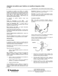
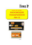
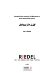
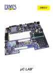
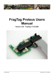
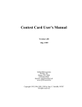
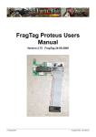
Simpeater
Simplex Repeater Adapter
Installation and Service
Manual
Karter Electronics
10 Manor Avenue
Kidderminster, W orcs
England DY11 6EA
Em ail [email protected]
Tel UK (01562) 82 99 03, International +44 1562 82 99 03
Fax UK (01562) 63 20 24, International +44 1562 63 20 24
Release Record
Manual
Issue
Software
Version
PCB
Version
Description
Date
1
1.0
2
First Production Issue
10/4/96
2
1.0
2
PCB layout modified as per AGC error
1/5/96
3
1.0
2
Application notes modified M110/GM300
20/5/96
4
1.0
2
Parts list Amended
1/6/96
5
1.0
2
GM350 Application Note added
11/9/96
6
1.0
3
CHANGES TO PCB ISSUE 3
11/11/96
7
1.0
3
General Changes to manual address etc
1/4/97
8
1.0
3
Part List amendments/changes
a/98
9
1.0
3
Maxon Application notes added
3/9/98
10
1.0
3
App note 3 amended, part list correction, app note
10 added (Alinco DR130)
1/2/99
11
1.0
3
Specification amended
30/1/03
Karter Electronics
10 Manor Avenue
Kidderminster, W orcs
England DY11 6EA
Em ail [email protected]
Tel UK (01562) 82 99 03, International +44 1562 82 99 03
Fax UK (01562) 63 20 24, International +44 1562 63 20 24
1.
General Description
2.
Specification
3.
Software and Guarantee Statement
4.
Applications
5.
Installation
6.
Radio Specific Installation notes
7.
Operation and Maintenance
8.
Parts List
9.
Circuit Diagrams/Drawings
1. General Description
The Simpeater is a cost effective method of extending radio range using a single frequency. It does this
by recording speech and signalling and then replaying it. This increases range but also doubles the
conversation length.
A typical base station arrangement is shown above. This installation uses the Simpeater connected to the
base station radio. It allows the two portable radios to communicate indirectly using the base station. If
the base station is also to be used then the Simpeater can be simply switched off. Now the base station
will operate in the usual fashion.
Other situations require the Simpeater to be used in a mobile environment. The illustration above shows
how a Simpeater can be used to allow a hand portable user to communicate with base via a mobile radio
over a far greater distance than would otherwise be possible. A typical situation would be when in a poor
coverage area a mobile could be placed in a optimum position, e.g. the top of a convenient hill, then the
users can stay in contact with the base station perhaps working up to several kilometres from the mobile
repeater.
The Simpeater has be manufactured to a high standard using solid state recording technology coupled with
a micro controller. It has been designed for simple installation and maintenance making this product a
leader in its class.
2. Specifications
Electrical
Voice storage
Microprocessor Clock Speed
Supply Voltage
Supply Current
Receive Level
Transmit Level
Carrier Detector
Active State
Level Change
Hold Period
Transmitter lead in delay
Distortion
Frequency Error
Frequency Range
60 seconds
90 seconds
Signal to Noise
Low pass filter
Temperature Range
Record Cycles
Physical
Construction
Dimensions
Front Panel
Connections
TX Level
RX Level
Carrier
AGC
Carrier Hold
Fittings
Non volatile memory cells, Standard 60 Seconds storage
time.
4Mhz
Better than 8 to 18 Volts DC
<10mA Standby
<45mA Recording
<110mA Playback
10mV to 8V Peak to Peak
10mV to 2V Peak to Peak
Positive or Negative
Less than 100mV
Link Selectable - 0.25, 0.5, 1 and 1.5 seconds
150mS
< 2.5%
< 0.5% per message
< 2.5% across full temperature range
+/-3dB
+/- 1.5dB
Better than 300Hz to 3.6 KHz
300Hz to 2.8Khz
Better than 300Hz to 2.3 KHz
300Hz to 1.8KHz
Better than 45dB
Better than 6dB per octave
-10/C to +60/C
Better than 100,000
Two part steel case with internal PCB mounted on pillars
220mm x 178mm x 33mm
Power On Off switch
Power - Green
Carrier - Yellow LED
Transmit - Red LED
14 way screw terminal plug and socket
Level jumper and potentiometer
Level jumper and potentiometer
Phase jumper and threshold potentiometer
Jumper Selectable ON or OFF
Four jumper Selectable settings
4 small adhesive feet are provided for desktop operation
Options
90 second record duration
U bracket for mobile mounting of Simpeater
A range of radio specific connection leads
Please consult your price list for option details
All test measurements have been taken from production samples and reflect a true specification for the
product.
3. SOFTWARE AND GUARANTEE STATEMENT
Each Simpeater comes with a license to operate the software contained in its one time programmable
micro controller. The software ownership is not transferred from Karter Electronics with the purchase of
the equipment. Copying or modifying any part of the operating code is strictly prohibited.
The product is warranted for a period of one year from the date of shipping. This does not cover any costs
incurred returning the product to Karter Electronics.
Karter Electronics will return the product at their expense using their preferred carriers or agents.
If a problem is suspected then the technical support department should be contacted in the first instance.
If it is necessary to return a product for service then a returns number must be sought and all
correspondence should carry this reference number. Returned product for which a returns number has not
been issued may incur costs and a time delay in repair or replacement of the product.
If the product has been modified changed or altered in any way without written agreement then Karter
Electronics reserve the right to refuse maintenance or make a charge appropriate with any extra work that
the alteration has caused. If the product has been damaged by external forces or reasonable care has not
been afforded to the product then a charge may be made in order to return the product to a usable state.
If the product is outside of its warranty period Karter Electronics will advise the cost of any work that may
be required this would usually not include any handling, shipping or local tax (VAT)
charges.
Karter Electronic's liability is limited to the purchase price of the Simpeater. Under no circumstances shall
Karter Electronics, its employees, agents or representatives be liable for any incidental or consequential
damages, nor for any damages in excess of the original purchase price of the Simpeater.
This manual describes the state of this product at the time of its publication, and may not reflect the
product at all times in the future.
4. Applications
The Simpeater can be used in numerous ways, just some of which are detailed below.
Simplex Base Station
This installation is with a mobile radio which is used as a base
station. It would usually be enabled when the operator
was not available or wished to allow users to
communicate with each other through the base station.
This can be especially useful if the radio fleet are
portable radios and the base has a well located
antenna.
Operation is very simple as the Simpeater has been
designed not to impair its host radio's normal operation
when switched off or disabled. Using the front panel switch the unit can
be controlled separately from the radio and when enabled its LED's will indicate the current operational
status. If the disable input is used than the power and Carrier LED's will operate in the usual way but the
Simpeater will remained inert.
Mobile Operation
The concept is to use the Simpeater to pass calls from the mobile to another radio which would usually
be a hand held radio. The typical scenario would be for use in forestry where a user would be alone for
much of the working day and sufficiently far from base that hand portable coverage would not be possible.
The Simpeater is fitted to a vehicle and the vehicle is positioned so as to be in coverage of the base station.
Now the worker is within coverage of the radio system, daily work will be much safer with help just a call
away.
Radio Coverage
A radio survey is often required for new system and confirming existing ones are performing as expected.
This usually takes two people; one sitting in the base station while the
coverage is confirmed by the other driving or walking through the
required coverage area. The Simpeater can remove the need to have
the base station occupied. It also allows the caller to hear each
transmission replayed. This will also identify any unidirectional
path problems which could be over looked in a conventional test.
This test also increases the degradation of the signal as both path
losses are perceived by the tester. Then when the system is
commissioned it will be found to work slightly better than on the
survey.
Community Repeaters
Many countries allow duplex radio repeaters which are shared by a number of different users groups.
Connecting the Simpeater at the hill to site in such a way that it can be selected from a test radio will allow
sales and service staff to demonstrate and test the operation of the system. In such systems it would be
usual to use PL or Selcall code used in order to activate the system this can then be used to enable the
Simpeater by use of its enable input.
If radio coverage tests are carried out on a regular basis then the purchase cost of the Simpeater will be
recovered in a very short time.
How Not to Use a Simpeater
The Simpeater operates by identifying a valid carrier and then
recording the in coming radio signal and then replaying it.
If two Simpeater's are operating on the same frequency
then it would be possible for one unit to receive a
transmission and pass it on to another Simpeater which
would then record the message back to the first unit
which would record that message and so on.
If more than one Simpeater is to be used on a single
frequency then care must be taken to prevent the scenario
detailed above which would eventually end in noise being
transmitted as the voice message slowly degraded with each
transmission.
One solution can be to use different PL tone for each user, assuming that the Simpeater is with a mobile
operator. The base station would then be arranged to scan through a number of channels each set on the
same RF frequency but with a different PL tone. Thus allowing a number of Simpeater's to be used
simultaneously.
5. Installation
The following installation instructions are generic, that is not specific to a particular make or model of
radio. For specific instructions please refer to section 6 which lists all the currently available
application notes.
The Simpeater operates on 8 to 18 Volts DC and
draws less than 200mA, less than 10mA
on standby. Therefore it is best if the
supply is taken from a point after the
mobile radio's on/off switch. Many
radios have an accessory/auxiliary
connector with a low current supply
for this purpose.
To ensure a good ground connection
this should be placed in parallel with
the main feed inside the radio or to a
predefined pin, if the radio has an
accessory / auxiliary connector.
Carrier Indication
As the Simpeater needs to know when the radio is receiving a valid carrier it is imperative that this is
correctly set up. A Valid carrier refers to the RF carrier validated by CTCSS or selective call, if fitted.
As a guide, the only carrier indication sent to the Simpeater should be that which enables the radio's
speaker.
In order to set the carrier activity it is advisable to disable Simpeater operation. To achieve this
connect a wire from pin 4 to +12 Volts.
When carrier pick up point has been identified in the radio, connect this to pin 12 of P1 on the
Simpeater. The phase of the signal is also important, if this output gives a positive voltage when
carrier is present then set JP3,JP4 as shown in the
left hand drawing below, if this output gives a
negative voltage when carrier is present then set
JP3,JP4 as shown in the right hand drawing below.
O
If the carrier LED works in reverse i.e. it is
off when carrier is present and is on with no carrier then simply remove JP3 and JP4 rotate
them through 90/ and then refit them both.
With a valid carrier signal present if the yellow carrier LED on the front of the Simpeater is not
illuminated then adjust R24 (COR Level) until is lights. Now remove the carrier and ensure the yellow
LED extinguishes if it does not then adjust R24 until it does, now apply carrier and repeat. By applying
and removing the carrier a mid point adjustment for R24 should be found. In some cases this may
require careful adjustment if the radio only gives a small DC output between the carrier on and off
states, in most cases it will be a large variation and a mid point setting for R24 is all that is needed.
Receive Audio
If the radio has an auxiliary connector then identify a receive audio path which is not effected by the
radio*s volume control. It is possible that this audio will be before the squelch control and as such may
have noise present when a RF carrier is not present. The level can be from a few millivolts to several
Volts peak to peak. The input circuit has a potentiometer, R5 (RX Level), and a jumper, JP2 which are
used to set the correct level.
Connect an oscilloscope to TP1 and apply an input RF signal to the radio with 60% of maximum
system deviation at a frequency of 1KHz. Now adjust R5 for 2V peak to peak, if AGC is disabled, or
1V Peak to Peak if AGC is enabled. If this adjustment is difficult or the adjustment is at one end of its
travel then either remove or insert JP2 to allow a correct setting.
O
Insert JP2 for an input above 500mVolts P/P.
Response Filter
As receiver audio may not be flat across the audio spectrum then it is necessary check this. Set the
signal generator for a frequency 600Hz and then 1.8Khz and ensure that the deviation is within 3dB of
that for 1Khz. If this is not the case then fit a link in JP6 pin 1 to 2 or 2 to 3. It will be necessary to test
for best response by testing each jumper setting at all three frequencies.
O
When fitting JP6 reset TP1 for the appropriate peak to peak voltage (2V AGC disabled, 1V
AGC enabled) at 1Khz.
Push To Talk (PTT)
The Simpeater uses a relay for this allowing maximum versatility. Three connections are presented to
P1 as shown below.
Most radios use a active low to enable transmit. This is easily achieved by connecting P1, Pin 8 (Relay
Common) to Pin 9 (Ground ) and then connecting the radios PTT to Pin 6 on P1.
Automatic Gain Control (AGC)
The Simpeater will faithfully reproduce the deviation or modulation of an incoming signal. Under
most circumstances this is acceptable but if users are of different audio levels then communication can
be impaired. Many duplex radio base stations offer some AGC and so does the Simpeater. AGC is
designed to even out the variations in the level of the incoming audio. It does this by varying the gain
of an amplifier in response to the level of incoming signal. When AGC is enabled it will increase the
noise floor as the gain of the input amplifier is increased to maximum. If the Simpeater is to be used
exclusively for paging or 5 tone signalling then AGC should be disabled.
O
When AGC is enabled it will cause the
noise floor to increase in level. This
will only be noticeable then silence or
very quiet transmissions are recorded.
This effect will not usually be perceived
users.
Transmit Audio
If the link from Pin 4 to +12 Volts is fitted, then this must be removed to enable the Simpeater to
operate normally.
Identify a point in the radio which flat audio can be presented, this could be in parallel with the
microphone. Connect this point to pin 10 of P1. Apply a modulated carrier to the radio as in the
receive level alignment and leave for 30 seconds. The Simpeater is now recording this audio and
when the carrier is removed the radio will go to transmit. Now set the transmit deviation for 60% of
peak system deviation by adjusting R23(TX Level). If this potentiometer is at one end of its travel then
it may be necessary to install or remove JP1.
If you have connected directly across the microphone then the low impedance of the Simpeater
transmit audio should swamp any audio that may be picked up from the standard radio microphone.
This can be tested by speaking into the microphone, without pressing the PTT button, when the
Simpeater is replaying silence. If speech is heard then the microphone should be modified to prevent
this.
If your microphone is wired as microphone A, above, then if a spare pole is available on the PTT
switch this can be utilized. If this is not available then the circuit can be modified as in microphone 'C'
or 'D'. Microphone 'D' is certain to function as expected where Microphone 'C' may not if the
microphone can find a ground through the radios PTT input circuit.
O
O
Transmit audio must be set after AGC has been selected as the AGC action may effect the level
of output signal from the Simpeater.
The output level is low with JP1 installed.
Enable Input
The Simpeater has an Enable input. By using this input the Simpeater to be enabled or disabled
remotely. The input is used by the Simpeater to validate the start of carrier activity and is only checked
once during each record playback session. As default this pin is low which enables the Simpeater*s
operation.
It is not strictly necessary to connect this pin but it is recommended as any RF pick up could possibly
cause erratic Simpeater operation. If this pin is taken to logic 1 (3 volts or more) then the Simpeater
will still indicate Carrier activity but will remain inert.
The Simpeater should now be fully functional and should be tested for reliable operation. All leads
should be kept as short as possible. The lead from radio to the Simpeater should be screened with the
screen connected at the Simpeater end only. It is advisable to test operation using a hand held radio in
close proximity to the Simpeater just to ensure that RF does not effect the installation.
Simpeater frequency response
Generic Radio Connections
Generic Radio Connections
General Simpeater Test Setup
6. Radio Specific Installation Notes
The following pages show the various application notes available at the time of the last manual update.
If the radio model you are about to install is not covered here then please contact Karter Electronics as
it may now be available.
If during your use of one of our application notes you find an inaccuracy or would like to comment on
any aspect of the note, then please contact Karter Electronics with details. The following notes are
offered in good faith and are believed to be correct, however, as radio's are constantly being improved
it is possible that a note may no longer function as expected so please ensure that the operation of your
Simpeater and radio are fully checked.
Application
Note No
Issue
Radio Manufacturer
Model(s) Covered
1
1
Motorola
M110
2
1
Motorola
M120
3
1
Motorola
GM300
4
2
Motorola
GM900
5
1
Tait
T500
6
1
Tait
T2000 Series
7
1
Motorola
GM350
8
1
Maxon
SM4150
9
1
Maxon
SM2150
10
1
Alinco
DR130
Simpeater, Application Note No 1
Motorola
M110 (MCMicro)
The information below is specific for the Motorola M110. The jumper settings should be correct for
normal operation, however, you may wish to change Carrier Hold Duration and AGC.
When installing the M110 it is necessary to ensure that the
carrier indication is available at the rear connector, Pin 3. If
this is not the case then implement the modification as detailed
opposite - Link Pin 3 to 'KK' and cut JU711.
The M110 does not have power available at its auxiliary connector. This does not present a problem as
power can be provided directly to the Simpeater from the same supply which feeds the radio. This will
result in the Simpeater having to be switched off independently from the radio.
If this operation is unacceptable then the Auxiliary connector could be modified in such a way that
switched 12Volts was available at one of its pins, and that pin then used to supply the Simpeater. If
this is undertaken care should be taken when choosing a pin to prevent damage to other equipment
which could be connected to this point at a future date.
When using the connections as shown the receive audio may not be validated by CTCSS, in this case
as the M110 presents unsquelched audio to the Simpeater the Carrier Hold Time should be set for
minimum by removing JP7 and JP8.
Simpeater, Application Note No 2
Motorola
M120
The information below is specific for the Motorola M120.
The jumper settings should be correct for normal operation, however, you may wish to change Carrier
Hold Duration and AGC.
Simpeater, Application Note No 3
Motorola
GM300
The information below is specific for the Motorola GM300. The jumper settings should be correct for
normal operation, however, you may wish to change Carrier Hold Duration and AGC.
Pin 14 from the GM300 connector is not terminated, this lead reflects the squelch output of the radio.
It is usual to use carrier which is validated by CTCSS. This is present on pin 14, if required this lead
can be removed and radio Pin 8 connected to the Simpeater carrier input Pin 12.
The link from Pin 15 to 16 on the radio is to enable the radio's internal loud speaker.
Pin 9 in the GM300 16 channel ONLY connector can be configured as an alarm input and should
normally be connected to Ground if so configured.
App Note 3, Issue 2 - E&OE
Simpeater, Application Note No 4
Motorola
GM900
The information below is specific for the Motorola GM900.
The jumper settings should be correct for normal operation, however, you may wish to change Carrier
Hold Duration and AGC.
When programming the GM900 it will be necessary to select Data Mode to enable the audio input
from the auxiliary connector. The speaker LED must be illuminated before audio will be passed to the
Simpeater by the GM300, this can be programmed on as default or enabled manually.
App Note 4, Issue 2 - E&OE
Simpeater, Application Note No 5
Tait
T500
The information below is specific for the Tait T500.
The jumper settings should be correct for normal operation, however, you may wish to change Carrier
Hold Duration and AGC.
App Note 5, Issue 1 E&OE
Simpeater, Application Note No 6
Tait
T2000 Series
The information below is specific for the Tait T2000 Series of radio's.
The jumper settings should be correct for normal operation, however, you may wish to change Carrier
Hold Duration and AGC.
The Tait T2000 series of radio's have an optional 15 Pin high density 'D' type connector fitted as an
auxiliary connector. Inside the radio a small PCB is also added to provide 600 Ohm isolated Transmit
and receive audio. If this PCB is not fitted then it is possible to connect the Simpeater by connecting
the points marked S13 and S14 to a 'D' type connector. The Simpeater does not require isolated or
balanced audio so the performance should be equally acceptable with or without the interface PCB.
App Note 6, Issue 1 - E&OE
Simpeater, Application Note No 7
Motorola
GM350
The information below is specific for the Motorola GM350, 128 Channel Version. For the 4 channel
Version see note below. The jumper settings should be correct for normal operation, however, you
may wish to change Carrier Hold Duration and AGC.
Notes:
1.
The above connections are only suitable for the 128 Channel Version of the GM350, to use this
configuration, two of the General Purpose I/o pins must be setup by programming, Pin GP1 (3)
must be programmed to be PTT input, and Pin GP3 (8) must be programmed to be COR
Output.
2.
This above setup is only valid for the 128 Channel unit and as such Karter Electronics do not
recommend connection to the 4 channel GM350.
To use this unit with the 4 channel GM350, the wire from pin 15 (RSSI) can be used as a
carrier detect, you will need to set up the internal COR Level in the Simpeater by trial and
error, NOTE this signal level output is continuously variable depending on signal level.
The Receive Audio Output will have to be taken from Pin 16 (Speaker +), and the Power must
be taken from an alternative source to the internal B+ Output.
Simpeater, Application Note No 8
Maxon
SM4150
The information below is specific for the Maxon SM2150 Radio
Simpeater, Application Note No 9
Maxon
SM2150
The information below is specific for the Maxon SM4150 Radio
NOTES:
1.
2.
A Male plug to fit CON-404 is available from Maxon, PT # 999-084-0
An interconnect PCB which will allow easier connection of wires to the Simpeater is available
from Maxon PT # 610-260-0009
Simpeater, Application Note No 10
Alinco
DR130
The information below is specific for the Alinco DR130 Radio
NOTES:
1.
2.
3.
The radio internal microphone connector can be modified to take RX audio signal, use Pin 8,
disconnect this from ground and connect to hot end of Volume control, the Simpeater RX
audio input is AC coupled so the Simpeater will not affect the Radio operation.
+12V and Ground can be taken directly from the radio supply connector.
To the best of our Knowledge the Squelch output is available on Pin 6 of the microphone
socket, other Alinco Radio’s, or later revisions of the DR130 may have this pin allocated to
other functions.
Application note 10, issue 2 - E&OE
7. OPERATION AND MAINTENANCE
The Simpeater has been designed to be very simple to install and use. It is usual to supply the Simpeater's
power from the radio as it only consumes a small amount of current. The Simpeater*s transmit audio is
applied to the radio via a relay allowing the radio*s microphone to be connected in parallel. In use this
allows a user switch off the Simpeater and use the radio in the usual way.
When the Simpeater first powers up it will ignore any carrier indications for 500ms, this allows the radio
to go through any form power up routine without causing a spurious transmission due to the Simpeater.
In addition if the Simpeater is switched on while the radio that it is attached to is receiving then the
Simpeater will ignore this and will not react to the carrier signal the carrier indication ceases. When the
carrier next becomes active the Simpeater will record and then playback as normal.
After power up the Simpeater has its red power LED illuminated, when an incoming carrier is detected
by the radio it is passed to the Simpeater and the yellow carrier LED will illuminate. The Simpeater is now
recording, when the carrier indication stops the Simpeater will wait a short time, as set by JP7 and JP8,
it will then key the transmitter, wait a short time, and send its recorded audio. If during record mode the
Simpeater runs out of memory i.e. the message length is longer than the maximum message duration, then,
when receive carrier disappears, the Simpeater will send a two short beeps prior to the message replay to
inform the users that the message has been truncated. Once the message has been sent the Simpeater will
return to standby awaiting its next message.
Receive Audio
The Receive Audio input is AC coupled into U5A which is used to amplify or attenuate the signal so
that TP1 is presented with a level of either 1 or 2V peak to peak (dependent on AGC setting) when an
input is set for 60% system deviation at a frequency of 1KHz.
This level at TP1 is set by Jumper J2 which sets the gain of the amplifier U5A and Potentiometer, R5
which attenuates the input signal. Connected to TP1 are two RC networks which are used to select the
frequency response of the stage. This is necessary as the audio presented to this stage could be flat or
pre-emphasized (not de-emphasized) depending upon the radio audio pick up point.
O
In some radios the audio output can be set for pre-emphasized or flat audio by software
programming.
Automatic Gain Control (AGC)
Audio which is presented to Pin 17 of U2, which is the AGC input, it is amplified and then AGC is
applied inside U2. R30 and C25 form the AGC decay time constant while an internal 5K6 resistor and
C25 form the AGC attack time constant.
O
O
The amount of AGC can be effected by changing the audio level at TP1. If this is done care
should be taken as the more AGC that is applied the higher the noise floor will become.
JP5 allows the AGC to be enabled of disabled.
Carrier Detection
The Simpeater carrier detector circuit has been designed to allow the use with a wide range of radios and
as such is very sensitive and will trigger on positive or negative transitions of the carrier input line.
R8, R34, C15, C18 and VR2 form input protection for U5B as well as filtering out any interference which
could be present on this input. R24 is used to set the comparator reference level. These two inputs are
applied to U5B. The inputs can be reversed by removing JP3 and JP4 and reinserting them rotated through
90/. The operational amplifier U5B will act as a compactor allowing LED D4 to indicate when a valid
carrier is present. See installation instructions for more details on setting the carrier activity. D4 will
indicate the true carrier condition, however, this signal is further processed by U4 which adds a carrier
hold timer, with a period of between 0.5 and 1.5 seconds depending upon the setting of JP7 and JP8. This
timer prevents the Simpeater from changing from Receive to Transmit due to a short break in carrier which
could be due to rapid fading for example.
Enable Input
This input to the micro controller, U4, is protected and de-bounced by VR4, R39, D6, C30 and R38. R38
act's as a pull down to Ground to keep the Simpeater in the default enabled state. If this input is taken high
then it will inhibit the operation of the Simpeater.
O
For Normal operation leave the Enable input, P1 pin 4 unconnected or connect to ground, P1 Pin
3.
O
This input prevents the carrier input from triggering a record and playback session. The input is
only tested when an active transition is detected on the carrier input. At this time if the input is
found to be active, greater than 3 volts, than the Simpeater will remain in its standby mode. It is
not necessary to keep this pin low during the complete record and playback process.
Audio storage
While the carrier pin is active audio is continually stored in U2 until the maximum duration of storage is
reached or the carrier indication stops. The Simpeater will now wait for a short period, as set by JP7 and
JP8, if the carrier has not become active during this period then recording stops.
The Simpeater now enters its playback mode, and energizes RL1, which causes the host radio to start
transmitting, then and after a short link establishment period U4 instructs U2 to commence replaying the
stored message. If the recorded message was longer than the capacity of U2 then U4 will insert two short
beeps between energizing RL1 and U2 commencing playback. The beeps indicate to the users that the
message currently playing has been truncated.
Microprocessor
U4 is a single chip micro controller which has been programmed with the software which controls the
operation of the Simpeater. Y2, C12 and C13 are the only external components required for operation of
U4. U4 receives data from a number inputs it also communicates with U2 to control the record and
playback procedures. The truncated message beeps are generated by U4 pin 1, this is then attenuated and
filtered by R29,C21, R28 and C22.
O
O
A full description of the microprocessors activities is beyond this document and it is not required
in order to understand, install and service this product.
If U4 should ever fail then a replacement must be sought from Karter Electronics along with the
Simpeater model and serial number as this contains information specific to your Simpeater.
Transmit Audio
In playback U2 passes the recorded audio to U1A which forms a high pass filter which is required to
remove any CTCSS or DCS signal which might have been present on the audio input.
U1B forms the transmit audio amplifier with output level setting by JP1 and by adjusting R23. The
transmit audio is coupled to the output by RL1 which will then presents a low output impedance
proportional to R15 and the output impedance of U1B. This allows the output to be placed in parallel with
a microphone without effecting the microphone operation when the Simpeater is not in use.
RF Filtering
In order for the Simpeater to operate efficiently it is necessary to prevent RF energy from entering the
circuitry and to prevent the various signals generated inside the Simpeater effecting radio reception. Filter
networks have been placed in series with all the relevant inputs and outputs. This
together with careful consideration to printed circuit layout and a metal enclosure should ensure reliable
operation in all foreseeable applications.
Maintenance and Repair
The Simpeater has only two moving parts, the PTT relay and on off switch, both of which should be
capable of many years trouble free service.
The recording process uses a Non volatile storage method which has a limited life which is greater than
100,000 record/replay operations. In the unlikely event of this number of messages being repeated then
U2 may not accurately reproduce audio. This will be most noticeable at the beginning of each message
as it is played back. This device can easily be replaced following standard anti static proportions.
8. Parts List
Item
Qty
Component Ref
Value
1
2
3
4
5
6
7
8
9
10
11
12
13
14
15
16
17
18
19
20
21
22
23
24
25
26
27
28
29
30
31
32
33
34
35
36
37
38
39
40
41
43
44
45
46
47
48
3
3
2
1
9
2
3
3
2
1
1
1
2
3
1
1
3
1
1
2
1
1
1
1
3
1
1
1
12
4
3
1
8
4
1
1
1
1
1
1
1
1
1
1
1
1
2
C1,C2,C15
C3,C11.C27
C4,C14
C5
C6,C7,C8,C9,C10,C18,C22,C24,C31
C12,C13
C16,C17,C30
C19,C21,C23
C20,C29
C25
C26
C28
D1,D3
D2,D4,D5
D6
F1
FB1,FB2,FB3
JP1
JP2
JP3,JP4
JP5
JP6
JP7
JP8
LK1,LK2,LK3
P1
SW1
Q1
R1,R3,R4,R6,R11,R14,R21,R22,R26-R28,R38
R2,R17,R31,R40
R5,R23,R24
R7
R8,R25,R34,R43,R44,R45,R46,R47
R9,R15,R19,R32
R10
R12
R13
R16
R18
R20
R36
R30
R33
R35
R37
R39
R41,R42
1n
10u
470n
470p
100n
15p
10n
220n
68n
4u7
1uf Tant
220u
1N4002
LED
Zener Diode 4V7
FUSE 500mA
FER BD
Link TX Gain
Link RX Gain
COR Phase
AGC On/Off
De-Emp
COR1
COR2
LINK
14 Way Rt Ang Header
Solder Pads to Power Switch
BC547
10K
1K
47K VAR
10M
100K
470R
4R7
4K7
47K
330R
6K8
47R
39K
470K
220R
22K
3K9
680R
200K
Item
Qty
Component Ref
Value
49
50
51
52
53
54
55
56
57
58
59
60
61
62
63
64
65
66
67
68
69
70
71
72
1
1
2
1
1
1
4
1
3
1
1
1
1
1
1
4
2
4
1
4
1
1
1
1
R29
RL1
U1,U5
U2
U3
U4
VR1,VR2,VR3,VR4,VR5
Y1
Led Spacer
PCB
Case Top
Case Bottom
Front Panel Label
Rear Panel Label
CE Label
M3 X 6 Pan Head Pozi
M3 Locking Washer
M3 x 6/10 CSK Pozi
Switch
Feet
P1 Socket
M3 Nut
Earth link Assembly
Product/Serial No Label
1K2
BT47W/6
LM358
ISD2560 (2590 option)
LM7805
Micro controller
EMC FILTER
4MHz
8mm x 0.1"
KE054400 Issue 3
KE05401
KE05402 issue 2
PVC Back Printed
PVC Back Printed
PVC Back Printed
Nickel Plated Steel Screw
Nickel Plated Steel Washer
Nickel Plated Steel Screw
Single Pole Rocker
12.7mm Sq Rubber Adhesive
14 Way Screw Terminal
Nickel Plated Steel Nut
9. Circuit Diagrams
The following is a list of the drawing numbers associated with the Simpeater Product, these are included
in the installation/service manual as an aid to interfacing and fault finding.
Document No
KE05400
KE05401
KE05404
Description
Printed Circuit Ident
Circuit Diagram
Block diagram