1
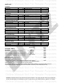
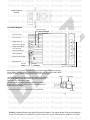
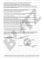
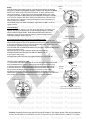
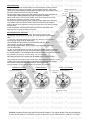
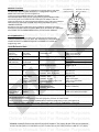
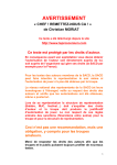
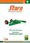
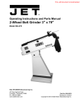
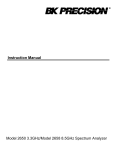
Online Manual Not For Resale Purposes
Online Manual Not For Resale Purposes
Online Manual Not For Resale Purposes
Online Manual Not For Resale Purposes
Online Manual Not For Resale Purposes
Online Manual Not For Resale Purposes
Online Manual Not For Resale Purposes
Online Manual Not For Resale Purposes
Online Manual Not For Resale Purposes
RACING METER
Online Manual NotDCⅡ
For Resale Purposes
Online Manual Not For Resale Purposes
Online Manual Not For Resale Purposes
Online ManualInstruction
Not ForManual
Resale Purposes
Online Manual Not For Resale Purposes
Online Manual Not For Resale Purposes
Online Manual Not For Resale Purposes
Online Manual Not For Resale Purposes
Online Manual Not For Resale Purposes
Online Manual Not For Resale Purposes
Online Manual Not For Resale Purposes
Online Manual Not For Resale Purposes
Online Manual Not For Resale Purposes
Online Manual Not For Resale Purposes
Online Manual Not For Resale Purposes
IMPORTANT - Blitz does not promote the use of this product on public highways. Please obey all local speed
laws. Blitz is not responsible for any accidents or tickets while using this products. Blitz products are listed for
sale and use for offroad vehicles only. Installation of Blitz products may void factory warranty.
WARNING: All images and text in this manual is the property of Blitz Co., Ltd. (Japan). No part of this may be reproduced,
stored in retrevial systems, or transmitted in any form or means with out prior written permission of Blitz Co., Ltd. (Japan).
Online Manual Not For Resale Purposes
Online Manual Not For Resale Purposes
Online Manual Not For Resale Purposes
Online Manual Not For Resale Purposes
Online Manual Not For Resale Purposes
Online Manual Not For Resale Purposes
Online Manual Not For Resale Purposes
Online Manual Not For Resale Purposes
Online Manual Not For Resale Purposes
Online Manual Not For Resale Purposes
Online Manual Not For Resale Purposes
Online Manual Not For Resale Purposes
Online Manual Not For Resale Purposes
Online Manual Not For Resale Purposes
Online Manual Not For Resale Purposes
Online Manual Not For Resale Purposes
Online Manual Not For Resale Purposes
Online Manual Not For Resale Purposes
Online Manual Not For Resale Purposes
Online Manual Not For Resale Purposes
Online Manual Not For Resale Purposes
Online Manual Not For Resale Purposes
Online Manual Not For Resale Purposes
Online Manual Not For Resale Purposes
Notice
Please read and understand this manual before using this product. This manual assumes that you are familiar with
typical automotive systems, basic service and repair operations. You should also have the know how to use
automotive tools and equipment which are necessary to safely and efficiently perform service operations to a
vehicle. Use a factory service manual as a reference. DO NOT attempt to carry out these operations unless you are
competent and these assumptions are correct. Many of the procedures or operations will refer to the factory manual.
Follow all safety precautions described in the factory service manual for the vehicle you are working on to reduce
the possibility of injury to yourself and or others also to avoid the possibility of damage to the vehicle or to render it
unsafe. Read this manual to understand how this product works then install it only after you have full read and
understand this entire manual. Do not attempt to install or use this product with out through knowledge of how the
product works. Please contact Blitz NA or your authorized dealer if there are any questions regarding this product
or of its installation. Blitz NA has the right to update, change, modify, discontinue or supersede the product without
any prior notice.
WARNING
Ignoring these indications may cause serious injuries or even death, also damage to the product or the vehicle may
result causing malfunction. Please read and fully understand this section. Do not operate this product while driving
your vehicle. Make sure after installing the product or any of its parts, it does not interfere with your driving or anything
related to the vehicles day to day use. Please strap or mount any loose parts or wires securely. Blitz NA
will not be responsible for any damages done or caused to the product or the vehicle. The buyer of this product will
take full responsibility for any damages. Do not: drop, misuse, and abuse, alter, take apart or modify this product in
any way, if it has been the warranty will be void. Please confirm you have all parts that came in the original package
without any prior damages, if any parts are missing or damaged please contact your authorized dealer at the place
of purchase. If you notice any strange smells or noises coming from the product, please stop use immediately and
consult your place of purchase/authorized dealer. Due to the fact the vehicle will need to be on and running to verify the
product is working and installed correctly, always perform the installation in a well ventilated area. Bad ventilation may
cause serious injuries, harm or even death. Please do not install any of the parts in any area where it may come
in contact with any type of water/liquid or any type of high heat. This product is designed for 12V DC use only. Do not
attempt to use on 12/24V vehicle or 24V vehicles.
Features of the Racing Meter DC II
Super lightweight compact/low profile design
Weights only 1.34oz and is .8inch thick
Due to size it can be installed virtually anywhere in the vehicle (does not require a lot of depth)
64mm diameter with 60mm area easy to read face
Long life LED illumination with user adjustable brightness (high visibility LED indicators (red, green, yellow)
State of the art microprocessor circuitry
Revolutionary stepping motor technology (1st company to use stepping motor it in a gauge)
Accurate real time monitoring with peak-hold/ warning/recall and record/play back functions
Simple easy to hook-up design (gauges only need to be plugged into LIVE UNIT II/all sensors and harness
plug into the LIVE UNIT II)
Daisy chain simultaneous display function (link all meters for 1 touch operation in record/playback mode)
It is possible to daisy chain up to 6 gauges with the use of 2 live units (3 gauges each)
One live unit can support 3 DC II gauges
Boost sensor built into Live Unit II not additional boost sensor is necessary
The boost gauge can read in real time, delay and peak hold (1 sec)
Dual input temperature meter (Ex. Water/Oil/Trans/Air) Additional sensor is necessary to measure
2 inputs (part #19210)
For the SPEED/POWER gauge user can switch back and forth between speed and power measurements by
pushing 1 button (On certain vehicles it can also cancel the speed limiter).
The EGT/RPM gauge can switch back and forth between exhaust gas temperature and engine rpm
measurements by pushing 1 button
Power and RPM gauge can display in real time and pass/hold
It is possible to utilize high visibility LED indicators (for warning/RPM) with the LIVE UNIT II
(available separately Part #19291)
It is possible to use DC II boost, temp, pressure gauges with LIVE UNIT I (not all functions will work)
WARNING: All images and text in this manual is the property of Blitz Co., Ltd. (Japan). No part of this may be reproduced,
stored in retrevial systems, or transmitted in any form or means with out prior written permission of Blitz Co., Ltd. (Japan).
Online Manual Not For Resale Purposes
Online Manual Not For Resale Purposes
Online Manual Not For Resale Purposes
Online Manual Not For Resale Purposes
Online Manual Not For Resale Purposes
Online Manual Not For Resale Purposes
Online Manual Not For Resale Purposes
Online Manual Not For Resale Purposes
Online Manual Not For Resale Purposes
Online Manual Not For Resale Purposes
Online Manual Not For Resale Purposes
Online Manual Not For Resale Purposes
Online Manual Not For Resale Purposes
Online Manual Not For Resale Purposes
Online Manual Not For Resale Purposes
Online Manual Not For Resale Purposes
Online Manual Not For Resale Purposes
Online Manual Not For Resale Purposes
Online Manual Not For Resale Purposes
Online Manual Not For Resale Purposes
Online Manual Not For Resale Purposes
Online Manual Not For Resale Purposes
Online Manual Not For Resale Purposes
Online Manual Not For Resale Purposes
PARTS LIST
Live Unit II
Live unit
Wire harness
Double sided tape
Short zip tie
1pc.
1pc.
2pc.
1pc.
Wire splices
Instruction manual
Sticker sheet
Long zip tie
2 pc.
1 pc.
1 pc.
1 pc.
Boost Gauge
Boost gauge
Boost sensor
Wire harness
Double sided tape
1 pc.
1 pc.
1 pc.
1 pc.
Short zip tie
Long zip tie
Vacuum hose
Vacuum "T"
1 pc.
1 pc.
1 pc.
1 pc.
Temperature Gauge (oil, water)
Temperature gauge
Temperature sensor
Wire harness
Double sided Tape
1 pc. Short zip tie
1 pc. Long zip tie
1 pc. Instruction manual
1 pc.
1 pc.
1 pc.
1 pc.
Pressure Gauge (oil, fuel)
Pressure gauge
Pressure sensor
Wire harness
Double sided tape
1 pc. Short zip tie
1 pc. Long zip tie
1 pc. Instruction manual
1 pc.
1 pc.
1 pc.
1 pc.
Ex. Temp/RPM Gauge
Ex. Temp/RPM Gauge
Ex. Temp sensor(1/8th PT)
Ex. Temp sensor harness
Tachometer wire
1pc.
1pc.
1pc.
1pc.
1pc.
1pc.
1pc.
1pc.
Speed/Power Gauge
Speed/Power Gauge
Double side tape 50x15mm
Wire Tie Large
1pc. Wire tie small
1pc. wire splice
1pc. ECU diagram
Wire tie large
Wire tie small
Double side tape 50x15mm
ECU diagram
Specification
OPTIONAL PARTS
1pc.
1pc.
1pc.
Part #
19291
19220
19221
19222
19224
19210
19290
19160
754##
Description
M12-1.25
LED indicators 2 pack (for RPM and warning)
for M14-1.25
Temperature fitting ( replaces stock oil drain plug )
M16-1.5
Temperature fitting ( replaces stock oil drain plug )
M20-1.5
Temperature fitting ( replaces stock oil drain plug )
Temp 2 display
Temperature fitting ( replaces stock oil drain plug )
Temperature sensor
Multi Stand ( window gauge mount )
Meter Holder( surface mount pod ring)
Cooling performer ( silicone upper radiator hose with built in temp. adaptor)
1923#
** Cooling performers available for Honda, Acura, Nissan, Toyota, Mitsubishi, Mazda
Oil filter sandwich ( can be used for oil pressure and temp readings )
Hint: Using the cooling performer and oil filter sandwich adaptor makes installation of the water/oil temperature and
oil pressure sensors a lot easier.(Plus if you need to revert back to stock all you do is swap the parts out).
WARNING: All images and text in this manual is the property of Blitz Co., Ltd. (Japan). No part of this may be reproduced,
stored in retrevial systems, or transmitted in any form or means with out prior written permission of Blitz Co., Ltd. (Japan).
Online Manual Not For Resale Purposes
Online Manual Not For Resale Purposes
Online Manual Not For Resale Purposes
Online Manual Not For Resale Purposes
Online Manual Not For Resale Purposes
Online Manual Not For Resale Purposes
Online Manual Not For Resale Purposes
Online Manual Not For Resale Purposes
Online Manual Not For Resale Purposes
Online Manual Not For Resale Purposes
Online Manual Not For Resale Purposes
Online Manual Not For Resale Purposes
Online Manual Not For Resale Purposes
Online Manual Not For Resale Purposes
Online Manual Not For Resale Purposes
Online Manual Not For Resale Purposes
Online Manual Not For Resale Purposes
Online Manual Not For Resale Purposes
Online Manual Not For Resale Purposes
Online Manual Not For Resale Purposes
Online Manual Not For Resale Purposes
Online Manual Not For Resale Purposes
Online Manual Not For Resale Purposes
Online Manual Not For Resale Purposes
Oil filter sandwich
illustration
Live Unit II Diagram
Black tube (TEMP1)
Red tube (TEMP2)
Ignition power plug
EX.T sensor plug
PRESS sensor plug
TEMP1 sensor plug(black)
TEMP2 sensor plug(red)
TACH sensor plug
Warning LED plug(red)
RPM LED plug(blue)
LIVE UNIT
II harness plug
Boost/Vacuum line
Blue plug
Red plug
Gauge plugs
ー
* Connect the RED Wire on the ignition harness to a 12 volt ignition power source and the
BLACK wire to a ground. Verify connections are correct with a digital multimeter or test light.
Use an existing grounding point or choose a soild place free from dirt,grease,oil rust or piant.
Connect the sensors and the gauge plugs as shown in the above diagram.
* Find a suitable location for the Exhaust Temp sensor to be installed.
After mounting EGT sensor fitting make sure probe is inserted into
fitting and is snug with locking coupler.
Once the locking nut is tightened down on the fitting it will NOT
be able to be moved again. Make sure it is in a suitiable area and
doesent need to be moved.
1/8 PT
Locking Nut
* The pressure gauge can be used to read fuel or oil pressure.
Ex.Temp
EGT
b
WARNING: All images and text in this manual is the property of Blitz Co., Ltd. (Japan). No part of this may be reproduced,
stored in retrevial systems, or transmitted in any form or means with out prior written permission of Blitz Co., Ltd. (Japan).
Online Manual Not For Resale Purposes
Online Manual Not For Resale Purposes
Online Manual Not For Resale Purposes
Online Manual Not For Resale Purposes
Online Manual Not For Resale Purposes
Online Manual Not For Resale Purposes
Online Manual Not For Resale Purposes
Online Manual Not For Resale Purposes
Online Manual Not For Resale Purposes
Online Manual Not For Resale Purposes
Online Manual Not For Resale Purposes
Online Manual Not For Resale Purposes
Online Manual Not For Resale Purposes
Online Manual Not For Resale Purposes
Online Manual Not For Resale Purposes
Online Manual Not For Resale Purposes
Online Manual Not For Resale Purposes
Online Manual Not For Resale Purposes
Online Manual Not For Resale Purposes
Online Manual Not For Resale Purposes
Online Manual Not For Resale Purposes
Online Manual Not For Resale Purposes
Online Manual Not For Resale Purposes
Online Manual Not For Resale Purposes
* The temperature gauge can read either oil or water temperature. An additional sensor MUST be
added for another reading. Please note that for Temp 1 reads, the temp sensor must be
hooked up to the Temp 1 plug with the BLACK wire cover. Temp 2 requires an ADDITIONAL
sensor ( part # 19210 ) hooked up to the RED wire cover temperature sensor plug in order to work.
On the Temp gauge when the green Led is on it is reading Temp 2, when the green LED is OFF it is reading Temp 1
Hint: You can use a oil drain adaptor plug(sold seperately). So that you can install the oil temp sensor where the stock
oil drain would go(no drilling and easy to install)
* RPM/Tach interface. Please connect this white wire to the tachometer signal coming from the engine to the ECU.
Do not tap directly off the engine or any other location other than on the ECU harness.
If the external RPM LED indicator is installed then it will illuminate also.
Please refer to service manual to locate color and description.
* The red plug is for an option external warning indicator and the blue plug is for the RPM/Tach shift indicator.
Optional LED Warning Indicator part# 19291 is needed(avalible seperately).
* The 5pin LIVE UNIT II harness plug :
If the car has a speed cut then use both wires if the car doesent then only use the orange wire.
Orange is connected to the speed sensor(engine side) side of the speed sensor wire for the Speed/Power gauge
Brown is connected to the ECU side of the harness.
If the car does not have a speed cut and/or causes a check engine light when the speed sensor wire is cut then you will
only use tap the orange wire(w/o cutting) and not use the brown wire.
The orange and brown wires are not needed if the Speed/Power gauge is not used.
Yellow & Green is for 1 touch peak hold capability when using 2 live units.(If only one live unit is bieng
used then these wires are not applicable, If you are using 2 live units then you need to plug them into each other)
White is connected to 12V+ constant to reset gauges to 0 when you remove the key.
(If the white wire is not connected the gauge will stay in whatever position it was left in.)
* The vacuum/boost pressure must be drawn from a source behind the throttle body to insure accurate
readings. (you can use the line off the fuel pressure regulator)
*** Cooling Performers can be purchased for water temp. readings
*** Oil sandwich adaptors can be purchased for oil temp. and pressure readings
*** Oil drain adaptors can be purchased for oil temp. readings
Do not modify or shorten sensor harnesses. This list consists of the minimum reqiured parts. Depending on the vehicle
and method of installation, there maybe additional parts that are needed. Please contact your authorized dealer for any
additional parts you may need. Make sure all sensors, wiring, and connections are secure and safe before
starting or driving the car.
OPERATING INSTRUCTIONS
WARNING: All images and text in this manual is the property of Blitz Co., Ltd. (Japan). No part of this may be reproduced,
stored in retrevial systems, or transmitted in any form or means with out prior written permission of Blitz Co., Ltd. (Japan).
Online Manual Not For Resale Purposes
Online Manual Not For Resale Purposes
Online Manual Not For Resale Purposes
Online Manual Not For Resale Purposes
Online Manual Not For Resale Purposes
Online Manual Not For Resale Purposes
Online Manual Not For Resale Purposes
Online Manual Not For Resale Purposes
Online Manual Not For Resale Purposes
Online Manual Not For Resale Purposes
Online Manual Not For Resale Purposes
Online Manual Not For Resale Purposes
Online Manual Not For Resale Purposes
Online Manual Not For Resale Purposes
Online Manual Not For Resale Purposes
Online Manual Not For Resale Purposes
Online Manual Not For Resale Purposes
Online Manual Not For Resale Purposes
Online Manual Not For Resale Purposes
Online Manual Not For Resale Purposes
Online Manual Not For Resale Purposes
Online Manual Not For Resale Purposes
Online Manual Not For Resale Purposes
Online Manual Not For Resale Purposes
Gauge Functions
Press the MODE button to switch between readings. If the Green L.E.D. flashes once the gauge will
read in real time . If the Green L.E.D. flashes twice the gauge will read in delay mode.
If the Green L.E.D. flashes three times, the gauge will read in pass and hold mode.(Boost and Pressure readings only)
Power and RPM can read in realtime or passing/hold mode only. Temp,Speed and EGT can read in real time only.
Everytime the "MODE" switch is pushed it cycles from realtime to delay to passing hold. If MODE switch is held down it
goes into warning setting mode.
On the TEMP gauge the Mode switch toggles from Temp 1 to Temp 2
(For TEMP 1 the green LED is off and in TEMP 2 the green L.E.D. is on)
For the Speed/Power gauge each push of the MODE switch toggles from real time speed to real time power to
pass and hold power.
(In Speed mode the green L.E.D. is out and in Power mode the green L.E.D is on)
On the EX Temp/REV meter the Mode switch toggles from real time EGT to real time RPM to pass and hold RPM
(In EGT mode the LED is off and in REV mode the green L.E.D. is on)
PEAK sw.
Peak
Push the PEAK button once to show the highest reading achieved. The Yellow L.E.D. will
appear. Press the PEAK button again to get out of peak mode. To reset the peak, hold the
PEAK button down for 2 seconds when in peak display. The gauge will retain memory of
the last highest peak setting until it is reset on the gauge. When 2 sensors are used on the
TEMP sensor it can only show the peak value of the highest one(either 1 or 2) not both.
YellowLED
Peak display
Warning
When the preset warning value is achieved the red led on the gauge will illuminate. If
optional LED warning indicator is installed it will also light. To set warning press MODE
button for 2 seconds. The Red L.E.D. will turn on. Press the PEAK button to move
increase warning and press the REC. button to decrease warning. Press the MODE
button to set. The Red L.E.D. should turn off.
For PRESSURE METER there is a low and high pressure warning. First set low
warning level and then press MODE button to set the high warning level. Press MODE
button again to set. If set improperly the Red L.E.D. will stay on. If optional external
warning LED is installed it will also illuminate.** The LOW pressure warning MUST
be set before HIGH pressure warning. On the TEMP gauge the warning value
applies to both sensors at the same time it cannot distinguish between temp 1 or
temp 2. (It is not possible to set each warning seperately)
Record
Press and hold Record button for 2 seconds in order to for the gauges to record. The
red L.E.D. will flash continuously while recording. Press the Record button again to
stop recording. All L.E.D. should be off when not recording. The Record feature can
record up to 99 seconds. After aproximately 89 seconds the red L.E.D blinks quickly
to inform it is nearing the end. You may also turn off the recording by pushing the
REC switch. Until new information is recorded over, it will hold memory of the last
recorded information. If the power source is interupted (ignition is turned off) while
recording the data recored will be deleted.
MODE sw. ( 1 sec)
PEAK sw.(UP)
REC sw.
(DOWN)
RedLED
Set Warning
REC sw.
(1sec)
LED blinking
Record function
WARNING: All images and text in this manual is the property of Blitz Co., Ltd. (Japan). No part of this may be reproduced,
stored in retrevial systems, or transmitted in any form or means with out prior written permission of Blitz Co., Ltd. (Japan).
Online Manual Not For Resale Purposes
Online Manual Not For Resale Purposes
Online Manual Not For Resale Purposes
Online Manual Not For Resale Purposes
Online Manual Not For Resale Purposes
Online Manual Not For Resale Purposes
Online Manual Not For Resale Purposes
Online Manual Not For Resale Purposes
Online Manual Not For Resale Purposes
Online Manual Not For Resale Purposes
Online Manual Not For Resale Purposes
Online Manual Not For Resale Purposes
Online Manual Not For Resale Purposes
Online Manual Not For Resale Purposes
Online Manual Not For Resale Purposes
Online Manual Not For Resale Purposes
Online Manual Not For Resale Purposes
Online Manual Not For Resale Purposes
Online Manual Not For Resale Purposes
Online Manual Not For Resale Purposes
Online Manual Not For Resale Purposes
Online Manual Not For Resale Purposes
Online Manual Not For Resale Purposes
Online Manual Not For Resale Purposes
Replay
Press and hold the REC. button down for 4 seconds and the gauges will all replay.
(the green L.E.D will be blinking)While in Replay mode the user can press the MODE
button once to show replay in twice real time speeds. In replay mode the Green
L.E.D. will be flashing. To stop replay mode press the PEAK button once or wait
for replay to end. When multiple meters are connected(daisy-chained) it is possible
to do one touch operation. Also when making them replay/record at the same time.
User will still need to operate the warning/peak display functions seperately since
these functions are not linked.
On the TEMP gauge if the TEMP 2 reaqding is higher than the TEMP 1 it will not
operate correctly.
REC sw.
(3sec)
LED blinking
Replay function
Contrast display
Hold the MODE button down for 4 seconds, till the Red, Green, and Yellow L.E.D.
appears. Then press the PEAK button to make the display brighter or the REC.
button to make the display darker. Press the Mode button till the Red L.E.D.
disappears. Gauge will be at maximum reading to indicate full brightness and
at its lowest setting for minimun dimness.
Speed setting
Programming/Calibration Instructions for Speed/Power meter
Speed and power readings will not be accurate if the vehicle's speed signal value
and the speed inspection value on the Speed/Power meter do not match. Test drive vehicle
to see if the Speed/Power meter and vehicles speedometer match. If it does not it may
be necessary to calibrate the gauge to the vehicle.
Press and hold down the PEAK button while turning the ignition on. Release after guage
goes through self test mode.
(the green and red L.E.D. lights will blink. Needle will point to 40km/h)
Pushing the PEAK switch will toggle from 40km/h to 80km/h to 2P to
to 4P to 8P and 16P (pulses)
Pushing the REC switch will cause it to toggle backwards from 16P to 40km/h
Push down PEAK with IGN
on
LED blinking
There is 3 ways to calibrate the meter:
1. If you know the output pulses from the car you can choose from 2P,4P,8P and 16P.
Push the MODE switch to select the setting(gauge will self test then point to zero)
2. Drive the vehicle at a constant 40km/h(25mph) then push MODE button to set.
Push REC
3. Drive the vehicle at a constant 80km/h(50mph) then push MODE button to set.
for down
We recommend the 80km/h(50mph) calibration for the most accurate results.
Sometimes under varying loads there may be a different reading from the factory
speedometer compared to the Speed/Power Meter this is normal and not a malfunction.
If the variation is a considerable difference then you may need to recalibrate.
Press PEAK
for up
Push MODE to set.
When MODE switch is pushed, Vehicle speed
pulse function ends and Speed calibration starts
Speed calibration
WARNING: All images and text in this manual is the property of Blitz Co., Ltd. (Japan). No part of this may be reproduced,
stored in retrevial systems, or transmitted in any form or means with out prior written permission of Blitz Co., Ltd. (Japan).
Online Manual Not For Resale Purposes
Online Manual Not For Resale Purposes
Online Manual Not For Resale Purposes
Online Manual Not For Resale Purposes
Online Manual Not For Resale Purposes
Online Manual Not For Resale Purposes
Online Manual Not For Resale Purposes
Online Manual Not For Resale Purposes
Online Manual Not For Resale Purposes
Online Manual Not For Resale Purposes
Online Manual Not For Resale Purposes
Online Manual Not For Resale Purposes
Online Manual Not For Resale Purposes
Online Manual Not For Resale Purposes
Online Manual Not For Resale Purposes
Online Manual Not For Resale Purposes
Online Manual Not For Resale Purposes
Online Manual Not For Resale Purposes
Online Manual Not For Resale Purposes
Online Manual Not For Resale Purposes
Online Manual Not For Resale Purposes
Online Manual Not For Resale Purposes
Online Manual Not For Resale Purposes
Online Manual Not For Resale Purposes
Weight Calibration
It is necessary to input the vehicles weight for acurate horsepower readings. Hold the
MODE switch when turing on the ignition to go into weight input mode. The red and
yellow L.E.D.s will be blinking the needle will point to input weight. (For instance: If it is
pointing at 150km/h that means its weight is 1500kg)
Use the PEAK switch to raise and the REC switch to decrease weight. Example if the
vehicles weight is 2000kg(4400lbs) The needle should point at 200km/h.
Make sure the input is as accurate as possible. If the correct weight is not inputted
the gauge will not measure correctly!!! Hint:1kg=2.2lbs
For the most acurate input please weight vehicle at a public weight station with driver
in car. Make a note of the amount of fuel in vehicle as a full tank of gas weight is
drasticly different than compared to a empty tank of gas. Which may alter the readings
from the meter.
In order to eliminate misreadings from wheel spin there is a slight delay at the
beginning when the gauge is reading horsepower.
Hold down MODE with
IGN on
PEAK switch (UP)
REC switch
(DOWN)
LED blinking
Driveline/Power Loss Correction
To program driveline hold down Rec switch when turning on ignition. After
self test green and yellow L.E.D.s will blink. The needle will point to either 2WD or
4WD.
** In the case of the Nissan Skyline GT-R and/or any other type of car that has a
torque split type driveline use the 2WD setting.
Using the PEAK and REC buttons you can switch back and forth. Set to
correct driveline by pushing the MODE switch.
After pushing the MODE switch driveline selection ends and it becomes Power/
Loss correction setting.
You can use the PEAK switch to increase the values and the REC switch to decrease it.
100km/h is the equivalent of 0. Each push of the PEAK button increases the correction
by 1 making 400km/h = +30. Pushing the REC button decreases the power loss correction.
It is posssible to go as far as -10 on the gauge. -10 =0 on the gauge.
After setting the power loss correction push the MODE switch to end programing.
Push MODE to end
weight input
These references are for factory stock vehicles. If the vehicle has been modified in anyway
including, aero components and power improvements it will cause incorrect readings.
Also if vehicle has larger/smaller diameter wheels, this will also cause
incorrect readings. You can use the Power Loss correction to correct this.
Resistance Correction
Push REC with IGN on
LED blinking
Power Loss correction
Driveline selection
Selects with PEAK and REC
switch
Push MODE switch
REC switch
(DOWN)
PEAK switch (UP)
All LED blinking
Push MODE switch to
end
WARNING: All images and text in this manual is the property of Blitz Co., Ltd. (Japan). No part of this may be reproduced,
stored in retrevial systems, or transmitted in any form or means with out prior written permission of Blitz Co., Ltd. (Japan).
Online Manual Not For Resale Purposes
Online Manual Not For Resale Purposes
Online Manual Not For Resale Purposes
Online Manual Not For Resale Purposes
Online Manual Not For Resale Purposes
Online Manual Not For Resale Purposes
Online Manual Not For Resale Purposes
Online Manual Not For Resale Purposes
Online Manual Not For Resale Purposes
Online Manual Not For Resale Purposes
Online Manual Not For Resale Purposes
Online Manual Not For Resale Purposes
Online Manual Not For Resale Purposes
Online Manual Not For Resale Purposes
Online Manual Not For Resale Purposes
Online Manual Not For Resale Purposes
Online Manual Not For Resale Purposes
Online Manual Not For Resale Purposes
Online Manual Not For Resale Purposes
Online Manual Not For Resale Purposes
Online Manual Not For Resale Purposes
Online Manual Not For Resale Purposes
Online Manual Not For Resale Purposes
Online Manual Not For Resale Purposes
Power/Loss correction List
Vehicle Type
Passenger vehicles Examples
under 1000cc
1000cc - 1600cc
All Corolla/Civic/CR-X/87-89 Integra/
Naturally Aspirated Mirage/Mx-5-Roadster/
1601cc to 3000cc
NSX/S2000/GTO/RX-7/MR-2/MA-70
Naturally Aspirated/ Celica/Aristo/MR-S/IS300-200/Eclipse
All Turbo/
Skyline/S13-S14/Imprezza/Z32/Lancer/
Supercharged
Sedans
Settings
2WD
1
4WD
1
-2
-2
0
0
0
0
2
2
Stationwagon
Xb/Xa/Alero
2
2
Mininvans
Rav 4/MPV/CR-V/Element
3
3
SUV
Grand Vitara
5
5
RV
Landcrusier/4Runner/Montero
8
8
Other
*JZA80 Supra TT 93~
-5
-5
**For vehicles that have speedcut limiters.
Speed Limit setting
Initial value is set at 170km/h(107mph)
If the brown wire on the LIVE UNIT II harness is not used or the vehicle does NOT
speed cut, this function is NOT necessary. Please do not test on public highways
this function is designed for off-road use vehicles such as track/race vehicles on
closed curcuits and race/speed ways.
Push the PEAK and MODE buttons while turning on the ignition. Green and yellow
L.E.D.s should be blinking alternately. Needle should point to speed limit reading.
Using the PEAK and Rec switches more the needle up and down to the desired
setting for the speed cut. Setting the needle to 0 (farthest location counter-clock wise)
will disable the speed limiter. Push MODe switch to set and return to real time
monitoring.
Note: There are times on certain cars where the speed cut function may not work.
Warning: Do not verify or test the speed cut function on a public road. Please consult
a BLITZ authorized dealer for any assistance you may need.
Speed
Pushing PEAK and MODE switch with
IGN on
LED alternate blinking
REC switch PEAK switch (UP)
(DOWN)
WARNING: All images and text in this manual is the property of Blitz Co., Ltd. (Japan). No part of this may be reproduced,
stored in retrevial systems, or transmitted in any form or means with out prior written permission of Blitz Co., Ltd. (Japan).
Online Manual Not For Resale Purposes
Online Manual Not For Resale Purposes
Online Manual Not For Resale Purposes
Online Manual Not For Resale Purposes
Online Manual Not For Resale Purposes
Online Manual Not For Resale Purposes
Online Manual Not For Resale Purposes
Online Manual Not For Resale Purposes
Online Manual Not For Resale Purposes
Online Manual Not For Resale Purposes
Online Manual Not For Resale Purposes
Online Manual Not For Resale Purposes
Online Manual Not For Resale Purposes
Online Manual Not For Resale Purposes
Online Manual Not For Resale Purposes
Online Manual Not For Resale Purposes
Online Manual Not For Resale Purposes
Online Manual Not For Resale Purposes
Online Manual Not For Resale Purposes
Online Manual Not For Resale Purposes
Online Manual Not For Resale Purposes
Online Manual Not For Resale Purposes
Online Manual Not For Resale Purposes
Online Manual Not For Resale Purposes
REV Meter Calibration
Push MODE to set
The gauge is preprogramed for 4cyl applications. To change to 6cyl. push down
calibration and end.
the REC switch when the ignition is turned on. To change back to 4cyl hold
MODE switch down when you turn the ignition on.
To ensure accurate readings make sure you calibrate the gauge.
Push the PEAK switch when you turn on the ignition to go into calibration mode.
The red and green L.E.D.s blinks and the needle points to 3000rpm. After the
engine has warmed up to normal operating temperature rev the engine up to 3000rpm.
When the factory tachometer and RPM meter match push MODE to set and
calibration mode ends.
Sometimes under varying loads there may be a different reading from the factory
tachometer compared to the Ex Temp/REV Meter this is normal and not a malfunction.
If the variation is a considerable difference then you may need to recalibrate.
Ex.Temp/REV Warning
After ignition is turned on and meters have gone through the self-test mode
Hold down MODE button for 1 sec. Red L.E.D. should light up. Use PEAK for up
and REC for down to set RPM warning level. Push MODE 2x to set and exit
programming mode.
Push PEAK when turning
IGN on to calibrate
LED blinking
Engine RPM calibration
Quick Reference Chart
MODES
Reading displays
(boost and
pressure only )
Speed and Ex.
Temp Meter only
Power and
RPM meter only
Peak hold
OPTIONS
Real time
Delay mode
Pass and hold
Real time
Warning
Display
Set
Replay
To record
To Stop record
To Replay
To Replay twice speed
To Stop replay
Gauge contrast
Contrast
BUTTONS TO PRESS
Real time
Pass and hold
Display
Reset
Temperature toggle 2 temp sensors are
( only on temp
required
gauge)
Press MODE once
Press MODE once
Press MODE once
Press PEAK once
Hold PEAK down for 2 sec.
Press MODE for 1 sec.
Press PEAK Button to increase
Press REC. button to decrease
Press REC. for 2 sec.
Press REC. button
Press REC. for 4 sec.
Press MODE. while in replay mode
Press PEAK button
Press MODE button for 4 sec.
Press PEAK increase
Press REC. to decrease
Press MODE button
LED STATUS(on gauges)
Green L.E.D. Flash 1x
Green L.E.D. Flash 2x
Green L.E.D. Flash 3x
Green L.E.D. Flash 1x
Green L.E.D. Flash 2x then stays on
Green L.E.D. Flash 3x then stays on
Yellow L.E.D. on
Yellow L.E.D. off
Red L.E.D. on
Red L.E.D. on
Red L.E.D. on
Red L.E.D. Flash
Red L.E.D. off
Green L.E.D. Flash
Green L.E.D. Flash faster
All L.E.D.s off
All L.E.D.s will be on
Green L.E.D. will be off for temp 1
Green L.E.D. will be on for temp 2
Note: Regarding the Boost meter.
There are times when the needle/pointer on the boost gauge may not return to 0 after self test.
To "Zero" in the gauge hold down PEAK and REC switch on the boost gauge when you turn on the ignition. All
L.E.D.s will light up. Use the PEAK button to raise and the REC button to lower the needle/pointer to the proper
location. Push the MODE switch to return to exit programming and return the gauge to real-time monitoring.
WARNING: All images and text in this manual is the property of Blitz Co., Ltd. (Japan). No part of this may be reproduced,
stored in retrevial systems, or transmitted in any form or means with out prior written permission of Blitz Co., Ltd. (Japan).