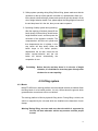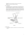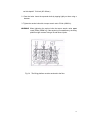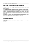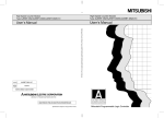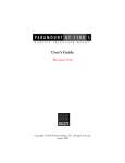
1
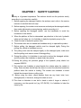
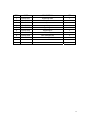
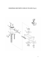
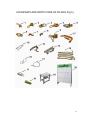
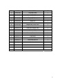
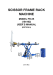
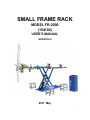
SMALL FRAME RACK
MODEL FR-2000
(154102)
USER’S MANUAL
(VERSION A)
2011. May
1
Content
Preface
Chapter 1:Safety caution
Chapter 2:Introduction of the machine (specification and usage)
Chapter 3:Delivery and receiving
Chapter 4:Lifting system
4.1
Safety
4.1.1
4.1.2
4.1.3
4.2
Lifting frame structure
4.2.1
4.2.2
4.2.3
4.3
Bench
Lifting device
Hydraulic system
Installation and test
4.3.1
4.3.2
4.3.3
4.3.4
4.4
General introduction
Warning and important notes
Safety device
General introduction
Location requirements
Installation of lifting bench
Fix to the ground and test
Operation
4.4.1
4.4.2
4.4.3
General introduction
Vehicles lifting operation and warnings
Vehicles loading operation and warnings
4.5
Maintenance
4.6
Disassembly and repairing
4.6.1
4.6.2
4.6.3
General introduction
Mechanical parts
More
2
Chapter 5: Tower system
5.1
Safety
5.1.1
5.1.2
5.2
General introduction
Warnings
Drawing arm
5.2.1
5.2.2
5.3
Structure
Specification
Installation and test
5.3.1
5.3.2
5.3.3
5.4
Matching
How to fix on to platform
How to disassemble from platform
Operation
5.4.1
5.4.3
5.5
Preparation before pulling
Some examples
Maintenance
5.5.1
5.5.2
5.5.3
5.5.4
Chapter 6:
General introduction
Hydraulic system
Mechanical parts
Disassembly of accessories
Clamping
6.1
General introduction
6.2
Basement of clamp
6.3
Jaw
6.4
Work principle
Chapter 7:
Trouble shooting
Ending
3
PREFACE
As the increasing development in auto technology and extensive using of
new materials, the repairing technique has to meet the needs of auto industry’s
development. The traditional auto’s body is made from soft steel or medium steel
but the modern auto body is made from hard steel, which leads to great
differences in repairing.
After collision, we have to apply full range cold pulling to straighten and avoid
heating repairing in case of any change in metal’s inner structure which will
reduce the intensity.
Model FR-2000 applies hydraulic power and provides many plate metal
accessories which can help us to recover the collided places to the original state.
In order to guarantee the precision of straightening, A set of high-precision
measuring system is needed.
This manual includes installation, using as well as maintenance. It has very
specific introduction on machine’s structure principle, basic using and flexible
using of accessories.
During installation, using and operation, please obey the safety requirements
of this manual strictly in order to avoid any emergency and injury. We have very
detailed prescripts over the max load and max pressure, please obey it strictly in
case of any danger and damage to property and injury to people.
Model FR-2000 has full consideration over the practical repairing, and it has
safety design on structure, dimension and choice in materials. Based on
pragmatism and humanism, our bench is designed and collocated in order to help
the repairing workers more.
4
CHAPTER 1
SAFETY CAUTION
Safety is of greatest importance. The workers should use the products strictly
according to our instruction carefully.
1. Before repairing the damaged vehicle, the workers must, refer to the service
manual, do as what the book says.
2. Before repairing, the workers must measure and analyze the damaged vehicle,
then make adjustment process planning, and do according to it.
3. Before repairing the damaged vehicle, use the handbrake to avoid the
movement of the vehicle.
4. When the platform is lifted or descended, pay attention to the tools, hydraulic
tubes and air tubes, etc. it is forbidden to bake the hydraulic pump by fire.
5. Check the seal of hydraulic system often.
6. The workers who are not trained are forbidden strictly to operate the product.
7. Before pulling, the damaged vehicle must be clamped tightly. During the
pulling, the vehicle is forbidden to move.
8. The pulling tools must be clamped tightly on the damaged parts, make sure
that the pulling tools cannot come off during pulling.
9. During the pulling, it is forbidden to use jack to anchor the damaged vehicle,
and the workers are forbidden to stand under the vehicle.
10. During the pulling, the pressure gauge of the hydraulic pump should not
surpass 6000PSI.
11. The workers are forbidden to stand beside the vehicle when the vehicle is
lifting. Some workers should help the driver to control the direction beside the
platform when the vehicle is loading. The workers are forbidden to stand
behind the stressed chain or pulling tools.
12. Before using the chain, check whether there are any bend, twist, knot,
damaged parts, if there are, change the chain at once.
13. The chain is forbidden to use bolt or bend to make it longer or shorter, if
necessary, use the special tool (e.g. DC-G4120). It is forbidden to bake the
chain by fire.
5
CHAPTER 2
INTRODUCTION
Model FR-2000 is a frame style collision repair system. It features low starting
point, high lifting height, smooth lifting and lowering, strong hydraulic power,
universal and standard fixing system as well as various tools. There is no dead
point in the pulling tower’s working scope which makes sure straightening in
multi-point and all-wave. Our measuring system can be used to measure both the
chassis and auto body. Comparing with the vehicle’s data sheet to judge if it
accords with the original data, thus we can make sure of the precision of repairing
in this scientific way.
Model FR-2000 SPECIFICATIONS
Bench length---------------123-5/8” (3140mm)
Bench width ----------------37” (940mm)
Bench height---------------4-3/4”—63” (120-1600mm)
Hydraulic pressure--------6000PSI (Max)
Post Max. Tension -----------100KN
Post Working Rang ----------360°
Pneumatic Pressure ---------0.5-0.8Mpa
Total weight------------------3500lbs (1600Kg)
Max load----------------------5500lbs (2500Kg)
Noises-------------------------≤75dB
6
CHAPTER 3
TRANSPORTATION AND RECEIVING
1、Transportation
The transporting truck must be longer and wider than the bench itself. During transporting, the
machine should be fixed in order to avoid bumping. Every single part of the machine and the
painting will not be damaged. Moreover the machine must be protected from rain.
2、Hoisting and installation
Use hoisting machine with 11000lbs (5 ton) capacity to hoist the bench. Use four steel ropes
symmetrically on the four positions of the bench to avoid tilt. If using a forklift, the fork length
must be 1 meter long and the lifting capacity should be more than 4400lbs (2ton). The two
arms should be used to lift the bench transversely. The weight on the two side of the arm shall
be even in order to avoid tilt.
3、Receiving introduction
Please check the goods if the machine and accessories are in accordance with what you
ordered and there is no damage in transportation. If there is any unconformity in quantity or
damage, please contact with your distributor immediately.
7
CHAPTER 4
PLATFORM MANUAL
4.1 Safety
4.1.1 General
Information given in this manual describes the suggested best working practices and
should in no way take precedence over individual responsibilities or local regulations.
Great effort has been placed on the design and manufacture of the model 154120 lifting
platform so that it will comply with all applicable safety aspects for this type of equipment.
During operation and other work, it is always each individual’s responsibility to consider
the following things:
z
z
Their own and others’ personal safety.
Make sure of the safety of the lifting platform through correct use of the equipment in
accordance with the descriptions and instructions given in this manual.
By observing and following the safety precautions, the user of the TECHER 2 lifting
platform will ensure safe working conditions for himself / herself and his/her fellow
workers.
To avoid personal injury, the following regulations must be observed:
z Maximum vehicle weight = 5,500lbs (2,500Kg.)
z Check to make sure that the lift is fixed securely to the floor in accordance with the
installation instruction, refer to Chapter 3.6.
z Check to make sure that there are no objects obstructing the movement of the lift.
z Check to make sure that the vehicle is positioned correctly on the lift and that it cannot
move during a lift.
z Always keep a careful watch on the lift and its load when raising and lowering. Keep
lift area clear.
z Ensure that nobody is close to the lift when it is operating.
z Read the manual carefully for information regarding installation, operation,
maintenance and trouble shooting.
Various warnings and notices are placed beside illustrations and important descriptive
texts in this manual. These warnings and notices are important to ensure the safety of the
user and others.
Safety signs must also be in place on the equipment. These are intended to warn of
hazardous situations or to draw attention to incorrect uses of the equipment.
8
4.1.2 Warnings and important notices
Prohibited!
Prohibit behavior that may cause injury.
Warning! Warnings of personal injuries or of damages in equipment.
The following warnings and important notices are used in the instruction manual:
WARNING! (In bold, italic type) is used in this manual to indicate a possible danger that
could lead to personal injury. An instruction is normally given, followed by a short
explanation plus the possible effect if the instruction is not followed.
IMPORTANT! (In bold, italic type) is used in this manual to indicate practical information.
It is also used to indicate a possible danger that could damage to the equipment and/or
cause environmental damage.
NOTE! (In bold, italic type) is used to emphasize supplementary information that is
required for problem-free use of optimal use of the lifting platform.
In addition to the safety signs illustrated above, the following warnings and important
notices appear in the manual:
WARNING!
Make sure that the four main clamps grip the vehicle firmly
during lifting. Otherwise the vehicle might overturn and
injure people around.
WARNING!
Maximum allowed vehicle weight is 5,500lbs (2,500 kg). Be
careful and try to prevent platform tilting, which may cause
injuries.
!
!
!
!
!
WARNING! The lifting platform is heavy. Use only approved lifting
equipment to avoid accidents. Risk of injuries.
WARNING!
Danger of tripping on loose hoses. Risk for injuries.
WARNING!
Before lowering the platform, make sure that the immediate
area is cleared. Risk for crush injuries.
9
WARNING!
The FR-2000 lifting platform is designed to be permanently
anchored to the floor. If the lift is used without being
properly anchored to the floor according to these
instructions, there is an imminent risk that it will tilt and
causes injuries.
WARNING!
If there is any uncertainty regarding the quality of the floor,
please get an expert to inspect the floor before the lifting
platform is anchored to the floor. Risk of platform tilting may
cause injuries.
WARNING!
When tightening the anchor bolts, the torque wrench value
[53 Nm (469lbf.in)] must be reached. If the anchoring is
unsatisfactory, the lifting platform might overturn during a lift
and cause injuries.
WARNING!
!
Always be extremely careful when working with jacks or
hydraulic equipments. Risk of falling or of flying objects.
!
WARNING! It is not allowed to place more than one extension block
(Extension 60) on each lifting pad. Risk of vehicle tilting.
!
!
!
!
!
WARNING! When placing the vehicle on the lifting platform, make sure
that the vehicle is placed within the maximum deviation.
Otherwise the vehicle might overturn and injure someone.
WARNING! When the lift is in use, the entire vehicle should be supported
by the lifting platform. Do not lift one end of the vehicle while
the other end is resting on the floor. Risk of vehicle
overturning may cause injuries.
!
WARNING! Before raising or lowering the lift, ensure that no one is near
the lifting platform. Risk of crushing injuries.
!
WARNING! Do not stand above the lift or under it when it is operating.
Risk of injuries.
!
WARNING! During all service and maintenance work with the lift in raised
position, the bench must be blocked against unintentional
lowering. Risk of crushing injuries.
10
!
!
!
WARNING! Be careful during transportation.
IMPORTANT! It is the responsibility of the owner to ensure that the
equipment has been installed as specified in the
instructions provided. It is also the owner’s responsibility
to ensure that the lift is inspected in accordance with
current and local regulations before it is used.
IMPORTANT! The lifting platform should not be used for anything other
than vehicle repairs.
!
IMPORTANT! Mae sure there are no objects obstructing the movement of
the lift.
!
IMPORTANT! Always keep a careful watch on the lift and its load when
raising and lowering.
!
IMPORTANT! Observe high standards of cleanliness when working with
the hydraulic equipment. Dirt in the hydraulic oil can result
in breakdowns and subsequent loss of revenue.
!
IMPROTANT! For the sake of the environment, dismantle the equipment
in a environmentally friendly way.
WARNING!
!
!
Before raising or lowering the lift, ensure that no one is near
the lifting platform. Risk for crushing injuries.
WARNING! Do not perform any alignment work when the vehicle is
supported by the lifting pads only. Otherwise, the draw
aligner might overturn the vehicle and thereby cause serious
injuries.
4.1.3 Use of safety device
Operators’ safety is fully considered in anti-fall system designing of platform. The
following is the manual and notices of it.
1)Designing principle: When the bench lifts up, the anti-drop board will drop into
the slot of height limitation automatically. This will avoid the sudden drop of the
bench.
11
2)Safety system operating during lifting: Before lifting, please make sure that the
red button on the top of the hydraulic controller is in ejected state. When you
lift the bench to desired height, please make sure that anti-drop board is in the
slot of height limitation board. If not, please adjust the lifting height of bench till
the anti-drop board is in the slot, then you can start to operate.
3)Operating of safety system during lowering:
After the repairing is finished, please lift the
bench slowly till the anti-drop board leaves
height limitation board, and then press the
red button of the hydraulic controller. The
compressed air will lift the air cylinder and
then depressurize the oil cylinder, in this
way, bench will drop slowly. When the
bench drops to the lowest position,
depressurize the air tank, rotate the red
button counter-clockwise and the red
button will bounce automatically, the
cooperation is over.
Forbidding:
Before that the anti-drop board is in the slot of height
limitation, it is forbidden to stretch any part of body under
the bench or to start repairing.
4.2 Lifting system
4.2.1 Bench
Model FR-2000 has a working platform where accidental vehicles are loaded. When
the lifting bench is on its lowest position, it is only 120mm above the ground, which
guarantees the convenience to drive on vehicles.
The working platform is lifted by hydraulic lifting device. During lifting a vehicle, the
vehicle is supported by the rub mats which are installed on the basement of main
clamps.
Warning! During lifting, we must make sure that the vehicle is supported by
the four rub mats otherwise vehicle may overturn and hurt people
around.
12
Warning! The maximum lifting height of the bench is 62inch (1600mm).
Warning! The maximum load is 5500pound (2500kg).
4.2.2 Lifting system
The hydraulic lifting system is specially designed for Model FR-2000. With it,
favorite working height can be chosen thus to improve our working environment.
Hydraulic lifting system is composed of one scissor lift and a hydraulic power
system. Lift is composed of basement [1] and scissor [2] and hydraulic cylinder [3].
Hydraulic cylinder is driven by external hydraulic power device. Lift is fixed to the
ground by anchors [4]. Please refer to section 4.3. There is mechanical safety
locking system [5] on the basement which can avoid dropping of lift.
Fig 4.2.2
4.2.3 Drive system
The drive power of platform is provided by two 20t mono-function hydraulic
cylinders.
13
4.3 Installation
4.3.1General
Model FR-2000 has been checked out before delivery in order to guarantee quality
and high reliability.
Installation instruction and other technical introduce go as following.
4.3.2 Location requirements
The required installation area is 163”(4140mm)*115-3/4”(2940mm).
Model FR-2000 has to be installed on flat concrete floor of good quality.
4.3.3 Installation of lifting platform
IMORTANT! It is the responsibility of the owner to ensure that the equipment has
been installed as specified in the instructions provided. It is also the
owner’s responsibility t ensure that the lift is inspected in accordance
with current and local regulations before it is used.
1. Make sure that the transport belt is removed from the lifting platform and the lift
unit.
2. Make the connections between the lift and the power unit. Refer to the separate
Instruction manual for the power unit.
WARNING! All electrical connections must be carried out by authorized personnel.
Risk for electric shock!
WARNING! Danger of tripping on loose hoses. Risk for injuries!
3. Mark out the four installing holes on the floor for the base and anchor it according
to the instructions in Section 4.3.
4. Protect the hose by fitting the supplied hose protection over the hydraulic hose.
Alternatively, bury the hose into the floor.
5. Refer to the separate instruction manual for the power unit to see if any further
actions are needed for the specific power unit.
14
6. Raise and lower the lift a few times (refer to the Instruction manual for the
power unit).
WARNING! Before lowering the lifting platform, make sure that the immediate
area is cleared. Risk for crushing injuries.
7. Stick the safety signs on the bench. These signs are important since they
provide instructions regarding the lift and alignment work.
4.3.4 Anchoring to the floor
IMPORTANT! It is the responsibility of the owner to ensure that the equipment has
been installed as specified in the instructions provided. It is also the
owner’s responsibility to ensure that the lift is inspected in
accordance with current and local regulations before it is used.
WARNING! The FR-2000 lifting platform is designed to be permanently anchored
to the floor. If the lift is used without being properly anchored to the
floor according to these instructions, there is an imminent risk that the
lift will tilt and cause injuries.
The FR-2000 lifting platform must be anchored on qualified concrete floor with the
following bolts:
z
Anchor bolt: M12 *113 UPAT EXPR.
Part No. 91215. (4 pieces are included in the delivery.)
z (ASTM20N/mm2)(2900 PSI)Concrete floor, quality degree must be K25 or
better. (ASTM20N/mm2)(2,900 PSI)
z
Slab thickness is at least 6 in (150mm).
WARNING! If there is any uncertainty regarding the quality of the floor, please get
an expert to inspect the floor before the lifting platform is anchored to
the floor. Risk for platform tilting, which may cause injuries.
Anchor the lifting platform as the following (also refer to Figure 3.4):
1. Drill holes in the floor using the lift’s fixing holes as a template. Drill according to
the following dimensions:
z Diameter 12 mm(0.47in)
15
z Hole depth 3.74~4inch (95~100mm)
2. Clear the holes. Insert the expander bolts by tapping lightly on them using a
hammer.
3. Tighten the anchor bolts with a torque wrench set to 53 Nm (469lbf·in).
WARNING! When tightening the anchor bolts the torque wrench value must
reach [53Nm (469lbf·in)]. If the anchoring is unsatisfactory, the lifting
platform might overturn during a lift and cause injuries.
Fig 3.4
The lifting platform must be anchored to the floor
16
4.4 Operation
4.4.1 General
IMPORTANT!
It is the responsibility of the owner to ensure that the equipment has
been installed as specified in the instructions provided. It is also the
owner’s responsibility to ensure that the lift is inspected in
accordance with current and local regulations before it is used.
The FR-2000 is inspected and checked prior to leaving the factory to guarantee
consistent quality and maximum reliability.
The lifting platform is suitable for most passenger cars and light vehicles. The
vehicles can easily be rolled over the lifting platform without using ramps which
simplifies setting up vehicles. When the lift is used, the vehicle should be entirely
supported by the lifting platform. Do not lift one end of the vehicle while the other end
is resting on the floor.
WARNING! Always be extremely careful when working with jacks or hydraulic
equipment. Risk for objects’ falling or flying!
IMPORTANT! The lifting platform should not be used for anything other than vehicle
repairing.
4.4.2 Lifting operation process and notices
The operation process of lift depends on power system. Therefore, please refer to
the manual of power system which is attached together with goods.
WARNING! Please make sure that there is no people around the bench before
raise or lower the lift. Risk of crushing!
1)
Installation of main clamp basements and rub mats: use ramps or lifting
machine to move the accidental vehicle to the platform and make the rub
mats on the right position under chassis (please refer to the data sheet of
vehicles).
Warning! During lifting, must make sure that four rub mats support the
vehicle correctly, otherwise vehicle might overturn and cause injury.
WARNING! When vehicle is only supported by lifting board, we can’t
17
operate alignment. Otherwise, the drawing arm might turn over the vehicle
and cause serious injury to people.
2)
Lift bench up to 500mm and put the four wheel supporting basements under
the wheels, lower the bench and use the four wheel supporting basements
to support the vehicle and then install the main clamps. Adjust the big bolt
after installing the clamps till suitable position and then lock the jaws.
WARNING! During lifting, people can’t stand above or under the bench in
order to avoid injury.
IMPORTANT! Make sure there is no object obstructing the movement of
bench.
IMPORTANT! Raise or lower the lift, we should keep keen eyes on the lift
and vehicle.
3)
Lift the bench to appropriate height and then we can start repairing work.
NOTICING! The maximum lifting height is 1600mm (63inch).
4.4.3 Unload the vehicle
1)
2)
3)
4)
After finishing repairing, put the wheel supporting basements under the
wheels, lower the bench and make the wheel supporting basements to
support the vehicle completely, unload the main clamps and then install the
rub mats.
Lift the bench till the vehicle leaves the supporting basements, remove the
wheel supporting basements.
Lower the bench and make the vehicle drop down to the ramps or other
lifting machine and then remove the vehicle.
Unload the rub mats and main clamps and lower the bench to the lowest
position.
18
4.5 Maintenance
Inspect Model FR-2000’s lifting platform once a month at least:
1)
2)
3)
4)
5)
6)
Make sure the hose’s position is right and there is no damage.
Make sure that connection axis and locking bolt do not loosen. If they loosen, we
should modify immediately.
Check if there is leaking in hydraulic cylinder and drive system. Adjust according
to the situation.
Check the oil level of the tank. Add hydraulic oil according to the level. We should
change and filter hydraulic oil once per year.
Check the warning signs and change damaged signs. If the signs are lost, please
stick new ones.
Check if there is crack in the place where the bench is anchored to the floor and if
the anchoring bolts are tightened.
4.6
Unload and repair
4.6.1 General
IMPORTANT! In order to protect environment, we should try to avoid environment pollution
during unloading machine.
In order to reduce the effect to environment and natural resource, we should recycle bench’s
accessories.
About the drive system’s unload and repair, please refer to the manual of drive system
separately.
4.6.2 Mechanical part:
If we need to unload or disuse lift’s mechanical part, the oil of the hydraulic cylinder and hose
has to be drained off, and then separate the mechanical parts for better recycle of materials.
The deposed oil will be put away or reused.
4.6.3 Other parts:
Electric parts, plastic hose, steel and aluminum should be separated for better recycle of
materials.
19
CHAPTER 5
MANUAL OF PULLING TOWER
5.1 Safety notices
5.1.1 General
The manual not only states operation instructions but also illustrate many warning signs and
important notices. High attention has to be paid to all these information in order to avoid any
dangers and operation against instructions.
Read this manual carefully and observe the safety regulations, operators can protect not only
themselves but also others.
5.1.2 Notices
The following includes all the warning signs and important notices which appear in our
manual.
WARNING! The maximum capacity of the cylinder is 10t, do not exceed the maximum.
WARNING! Make sure safety sling is connected correctly and there is no damage.
WARNING! If the tower is installed to platform and does not touch the ground, please do
not loosen the locking wedge otherwise there will be injury to people and loss
in property.
WARNING! Make sure the tower is completely installed to the platform.
WARNING! All the pins have to be inserted entirely.
WARNING! Please wear goggles when you hammer the locking wedge.
WARNING! Please do not stand within 60°of the working tower in order to avoid injury.
WARNING! Please make sure all the tower’s pins are tighten before pulling the tower in
order to avoid tilt.
IMPORTANT! In order to guarantee the best pulling effect and avoid damage to the tower,
please make sure chain and cylinder are in the same plane.
IMPORTANT! Please remove measuring system during pulling.
20
5.2 Pulling tower
5.2.1 Structure of pulling tower
The tower can be put on any side of the platform. It can be fixed fast to platform via locking set
(1). The tower can rotate around the basement freely. It is fixed to the basement via pin(3).
The pulling arm (6) can tilt according to required angle and can be fixed through pin (5). There
is a elongating arm (7) on the top of the tower. The safety sling is located between the tower
and the basement to limit the moving scope thus to avoid turnover.
The hydraulic tension of cylinder (4) is 10t and can be driven via pneumatic pump (10).
The fixing shelf (8) is used to fix extra cylinder.
1#+2# = locking set
3# horizontal pin
4# cylinder
5# vertical pin
6# pulling arm
7# elongation arm
8# fixing shelf
9# high-pressure hose
10# pneumatic pump
5.2.2 Specification
net weight: 1500kg
max hydraulic tension of cylinder: 10t
21
5.3 Installation
5.3.1 Matching
When install the hook system must keep plane and locking wedge should be loosen. When
install the pulling tower, we must adjust the height of the platform and make it convenient to
move the tower under the platform.
WARNING! Before moving the tower, please make sure that all the pins are tighten in order to
avoid tilt.
5.3.2 Fixing to the platform
Turn the hooking board to hitch the platform and hammer the locking wedge thus to make the
hooking board lock the platform firmly.
WARNING! Please wear goggles when hammer the locking wedge.
5.3.3 Disassembly from the platform
Operate reversely the above process then the tower can be disassembled from the
platform.
22
WARNING! Please do not loose the locking wedge when the tower is installed to the
platform and do not land the ground, otherwise it may cause injury to person
and property loss.
IMPORTANT! Please make sure that the hooking set hooks the platform thoroughly.
The safety sling is used to make sure that the pulling tower will not tilt to
the back during moving and even if pulling is loosen.
WARNING! Make sure the safety sling is correctly installed and there is no damage.
We provide a chain together with the tower, and there is a safety sling also. During pulling,
please use the safety sling to connect clamps and vehicle in order to avoid that the clamp
may fall off and fly to hurt people around.
WARNING! Please make sure the safety sling is correctly installed and there is no
damage.
WARNING! Please do not stand within 60°of the tower in order to avoid injury caused by
the fly out objects.
23
5.4 Operation
5.4.1 Preparation before pulling
Please read through the following content before use the pulling tower:
Clean the places of the car where we will operate repair thus to guarantee good fixing of
clamps.
Use our specially provided chain.
Make sure that the hose is in good condition. The max hydraulic pressure is 1000bar, if
the hose leaks, there will be danger caused by the oil ejected by high-pressure.
Make sure there is no gas inside the hydraulic system, if there is, please discharge it by
the following means:
1) Connect the pump and cylinder
2) Raise the cylinder to the top.
3) Lift the pump up to 1.5m –2 m and then depressurize. The spring inside the cylinder
will move and the oil will go back and discharge the gas.
4) Repeat it!
When the tower bears tension, operators can’t leave it alone.
IMPORTANT! During pulling, please remove the measuring system in order to avoid
property loss.
5.4.2 Some pulling examples
Fig 5.4.2-1
24
Fig 5.4.2-2
Fig 5.4.2-3
25
Fig 5.4.2-4
Fig 5.4.2-5
26
Fig 5.4.2-6
Fig 5.4.2-7
27
5.5 Repairing and maintenance
5.5.1 General
The pulling tower and its accessories will bear very strong tension, it is extremely necessary
to check and replace. Every time, check should be carried out before use.
5.5.2 Hydraulic system
Check and make sure the piston rod is in good condition and there is no leakage.
Check the pin and spring of the cylinder and make sure there is no damage, if there is, please
replace them immediately.
5.5.3 Mechanical system
Check all the pins, bolts and screws.
Check if there is deformation in the fixing pin and if it can be put into the hole completely and
smoothly. If there is damage, or if it can not be put into the hole completely, please replace it
immediately.
Check if the locking wedge is in good condition and if there are burrs. If there are burrs,
please polish. Please repair or replace according to the detailed damage.
28
CHAPTER 6
6.1
MAIN CLAMPS
General
The fixing system we provide is beam clamp which includes basement, jaw and bolts. They
are used to grip the four sides of vehicle’s controlling area (central area). This fixing system
has orientation, grip, support and pulling functions. The height of the clamps is adjustable
thus they can meet the requirements of various cars and can fix the auto-skirt and beam style
cars effectively.
6.2
Basement of clamp:
The basement of its main clamp is convenient to fix, reliable and accurate. There is scale on
the surface. Please refer to the photo:
6.3
Jaw: every main clamp has one set of head and every set machine has four sets of
head. The jaw of head has the following specially designed teeth which guarantee firm
fixing of vehicle.
29
6.4
Work principle
6.4.1 According to the detailed collision and collided place, observe the shape of the
place on the chassis where we can fix thus to judge how to fix the vehicle.
6.4.2 Move the main clamps to the platform. Put them on the places which are close to
the chassis of vehicle (keep the vehicle’s balance). Turn the hooking set to hitch
the platform and hammer the locking wedge thus to make the hooking set and the
platform a integrated part.
6.4.3 Lift the clamps to your expected height (the height depends on the detailed collision
and the operator’s working habit), and loosen the clamp bolt. Move the fixing
clamps to the places where the car can be fixed.
6.4.4 Lift the accidental car to proper height and install fixing clamps.
6.4.5 Tighten the bolts of the clamps and make clamps and the accidental car an
integrated part.
6.4.6 After tightening the clamps’ bolts at the beginning, we must retighten them before
pulling the car. After pulling is finished we must check all the bolts. And clamps
must tighten the car and the platform into one integrated part firmly. If the tightening
is not firm, there will be slippage on the clamp and car body thus to cause injury on
people around.
Model FR-2000 has the following three kinds of “optional clamps” for special cars.
A、 Special clamps of BENZ series cars can be used together with our standard
universal main clamps and are mainly used to fix BENZ’s four lateral fixing holes.
Some BMW cars can also be fixed in the same way.
B、 Special clamps for HONDA series can be used together with standard universal
main clamps to fix HONDA series cars.
C、 Special clamps for beam-style cars can be used effectively to fix and repair.
30
THE END
The above content is the manual of FR-2000. The photos and using instruction are samples.
Please refer it and read it carefully before using.
The main repairing process over accidental cars includes straightening to bending, torsion
and deflexion on auto-body as well as replacing some seriously damaged welded armor plate.
To each accidental car, we have to make a complete repairing plan. The following goes as
following:
1、 Have a considerate analysis over the collision and make repairing plan.
2、 Dismantle the collision related decoration accessories and mechanical parts.
3、 Fix the accidental car on the platform and decide if we need to repair or replace
according to the detailed collision information.
4、 Pull and straighten the accidental car.
5、 Antirust treating.
6、 Painting.
7、 Reinstall the dismantled decoration accessories and mechanical parts.
8、 Try the repaired car and if it is ok, the repair is completed.
Collision has great impact on vehicle. When it is collided, because of the design of car, the
front body and the rear body are easy to be damaged thus to form a structure which can
absorb collision power and make sure passenger area is firm. We need to make sure the
collided car’s dimension, structure, direct and speed, collided angle and number of passenger
and places of which. Before we get the precise analysis, we should try to know more about
the real situation of collision and make repairing plan.
This manual gives a specific introduction on installation, debugging, and usage including
safety notices, collision analysis as well as straightening process. When it comes to a specific
accidental car’s repairing, we should have detailed analysis, and make repairing plan
according to the real situation in stead of sticking to the showed samples.
Note: all those photos and drawings in the manual are only for your reference but do not
stand for the real product.
31
DRAWINGS AND PARTS CODE OF FR-2000 (Fig.1)
32
ITEM
CODE
DESCRIPTION
QTY
1
154102*01-1
elongation arm
1
2
154102*01-2
fixing pin
1
3
154102*01-3
circle sleeve
1
4
154102*01-4
fixing tower
1
5
154102*01-5
pin on tower's ear
1
6
154102*01-6
bolt on the pin
1
7
154102*01-7
rotating head
1
8
154102*01-8
pin on cylinder's top ear
1
9
154102*01-9
upper ear-board of cylinder's
1
10
154102*01-10
upper joint of cylinder
1
11
154102*01-11
cylinder of tower
1
12
154102*01-12
mudsill
1
13
154102*01-13
base of tower
1
14
154102*01-14
pin
1
15
154102*01-15
wedge steel
1
16
154102*01-16
hexagon nut
1
17
154102*01-17
inner hexagon screw
1
18
154102*01-18
hooking part
1
19
154102*01-19
central axis
1
20
154102*01-20
inner hexagon screw
4
21
154102*01-21
bolt
2
22
154102*01-22
pin for cylinder's bottom ear
1
23
154102*01-23
blocking ring
8
24
154102*01-24
bottom ear-board of cylinder
1
25
154102*01-25
bottom joint axis of cylinder
1
26
154102*01-26
bottom joint of cylinder
1
27
154102*01-27
upper joint axis of cylinder
1
28
154102*01-28
fixing wheel
1
29
154102*01-29
inner hexagon screw
4
30
154102*01-30
inner hexagon nut
8
31
154102*01-31
fiat gasket c degree
12
32
154102*01-32
universal wheel
2
33
154102*01-33
inner hexagon nut
8
34
154102*01-34
elastic block ring
1
35
154102*01-35
down-pull redirector
1
36
154102*01-36
square wheel
1
37
154102*01-37
hexagon bolt
1
33
ITEM
CODE
DESCRIPTION
QTY
38
154102*01-38
hexagon nut-c degree
1
39
154102*01-39
hexagon bolt
1
40
154102*01-40
imperial inner hexagon bolt
2
41
154102*01-41
tools box
1
34
DRAWINGS AND PARTS CODE OF FR-2000 (Fig.2)
35
ITEM
CODE
DESCRIPTION
QTY
1
154102*02-1
platform
1
2
154102*02-2
roll wheel
4
3
154102*02-3
elastic block ring
4
4
154102*02-4
outer scissor arm
2
5
154102*02-5
inner scissor arm
1
6
154102*02-6
long axis for outer scissor arm
1
7
154102*02-7
blocking kit
2
8
154102*02-8
inner hexagon bolt
2
9
154102*02-9
outer rotating arm
1
10
154102*02-10
outer rotating
1
11
154102*02-11
rotating arm's axis
1
12
154102*02-12
outer block ring
2
13
154102*02-13
inner rotating arm
2
14
154102*02-14
central connecting mandrel
1
15
154102*02-15
blocking kit
2
16
154102*02-16
elastic block ring
2
17
154102*02-17
cylinder's main part
2
18
154102*02-18
scissor's connecting bolt
4
19
154102*02-19
cylinder's connecting bolt
1
20
154102*02-20
base
1
21
154102*02-21
inner hexagon bolt
12
22
154102*02-22
hose joint
1
23
154102*02-23
high-pressure oil hose
1
24
154102*02-24
anti-drop block
2
25
154102*02-25
anti-drop kit
1
26
154102*02-26
air tank
1
27
154102*02-27
air hose
1
28
154102*02-28
bolt
4
29
154102*02-29
hexagon nut
4
30
154102*02-30
inner hexagon flat round head bolt
1
31
154102*02-31
hexagon bolt
4
32
154102*02-32
air hose joint
2
33
154102*02-33
rotating arm's wheel
2
34
154102*02-34
wheel's bolt
2
35
154102*02-35
bolt
2
36
154102*02-36
flat gasket C degree
6
36
ITEM
CODE
DESCRIPTION
QTY
37
154102*02-37
screw
4
38
154102*02-38
air hose protect sheath
1
39
154102*02-39
oil hose protect sheath
1
37
DRAWINGS AND PARTS CODE OF FR-2000 (Fig.3)
38
ITEM
CODE
DESCRIPTION
QTY
1
154102*03-1
supporting base
1
2
154102*03-2
pin
1
3
154102*03-3
pin
1
4
154102*03-4
supporting arm
1
5
154102*03-5
supporting nut
1
6
154102*03-6
supporting kit
1
7
154102*03-7
rubber mat
1
8
154102*03-8
inner hexagon bolt
2
9
154102*03-9
inner hexagon bolt
1
39
DRAWINGS AND PARTS CODE OF FR-2000 (Fig.4)
40
ITEM
CODE
DESCRIPTION
QTY
1
154102*04-1
main clamp base
1
2
154102*04-2
hook board
1
3
154102*04-3
bolt
1
4
154102*04-4
front jaw
1
5
154102*04-5
rear jaw
1
6
154102*04-6
connecting board
1
7
154102*04-7
clamp's nut
2
8
154102*04-8
clamp's washer
2
9
154102*04-9
bolt
3
10
154102*04-10
nut
3
11
154102*04-11
bolt
1
12
154102*04-12
spring
1
13
154102*04-13
M20 nut
1
14
154102*04-14
orientation rule
1
15
154102*04-15
16 gasket
3
16
154102*04-16
ruler
1
17
154102*04-17
river
2
41
ACCESSORY AND PARTS CODE OF FR-2000 (Fig.5)
42
ITEM
CODE
DESCRIPTION
QTY
1
154102*05-1
Angle Bite Clamp
1
2
154102*05-2
Mini Clamp
1
3
154102*05-3
Dyna-MoTM C Clamp
1
4
154102*05-4
Baby BoxTM Clamp
1
5
154102*05-5
Lip GripTM
1
6
154102*05-6
Handy Link
1
7
154102*05-7
Sill Hook
1
8
154102*05-8
Boltless Strut Tower Puller
1
9
154102*05-9
Double Claw Hook
2
10
154102*05-10
Grab Hook & Single Claw
1
11
154102*05-11
Nylon Sling
1
12
154102*05-12
S Hook (w/chain)
1
13
154102*05-13
Chain with Bended Hook
2
14
154102*05-14
safety sling
1
15
154102*05-15
Cable Sling
1
16
154102*05-16
Quick binder
1
17
154102*05-17
Jumbo deep hook set
1
18
154102*05-18
Universal Chain
1
19
154102*05-19
Wheel stand
4
20
154102*05-20
tool board
1
Bracket
43