1
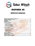
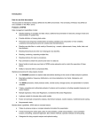
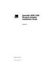
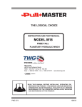
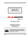
3541RL
SERVICE MANUAL
MODEL CODE .....................................................................................................................................................2
!WARNING!...........................................................................................................................................................3
INTRODUCTION AND THEORY OF OPERATION...........................................................................................4
MAINTENANCE ...................................................................................................................................................4
GENERAL DISASSEMBLY .................................................................................................................................5
A. MOTOR DISASSEMBLY.............................................................................................................................5
B. BRAKE SECTION DISASSEMBLY ............................................................................................................6
C. DRUM & INPUT GEAR SECTION DISASSEMBLY ..................................................................................7
D. OUTPUT GEAR SECTION DISASSEMBLY.............................................................................................8
E. PLANET SET DISASSEMBLY AND ASSEMBLY......................................................................................8
GENERAL ASSEMBLY .......................................................................................................................................9
F. OUTPUT GEAR SECTION ASSEMBLY ....................................................................................................9
G. DRUM & INPUT GEAR SECTION ASSEMBLY ..................................................................................... 10
H. BRAKE SECTION ASSEMBLY ............................................................................................................... 11
I. MOTOR SECTION ASSEMBLY................................................................................................................ 12
TROUBLE SHOOTING..................................................................................................................................... 13
3541RL BILL OF MATERIAL............................................................................................................................ 14
3541RL SUB-ASSEMBLY BILL OF MATERIAL.............................................................................................. 15
VISCOSITY CHART.......................................................................................................................................... 16
TORQUE SPECIFICATIONS CHART ............................................................................................................. 17
G:\SERVICE LITERATURE\3541RL SERVICE LIT\Sel-0005.doc
Rev-0
MODEL CODE
3541RL A L O C D W E
BASIC MODEL
A OR B DRUM WIDTH
LEFT/RIGHT MOUNT
SPOOL OVER/UNDER DRUM
CLOSE COUPLED
MOTOR OPTION
2
!WARNING!
FAILURE TO HEED THE FOLLOWING WARNINGS MAY
RESULT IN SERIOUS INJURY OR DEATH.
1. Tulsa Winches are not to be used to lift, hoist, or move people. If your
task involves lifting or moving people, you MUST use the proper
equipment, not this winch.
2. Cable anchors on Tulsa Winches are not designed to hold the rated
load of the winch. You must keep at least five (5) wraps of cable on the
drum to insure that the cable doesn’t come loose.
3. Stay clear of the suspended loads and of cable under tension. A
broken cable or dropped load can cause serious injury or death.
4. Make sure that all equipment, including the winch and cable, is
maintained properly.
5. Avoid shock loads. This type of load imposes a strain on the winch
many times the actual weight of the load and can cause failure of the
cable or of the winch.
6. Winch operators must be trained in the proper, safe operation of the
winch.
7. Do not use EP type gear lubes in the brake section of this winch. EP
lubes may prevent the clutch from locking up, causing a load to fall, and
resulting in property damage, personal injury, or death.
8. The hydraulic system should use only high quality hydraulic oils from
reputable suppliers. These oils should contain additives to prevent
foaming and oxidation in the system. All winch hydraulic systems
should be equipped with a return line filter capable of filtering 10-micron
particles from the system.
3
INTRODUCTION AND THEORY OF OPERATION
The 3541RL series planetary winch is designed to use a roller-vane gerotor motor, driving through a multiple
disc brake, spring assisted air operated clutch and two planet sets to the cable drum.
The multiple disc brake is spring applied and hydraulically released through a port in the brake housing.
During inhaul, the brake is not released since the load is driven through the one-way cam clutch, bypassing
the brake. When the load comes to a stop, the cam clutch locks up and the load is prevented from moving by
the brake.
The brake and brake valve receives its signal any time the winch is in pay out. With the brake fully open at
about 340 PSI the brake valve will open and dynamically control the lowering of the load.
MAINTENANCE
Tulsa 3541RL series planetary winches, like any other piece of machinery, need to be periodically serviced
and well maintained to insure proper operation.
Good maintenance consists of three steps.
1. A daily inspection to insure that there are no oil leaks present, that all mounting bolts and other fasteners
are tight, and that the wire rope is in good condition.
2. Periodic servicing of the winch includes changing the oil in both the gearboxes and the brake section.
Severity of use will determine the need for oil changes but it should be checked at a minimum of every 500
hours. Factors such as extremely dirty conditions or widely varying temperature changes may dictate
even more frequent servicing.
3. Complete teardowns and component inspections. Again, severity and frequency of use will determine
how often this should be done. If the equipment that this winch is mounted on is subject to standards for
this type of inspection, then those standards must be followed. If oil changes reveal significant metallic
particles then a teardown and inspection must be made to determine the source of wear.
Tulsa 3541RL series of winches are shipped from the factory with SAE 90 EP gear lube in the gearboxes and
automatic transmission fluid in the brake section. This oil should be satisfactory for operation in ambient
temperatures from -10°F to +110°F. If your work calls for operation in temperatures outside this range, contact
Tulsa Winch for recommendations.
Gearbox oil in gear section is drained by removing the fill and drain plugs (items 79) located on the gearbox
cover (item 61). Gearbox oil in the drum section is drained by removing the plug (item 45) located on the
barrel of the drum (item 1). Examine the used oil for signs of significant metal deposits and then dispose of it
in a proper manner. Reinstall the plugs and fill the gearboxes with the proper amount of new SAE 90 EP gear
lube through the fill hole. Make sure the breather (item 78) is operational and replace if necessary.
Drain the brake section by removing the drain plug (item 32) and breather (item 31) in the brake cover (item
28). Inspect the oil for signs of metallic particles and/or burning and re-install the drain plug. Fill brake section
with automatic transmission fluid, or hydraulic oil.
OIL CAPACITIES
GEAR LUBE (DRUM SECTION)
BRAKE OIL
GEAR LUBE (GEAR SECTION)
4
QTY
3/4 qt.
1/2-1 pt.
1-1/2 qts.
TYPE
EP 90
ATF
EP 90
GENERAL DISASSEMBLY
A. MOTOR SECTION DISASSEMBLY
3. Remove the capscrews (item 71) holding
motor in place.
4. Grasp the motor and remove from winch.
5. Inspect o-ring (item 35), replace if necessary.
6. Motors are not serviceable in the field. Return
them to an authorized dealer for service.
1. Drain the oil from the brake assembly by
removing the plug (item 32) from brake cover
(item 28).
2. Remove all tubing and hoses attached to
motor. (Note the location of tubing, hoses and
fittings for re-assembly).
5
B. BRAKE SECTION DISASSEMBLY
1. Evenly remove the four capscrews (item 49)
that hold the brake cover in place. Spring
pressure will raise the cover up as the
capscrews are loosened. Carefully remove
the cover (item 28) from the brake housing
(item 14). Inspect the o-ring (item 36) for
damage and replace if necessary.
2. Remove the springs (item 30) from the piston
(item 29) and check the free height. Each
spring should measure at least 1.250 inches
with no force on them.
3. Remove the brake piston (item 29) by
installing two pieces of 3/8”-16NC all thread
into the two holes in the top of the piston and
run in evenly until the piston is clear of the
housing. An alternate way of removing the
piston is to use a portable hydraulic power unit
or air to gently pressurize the brake cavity to
remove the piston from the brake housing
(item 14).
4. If one or both the square seals (item 51)
remain in the bore of the brake housing,
remove them. Inspect the seals for damage
and replace if necessary.
5. Grasp the brake driver/clutch assembly
(assembled items 34,37,38,39,40,41 & 42)
and remove it from the brake housing.
6. Remove the stator plates (item 25) and friction
discs (item 26) from the brake housing and
7.
8.
9.
10.
11.
6
check them for excessive wear. Replace if
necessary. Be sure to check the top stator
plate for scoring caused by the removal of the
piston and polish if necessary. Friction discs
should measure no less than .055-in. thick and
stator plates should measure no less than
.068-in thick.
To dis-assemble the brake driver/clutch
assembly, remove the retaining ring (item 37)
from either end of the driver. Then remove the
race (item 38) and bushing (item 39). Slide
the brake driver (item 41) off the drive
coupling. (Note: Notice the direction of lockup on the clutch for re-assembly. Inspect the
driver coupling and brake driver for wear.
Replace if necessary.
Remove the retaining ring (item 24), then
remove the middle piston (item 21). Inspect
the seal (item 43) and o-rings (items 20 & 81)
for damage and replace if necessary.
Remove the clutch spring (item 47) and thrust
washer (item 48) from brake housing.
Grasp the sliding clutch (item 27) and remove
from the brake housing.
Remove inner piston (item 17) from brake
housing. Inspect the o-rings (items 18 & 19)
for damage and replace if necessary.
C. DRUM & INPUT GEAR SET DISASSEMBLY
1. Remove all tubing and hoses attached to
motor (item 33) and brake housing (item 14).
(Note the location of tubing, hoses and fittings
for re-assembly).
2. Drain oil from drum section by removing plug
(item 45) located on the barrel of the drum.
3. Then remove the motor and brake assembly
by removing 8 capscrews (item 49).
4. Grasp the motor and remove the motor &
brake assembly from winch.
5. Examine the journal on the brake housing
where the seal (item 13) rides. If severely
worn, replace the brake housing (item 14).
Refer to brake section disassembly section for
brake housing replacement.
6. Grasp the input sun gear (item 44) and
remove from gear set (item 8).
7. Using two crows foot pry bars, hook the
bearing carrier (item 10) in the I.D. of the
bearing (item 12) and pull out of drum. Inspect
8.
9.
10.
11.
12.
7
the seal (item 13), o-ring (item 11) and bearing
(item 12) for damage or wear, replace if
necessary.
Next remove the input gear set (item 8) with
thrust washers (item 9) from drum. Inspect
gear set for wear and repair as needed. (See
gear set disassembly section for disassembly
and assembly procedures).
To remove drum the side plate (item 16) must
be removed by removing capscrews (item 46)
attaching frames to sideplate. Remove side
plate.
Remove drum by hoisting the drum straight up
off of output sun gear (item 15).
Use caution removing drum with cable packer
option (item 64). Cable packer is spring
loaded.
Inspect seal (item 6), bearing (item 5) and
shaft (item 2) located in drum for damage or
wear. Remove and replace if necessary.
D. OUTPUT GEAR SECTION DISASSEMBLY
1. With winch positioned horizontally drain the oil
by removing the plug (item 79) at the bottom of
the gear cover. To disassemble the output
gear end you must start with the outer cover.
Remove the capscrews (item 63) and cover
(item 61).
2. Inspect the o-ring (item 77) and the outer race
(item 7), replace if necessary.
3. Remove output sun gear (item 15), output
gear set (item 60), and the inner race (item 7)
and inspect for Wear. Replace if necessary.
E. PLANET SET DISASSEMBLY AND ASSEMBLY.
1. Remove the retaining rings from the planet
pins.
2. Remove the pins from the carrier by carefully
tapping them out.
3. Remove the planet gears, thrust washers and
bearings from the carriers.
4. Inspect the pins, bearings, and gear bores for
evidence of wear and replace if necessary.
5. Before assembly, be sure to insert the round
thrust plate into the input carrier.
6. To re-assemble, be careful to line up the
planet pins with the thrust washers and
bearings. Press the knurled part of the pin into
the carrier. If the pins are not lined up
properly, the thrust washer can be shattered
during the pressing operation.
7. Replace retaining rings.
8
GENERAL ASSEMBLY
F. OUTPUT GEAR SECTION ASSEMBLY
1. Lubricate and insert inner race (item 7) into
recess located in gear housing (item 80)
2. Insert output gear set (item 15) into gear
housing.
3. Install output sun gear (item 15) into output
gear set.
4. lubricate and install outer race (item 7) into
recess located on output gear set.
5. Install cover (item 61) by installing capscrews
(item 63).
6. Fill gear section to fill/level hole in cover with
proper type of lubricant.
9
G. DRUM & INPUT GEAR SET ASSEMBLY
1. Thoroughly clean all parts. Replace those
which show wear. Lubricate all oil seals and
o-rings before assembly.
2. After inspecting drum, shaft, bearing and seal
for damage or wear, Install drum (item 1) over
output sun gear, making sure that the splines
on shaft (item 2) properly engage output gear
set (item 60).
3. If applicable install cable packer.
4. Install side plate (item 16) by attaching
sideplate to frames with capscrews (item 46).
Note: Do not tighten capscrews (item 46) until
brake housing (item 14) is attached to side
plate (item 16).
5. Lubricate and Insert thrust washer (item 9) into
drum and center over output sun gear (item
15) on top of shaft (item 2).
6. Insert input gear set (item 8) into drum, making
sure that it engages the output sun gear (item
15).
7. Lubricate and Insert thrust washer (item 9) into
drum and locate in recess on input gear set
(item 8).
8. Install the bearing carrier (item 10) with seal
side facing up into drum.
9. Insert the input sun gear (item 44) into input
gear set (item 8).
10. Place the brake assembly into the winch and
install 8 capscrews (item 49).
Tighten
capscrews evenly to 100-110 ft. lb torque.
Make sure that the level and vent plugs in the
cover are properly oriented.
11. Tighten capscrews (item 46) holding frames
(items 22 & 23) to sideplate (item 16).
12. Attach all tubing and hoses to motor (item 33)
and brake housing (item 14).
13. Position winch horizontally and fill drum
section with proper amount and type of
lubricant.
10
H. BRAKE SECTION ASSEMBLY
1. Lubricate and install inner piston (item 17) into
brake housing (item 14).
2. Insert sliding clutch (item 27) into bore of inner
piston (item 17) with long side down.
3. Install thrust washer (item 48), then clutch
spring (item 47).
4. Insert the middle piston (item 21). While
holding down on piston (item 21) install
retaining ring (item 24)
5. Insert the brake driver/clutch assembly,
making sure that it engages the sliding clutch
(item 27).
6. Install the stator plates (item25) and friction
discs (item 26) starting with a stator plate and
alternating between friction discs and stator
plates. There is one more stator plate than
friction discs so you should end with a stator
plate. Note: Soak friction discs in hydraulic oil
before installation.
7. Inspect each new seal (item 51) to make sure
it has an o-ring in the groove of the seal.
Install one seal into the bore of the brake
housing (item 14) with the o-ring side toward
the brake pack. Place the other seal onto the
8.
9.
10.
11.
12.
11
brake piston (item 29) with the o-ring side
toward the flange of the piston.
Lubricate and install piston into the brake
housing and gently tap down until seated.
Install the springs (item 30) into the spring
pockets. If working in a horizontal position,
coat the bottom of each spring with chassis
lube to keep it in position.
Install the brake cover (item 28) onto the brake
housing and tighten capscrews (item 49)
evenly,
alternating
between
opposite
capscrews. Make sure ports are oriented in
proper position.
Check the brake release with a portable
hydraulic pump.
Full release should be
obtained at 320-340 psi. Also, check the
brake for proper operation by applying 280 psi
to the brake port and adapting a torque
wrench to the input shaft. The torque in the
payout direction should be 95-115 ft-lbs.
Check the air operated clutch by applying 100
psi. air to “Clutch In” and “Clutch Out” ports.
Check for leaks and proper working of clutch.
I. MOTOR SECTION ASSEMBLY
1.
Insert motor (item 33) into brake cover (item
28) making sure that ports are oriented
correctly. Install capscrews (item 71) with
lockwashers (item 50).
2. Attach all tubing and hoses.
3. Fill brake section with proper amount of ATF
fluid.
12
TROUBLE SHOOTING
1. PROBLEM:
Winch won’t hold load.
SOLUTION:
a. Excessive back pressure in the system. Check the system for restrictions and reduce the
backpressure.
b. Brake discs are worn out. Replace brake discs.
c. Winch clutch is slipping. Inspect the clutch and driver for wear and replace worn parts.
2. PROBLEM:
Winch will not raise the load it should.
SOLUTION:
a. Relief valve setting may be too low to allow proper lifting. Increase relief valve pressure
setting. (Note: do not exceed recommended system pressures).
b. Load being lifted may be more than the winch’s rating. Reduce the load or re-rig to
increase mechanical advantage.
3. PROBLEM:
Oil leaks from the vent on the motor side of the winch.
SOLUTION:
a. The motor shaft seal may have failed. Replace this seal and reduce backpressure if that
caused the shaft seal to fail.
b. Brake piston seals may have failed. Service the brake section and replace worn parts.
13
3541RL BILL OF MATERIAL
ITEM NO.
PART NO.
QTY.
DESCRIPTION
1
2
3
4
5
6
7
8
9
10
11
12
13
14
15
16
17
18
19
20
21
22
23
24
25
26
27
28
29
30
31
32
33
34
35
36
37
38
39
40
41
42
43
44
45
46
47
48
49
50
51
52
53
54
55
56
57
58
59
60
61
62
63
64
42814
42812
42827
30567
30385
42828
42839
4217
41722
42203
939452
29967
42202
42661
42803
42663
42924
42201
31455
34003
42943
42842
42843
30600
42148
32765
42220
42593
42229
42230
13050
21684
43117
42206
32566
33094
26980
41723
41743
41759
41740
29043
42217
42238
41719
42239
42241
33260
28060
41000
41721
32868
41838
42594
42595
41603
42596
42597
42534
4215
42820
23521
20522
4218
1
1
6
1
1
1
2
1
2
1
1
1
1
1
1
1
1
1
1
1
1
1
1
1
8
7
1
1
1
12
1
1
1
1
1
1
2
2
2
1
1
1
1
1
1
10
1
1
12
4
2
1
1
1
1
1
1
1
1
1
1
1
12
1
DRUM
SHAFT
PIN
RETAINING RING
BEARING, BALL
SEAL, OIL
RACE
INPUT GEAR SET
RACE
CARRIER BEARING
O-RING
BALL BEARING
OIL SEAL
BRAKE HOUSING
OUTPUT SUN GEAR
SIDE PLATE
AIR PISTON
O-RING
O-RING
O-RING
AIR PISTON
FRAME, L.H.
FRAME, R.H.
RETAINING RING
STATOR PLATE
FRICTION DISC
SLIDING CLUTCH
BRAKE COVER
BRAKE PISTON
BRAKE SPRING
BREATHER
PLUG
MOTOR, HYDRAULIC
INPUT DRIVER
O-RING
O-RING
RETAINING RING
RACE
BUSHING
CLUTCH
BRAKE DRIVER
RETAINING RING
OIL SEAL
INPUT SUN GEAR
PLUG, O-RING
CAPSCREW
SPRING, CLUTCH
THRUST WASHER
CAPSCREW
LOCKWASHER
OIL SEAL
ADAPTER, 90 DEG.
ADAPTER, STRAIGHT
MOUNTING BRACKET
TUBING
COUNTERBALANCE VALVE
TUBING
ADAPTER, 90 DEG.
CABLE THIMBLE
OUTPUT GEAR SET
COVER
PLUG
CAPSCREW
CABLE PACKER
14
65
66
67
68
69
70
71
72
73
74
75
76
77
78
79
80
81
42599
42600
40146
21723
21106
42283
42517
42618
42494
42620
42033
41668
42841
4101
32220
42802
41641
1
1
2
2
2
1
4
1
1
1
1
1
1
1
2
1
1
ADAPTER, STRAIGHT
ADAPTER, SWIVEL 90 DEG.
CAPSCREW
NUT
WASHER
CAPLUG
CAPSCREW
ADAPTER, TEE
HOSE ASSEMBLY
ADAPTER, REDUCER
TEE, SWIVEL NUT
CAPLUG
O-RING
BUSHING & BREATHER
PLUG
GEAR HOUSING
O-RING
3541RL SUB-ASSEMBLY BILL OF MATERIAL
SA-4217, INPUT GEAR SET (ITEM 8)
ITEM
DESCRIPTION
QTY.
PART NO.
8-1
8-2
8-3
8-4
8-5
8-6
8-7
INPUT CARRIER
INPUT PLANET GEAR
PLANET PIN
RETAINING RING
PLATE
BEARING
RACE
1
3
3
3
1
3
6
42838
42245
41760
41715
41769
30484
28771
SA-4215, OUTPUT GEAR SET (ITEM 60)
ITEM
DESCRIPTION
QTY.
PART NO.
60-1
60-2
60-3
60-4
60-5
60-6
60-7
OUTPUT CARRIER
PLANET GEAR
PLANET PIN
RETAINING RING
BEARING
SPACER
RACE
1
3
3
3
6
3
6
42805
42806
41747
41716
41717
41739
939249
SA-4218, CABLE PACKER (ITEM 64)
ITEM
DESCRIPTION
QTY.
PART NO.
64-1
64-2
64-3
SPRING, L.H.
CABLE PACKER
SPRING, R.H.
1
1
1
42344
42840
42343
15
VISCOSITY CHART
16
TORQUE SPECIFICATIONS CHART
(HEX HEAD CAP SCREWS)
Nominal Dia.
3/8
7/16
1/2
9/16
5/8
3/4
7/8
1
1-1/8
Threads Per
Inch
16
24
14
20
13
20
12
18
11
18
10
16
9
14
8
14
7
12
17
Grade 5
Grade 8
Ft. Lbs.
Ft. Lbs.
36 - 42
41 - 47
54 - 62
65 - 73
80 - 90
100 - 110
105 - 115
125 - 135
170 - 180
195 - 205
285 - 295
340 - 350
495 - 505
580 - 595
685 - 700
825 - 840
1045 - 1060
1240 - 1260
42 - 48
48 - 54
63 - 71
76 - 84
100 - 110
120 - 130
125 - 135
150 - 160
200 - 210
230 - 240
330 - 340
400 - 410
580 - 595
685 - 700
805 - 820
965 - 980
1500 - 1525
1680 – 1705