1
Ninja ZX-10R
Ninja ZX-10R ABS
2011 Ninja ZX-10R
Racing Kit Manual
This manual contains only the information of the racing kit parts. Refer to the base
manual listed below for information of the original model.
Base Manual
Ninja ZX-10R
Ninja ZX-10R ABS
Motorcycle Service Manual
© 2010 Kawasaki Heavy Industries, Ltd.
Part Number
99924-1443-01
First Edition (0): Dec. 28, 2010
How to Use This Manual
Whenever you see symbols, heed their instructions! Always follow safe operating and
maintenance practices.
DANGER
DANGER indicates a hazardous situation which, if not avoided, will result in death
or serious injury.
WARNING
WARNING indicates a hazardous situation which, if not avoided, could result in
death or serious injury.
CAUTION
CAUTION indicates a hazardous situation which, if not avoided, could result in
minor or moderate injury.
NOTICE
NOTICE is used to address practices not related to personal injury.
This manual contains four more symbols which will help you distinguish different types of
information.
NOTE
○ This note symbol indicates points of particular interest for more efficient and convenient
operation.
z Indicates a procedural step or work to be done.
○ Indicates a procedural sub-step or how to do the work of the procedural step it follows. It
also precedes the text of a NOTE.
Indicates a conditional step or what action to take based on the results of the test or
inspection in the procedural step or sub-step it follows.
1
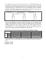
Congratulation on your purchase of racing kit parts for the 2011 Ninja ZX-10R.
IMPORTANT
This manual provides how to install racing kit parts for the 2011 Ninja ZX-10R and
how to tune up basically.
As for the basic knowledge, refer to the base Service Manual for the Ninja ZX-10R
(P/No. 99924-1443-01).
When you participate in a race, it is necessary to modify the machine for the
regulation. So we want you to ask for the tuning up shop.
After any modification to tune the vehicle to a competition machine, it should not
be used on public streets, roads or highways. The use of this vehicle should be
limited to participation in sanctioned competition events upon a closed course.
NOTE
○ When operating the engine, be careful not to trouble persons with noise. Do not turn the
engine with loud engine and exhaust noise.
DISCLAIMER OF WARRANTY
ON OPTIONAL TUNING PARTS FOR RACING ARE NO WARRANTIES EXPRESSED OR
IMPLIED.
BASIC WORKS IN INSTALLING KIT PARTS
We are going to make up the original Ninja ZX-10R for the racing machine. We
recommend that the rider himself should do the basic works, removing parts or installing
parts etc., given advices by the tuning shop. In a race, although trouble will be apt to
happen, if you participate in basic works, you can discriminate cause of trouble, so you can
return the race soon.
But concerning difficult technical works, you should ask to tuning shop.
2
Table of Contents
General Specifications..................................................................................................... 4
Racing Kit Service Data ................................................................................................... 9
Periodic Maintenance Chart .......................................................................................... 10
Preparation ..................................................................................................................... 12
Before Installing .............................................................................................................12
Racing Kit Parts ............................................................................................................. 12
Engine Parts Installation ............................................................................................... 13
Air Intake Parts ..............................................................................................................13
Camshaft Chain Tensioner ............................................................................................ 14
Camshafts, Sprockets, Valve ......................................................................................... 15
Cylinder Head ................................................................................................................17
Cylinder Compression ................................................................................................... 18
Crankshaft Main Journal Bushings ................................................................................ 20
Connecting Rod Bolts .................................................................................................... 22
Connecting Rod Big End Bushings ................................................................................ 23
Clutch Adjustment (Back-Torque Limiter Setting) .......................................................... 25
Transmission.................................................................................................................. 32
Muffler ............................................................................................................................ 34
Radiator ......................................................................................................................... 34
Water Temperature Sensor ............................................................................................ 34
Cover Gaskets (Kit) ....................................................................................................... 35
Oil Catch Tank (Kit) ........................................................................................................ 35
Idle Adjusting Screw (Kit) ............................................................................................... 36
ECU (Kit) ....................................................................................................................... 38
Frame Parts Installation................................................................................................. 40
Throttle Parts (Kit).......................................................................................................... 40
Drive Chain Parts (Kit) ................................................................................................... 42
Brake Pads (Kit)............................................................................................................. 43
Steering Damper (Kit) .................................................................................................... 43
Height Adjustment ......................................................................................................... 44
Front Fork Springs (Kit) ................................................................................................. 45
Electric Parts Installation .............................................................................................. 46
Battery ........................................................................................................................... 46
Main Harness ................................................................................................................ 46
Shift Up Indicator Light .................................................................................................. 46
Handle Switch ................................................................................................................46
Vehicle-down Sensor Installation ................................................................................... 47
Main Harness Installation .............................................................................................. 48
Front/Rear Speed Sensor .............................................................................................. 49
Wiring Diagram ............................................................................................................... 52
3
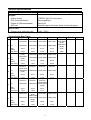
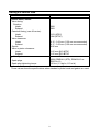
General Specifications
Item
2011 Ninja ZX-10R Racing
Engine:
Ignition timing
Fuel (Recommended)
Engine oil (Recommended):
Oil Level
10°BTDC @1 100 r/min (rpm)
Racing gasoline
Racing oil
Between upper and lower levels of oil level gauge.
Drive Train:
Primary drive reduction ratio
1.681 (79/47)
Transmission Gear Table
Type A
In
1st Out
Teeth
(Out/In)
Gear Ratio
In
2nd
Out
Teeth
(Out/In)
Gear Ratio
In
3rd
Out
Teeth
(Out/In)
Gear Ratio
In
4th
Out
Teeth
(Out/In)
Gear Ratio
In
5th
Out
Teeth
(Out/In)
Gear Ratio
Type B
Type C
Type D
Type E
*13127-0642
13127-0641 13127-0636
[STD]
13262-0615
13262-0626
[STD]
Type F
Type G
-
-
-
-
13127-0638
13127-0639
13127-0640
13262-0664
13262-0624
13262-0625
38/15
31/13
34/14
37/16
39/15
-
-
2.533
13262-0856
[STD]
13262-0880
[STD]
2.385
2.429
2.313
2.600
-
-
13262-0895
13262-0896
13262-0279
-
-
-
13262-0898
13262-0899
13262-0900
-
-
-
37/19
38/18
36/18
-
-
-
2.111
See Gear
Selection
2.000
See Gear
Selection
-
-
-
-
-
-
13262-0643
13262-0644
-
-
-
28/16
36/21
-
-
-
1.714
-
-
-
-
-
-
-
-
-
-
-
-
-
-
-
-
-
-
-
-
-
-
-
-
39/19
2.053
1.947
See Gear
See Gear
Selection
Selection
*13262-0618
(13262-0803) 13262-0642
[STD]
33/19
34/19
1.737
See Gear
Selection
1.789
See Gear
Selection
13262-0645
32/21
1.750
See Gear
Selection
*13262-0646
13262-0619 (13262-0804)
[STD]
31/20
33/21
1.524
1.550
1.571
-
13262-0881
13262-0620 (13262-0648)
13262-0648
[STD]
*13262-0902
13262-0901 (13262-0805) 13262-0903 13262-0904
[STD]
29/21
29/20
28/20
30/21
-
-
-
1.381
1.450
1.400
1.429
-
-
-
4
Type A
In
6th
Out
Teeth
(Out/In)
Gear Ratio
Type B
Type C
Type D
Type E
Type F
Type G
13262-0869
13262-0622 13262-0652
13262-0654 13262-0655 13262-0656 13262-0657
[STD]
13262-0907
13262-0905 13262-0906 (13262-0806) 13262-0908 13262-0909 (13262-0905) (13262-0906)
[STD]
30/23
29/21
31/23
28/22
26/21
30/24
29/22
1.304
1.381
1.348
1.273
1.238
1.250
1.318
(*) in the above table means you need to take care of gear identification etc.
○ The difference between the 1st input shaft type E (13127-0636: Standard), and
13127-0642 is that 13127-0642 is based on the shim adjustment against 13127-0636
(Standard) (Refer to the Transmission Shimming in the Transmission section.). Both
types are different in tooth width, so identify the type by the tooth width. (See the
illustration below.)
○ The difference between the 3rd output gear type A (13262-0803: Standard), and
13262-0618 is that 13262-0618 is based on the shim adjustment against 13262-0803
(Standard) (Refer to the Transmission Shimming in the Transmission section.). Both
types are different in boss width, so identify the type by the boss width. (See the
illustration below.)
5
○ The difference between the 4th output gear type C (13262-0804:Standard), and
13262-0646 is that 13262-0646 is based on the shim adjustment against 13262-0804
(Standard) (Refer to the Transmission Shimming in the Transmission section.). Also, the
4th output gear type B (13262-0619) has no gear identification slit like 13262-0804
(Standard). 13262-0804 (Standard) and racing kit gear are different in boss width, so
identify the type by the boss width. (See the illustration below.)
○ The 5th/6th output gears for the racing kit (13262-0902/13262-0907) have machined
dogs, so that reliability of shifting is improved compared to the standard gears
(13262-0805/13262-0806). By using the 5th/6th output gears with the machined dogs,
reliability of shifting to the 1st to 4th is improved. The 5th/6th output gears have
interchangeability with other standard gears. However, the racing kit gear is
recommended for use in the shifting reliability point of view. Other 5th/6th output gear
types for the racing kit gear have also adopted the machined dogs.
Input 3rd/4th Gear Selection Table, Gear Identification Sulit Number (3rd/4th)
4th Gear
A
B
C
A
13262-0630 (1/1)
13262-0665 (1/0)
13262-0891(0/0) [STD]
B
13262-0633 (2/1)
13262-0632 (2/0)
13262-0634 (2/2)
3rd
C
13262-0638 (0/1)
13262-0637 (0/0)
13262-0639 (0/2)
Gear
-
D
13262-0641 (3/1)
13262-0640 (3/0)
Both the 3rd/4th input gear type A/C (13262-0891:Standard) and the type C/B
(13262-0637) have no gear Identification slits, so identify the type by the number of
teeth.
13262-0891: 19T/21T
13262-0637: 16T/20T
6
Gear Identification Slit Number Table
Type A
1st
2nd
3rd
5th
6th
Type C
Type D
Type E
Type F
Type G
Input
1
2
3
4
0
-
-
Output
1
2
3
4
0 (STD)
-
-
Input
0 (STD)
1
2
3
-
-
-
Output
0 (STD)
1
2
3
-
-
-
-
-
-
Input
Output
4th
Type B
Input
See Gear See Gear See Gear See Gear
Selection
Selection
Selection
Selection
0
1
2
3
-
-
-
-
-
-
-
See Gear See Gear See Gear
Selection
Selection
Selection
Output
1
0
2
-
-
-
-
Input
*2
*2 (STD)
1
2
-
-
-
Output
2
1
0
3
-
-
-
Input
0
1
2 (STD)
3
4
5
6
Output
2
1
0
3
4
2
1
Both the 5th input gear type A (13262-0648) and the 5th input gear type B
(13262-0891:Standard) have two gear Identification slits, so identify the type by the
number of teeth.
13262-0648: 21T
13262-0881: 18T
Shift Forks
13140-0625
When combining the 3rd/4th input racing kit gear with the standard shift fork
(13140-0063), the shift fork interferes with the gear's corner because the chamfer of the
shift fork is small. When using the 3rd/4th input racing kit gear, enlarge the chamfer of
the shift fork, or use the racing kit shift fork (13140-0625). 13140-0625 has enlarged
chamfer compared to 13140-0063 (Standard). See the illustration below.
Output Shaft
13128-0671
When using the 3rd/4th output gear for the racing kit, use the output shaft (13128-0671)
for the racing kit. If the standard output shaft (13128-0670) is used, the shim between the
3rd/4th output gears may fall in the groove of the circlip, resulting in a serious failure.
7
Engine Sprocket
13144-0021 #520-16T
13144-0022 #520-17T
8
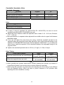
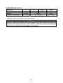
Racing Kit Service Data
Item
Standard
Cylinder Head, Valves:
Valve timing:
Duration:
Intake
Exhaust
Camshaft timing (cam lift center):
Intake
Exhaust
Valve clearance:
Intake
Exhaust
Squish
Valve to piston clearance:
Intake
Exhaust
Ignition System:
296°
293°
112° (ATDC)
104° (BTDC)
0.15 ∼ 0.22 mm (0.20 mm recommended)
0.17 ∼ 0.22 mm (0.20 mm recommended)
0.85 mm
1.65 mm @10°ATDC
1.65 mm @10°BTDC
NGK CR9EIA-9 (STD), R0045Q-10 or
R0373A-10
13 N⋅m (1.3 kgf⋅m, 113 in⋅lb)
Spark plugs
Spark plug tightening torque
These values show the specifications when standard cylinder head and gasket are used.
9
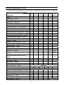
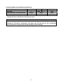
Periodic Maintenance Chart
The scheduled maintenance must be done in accordance with this chart to keep the
motorcycle in good running condition.
FREQENCY Each
Every
Every
Every
Race
2races
3races
5races 10races Required
OPERATION
Every
As
Engine
Clutch plate - - check*
●
Throttle grip play - - check*
●
Spark plug - - clean/gap*
●
Engine oil - - change
●
Oil filter - - replace
●
Cylinder head/valve - - decarbonization
●
Cylinder - - check*
●
Piston/cylinder clearance - - check*
●
Piston ring, piston, and piston pin - - replace
●
Crankshaft main bearing - - check*
●
Connecting rod big end bearing - - check*
●
Transmission gear, bearing - - check*
●
Engine sprocket - - check*
●
Coolant - - change
Radiator hoses, connections - - check*
●
●
Frame
Brake operation - - check*
●
Brake pad wear - - check*
●
Brake fluid level - - check*
●
Brake fluid - - change*
year
Brake master cylinder cup and dust seal - -
year
replace
Brake caliper piston seal and dust seal - -
year
replace
Brake hose - - replace
2 years
Drive chain - - adjust
●
Drive chain - - lubricate
●
Drive chain wear - - check*
●
Drive chain guide - - replace
Front fork - - clean/check*
If damaged
●
Front fork oil - - change
First change after 2 races, then every 5 races
Nut, bolt, and fastener tightness - - check*
●
Fuel system - - clean
●
Fuel hose, fuel filter - - replace
Steering play - - check*
●
●
Steering stem bearing - - grease
●
Rear sprocket - - replace
●
10
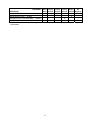
FREQENCY Each
Every
Every
Every
Race
2races
3races
5races 10races Required
OPERATION
General lubrication of chassis - - perform
Every
As
●
Wheel bearing (rear) - - grease
●
Swingarm pivot, uni-track linkage - - grease
●
Swingarm pivot, uni-track linkage - - check*
●
(*) in the above table means you need to replace, add, adjust, clean, or torque if
necessary.
11
Preparation
Before Installing
Modify the parts based on your race regulation.
To avoid misuse keep the parts replaced with the kit parts separate.
When reusing parts, clean them and check them for damage or deterioration.
Main Removal Parts:
Lights
Rear View Mirrors
Side Stand
Starter Lockout Switch
z Remove the side stand switch. When the optional main harness is not used, connect
removing Black/Yellow and Green/White Leads directly.
z
z
z
z
Racing Kit Parts
Also, we have provided the spare parts, and other optional parts (engine, frame, and
electric parts) for racing. So please order each parts referring to the “Racing Kit Parts List”
in the back of this manual.
12
Engine Parts Installation
Air Intake Parts
z Remove the air cleaner element or cut the cleaner element off remaining the air cleaner
element plate to reduce the air flow resistance.
1. Relational Parts of Secondary Air: Remove the Parts.
2. Remove the parts or cut the cleaner element off remaining the air cleaner element
plate.
3. Secondary Air Passages on Cylinder Head: Plug the holes, or press-fit the plugs
(92066-1005) instead of the original pins.
Output of Secondary Air on Air Cleaner: Plug the hole
4. Air Cleaner Drain Tube: Use it cutting it in suitable length.
13
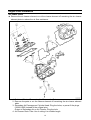
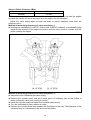
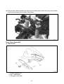
Camshaft Chain Tensioner
z Replace the cam chain tensioner with the kit to decrease the flutter of tensioner.
z Apply the engine oil to the tensioner rod, O-ring and tensioner body, insert them into the
tensioner body.
○ Check to see that the tensioner rod turns freely in the body, if not, polish the tensioner
rod or fine the female threads in the body with a tap (Diameter × Pitch = 6 mm × 1.0 mm).
z Install the tensioner on the cylinder block with the tensioner rod is fully pushed back.
z Turn the tensioner rod in with a screwdriver until it becomes hard to turn.
z Turn the crankshaft clockwise forcing lightly to the tensioner rod with twisting force to
take up any gap and tighten the locknut.
NOTICE
Never forward the tensioner rod forcibly, this will increase mechanical loss of the
tensioner and may damage to the chain guide.
The cam chain tensioner must be adjusted at every race.
1. Tensioner Body
2. Tensioner Rod
3. O-ring
4. O-ring
5. Locknut
14
Camshafts, Sprockets, Valve
Camshafts, Sprockets:
Camshaft
49118-0718 (STD) (Intake)
49118-0719 (STD) (Exhaust)
49118-0728 (Kit) (Intake)
49118-0729 (Kit) (Exhaust)
Duration
296°
293°
301°
306°
Lift
10.3 mm
9.1 mm
10.5 mm
9.1 mm
Valve:
Valve
12004-0044 (STD) (Intake)
12005-0059 (STD) (Exhaust)
z In case of using kit camshaft (IN: 49118-0728, EX: 49118-0729), be sure to use kit
camshaft sprocket (IN/EX: 12046-0034) as a set.
z Adjust the valve clearance within the specified value. Intake: 0.15 ∼ 0.22 mm, Exhaust:
0.17 ∼ 0.22 mm
○ More performance is expected when adjusted from middle value to upper limit between
adjustable range.
z If you can not adjust the valve timing for racing, install the camshaft sprocket to the
camshaft using the round bolt holes and adjust the cam chain timing according to the
attached “ZX1000JBF/KBF Motorcycle Service Manual: 99924-1443”. If you adjust the
valve timing, install the sprocket to the camshaft between the adjustable range of the
long bolt holes.
z Tighten the camshaft sprocket bolts to 15 N⋅m (1.5 kgf⋅m, 11 ft⋅lb) of torque.
Valve Timing
Timing (cam lift center)
Intake
112°
When the round bolt holes are used (Original)
(Original camshaft)
113°
When the long bolt holes are used
(Kit camshaft)
Exhaust
104°
(Original camshaft)
108°
(Kit camshaft)
NOTE
○ When grinding the cylinder head bottom surface, grinding the cylinder top surface or
using thinner gaskets, be sure the valve to piston clearance especially.
○ When using the sprocket long bolt holes and adjusting the valve timing to be different
from the standard timing, check the valve to piston clearance of all cylinders after
adjusting the valve clearance correctly.
15
Valve to Piston Clearance (Min.)
Intake
0.7 mm
Exhaust
1.2 mm
If the valve to piston clearance is less than the minimum value, do not start the engine
because the valves will touch the piston and the engine may be damaged.
Adjust the valve timing again to keep the valve to piston clearance more than the
minimum value.
Method of measuring clearance of valve and piston –1
z Holding the crankshaft at 10°ATDC (intake) and 10°BTDC (exhaust) of crankshaft timing,
measure the amount of the tappet movement until the valve comes in contact with the
piston pushing the tappet.
Method of measuring clearance of valve and piston –2
z Adjust the valve clearance and valve timing.
z Remove the cylinder head, and put a small piece of modeling clay on the hollow of
piston to prevent valve from coming in contact.
z Install the cylinder head and adjust the camshaft chain timing.
z Turn the crankshaft by two rotations or more.
z Remove the cylinder head and measure the thickness of the clay. The thickness of the
collapsed clay is a clearance of the valve and the piston.
16
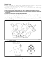
Cylinder Head
z Before reassemble the cylinder head grind off the stepped portions of the port and
smooth the inside of ports to make intake/exhaust gas flow smooth.
○ Grind off the stepped portions only at the mating surface between the throttle body
holder and the intake port.
○ Mark the throttle body holders so that they can be installed in their original positions.
○ Grind off and smooth the stepped portions at the mating surface between the valve seat
and the port.
○ Smooth the inside of the intake port and exhaust port.
z Chamfer the machining edge of the cylinder head where the valve seat installed, also
smooth the dome of the combustion chamber with the valves installed. Excessive
smoothing may reduce the cylinder compression.
○ Use the hand grinder. Use #200 oil stone for eliminating any stepped portion and #300
oil stone for finishing.
A: Stepped Portions
17
NOTE
○ These procedures make air resistance less and intake/exhaust gas flow more smooth.
However, much more effect cannot be expected by excessive grinding and smoothing. It
may be done to the extent of getting rid of uneven surfaces.
Cylinder Compression
○
z
z
z
z
To adjust the cylinder compression, adjust the thickness of the cylinder head gasket or
smooth the cylinder head under surface or cylinder top surface to make the piston
squish 0.65 mm. Keep the piston squish more than 0.65 mm.
Grind off the cylinder head under surface to 0.1 ∼ 0.4 mm. Do not grind the cylinder
upper surface. This can raise the compression ratio while keeping the clearance of the
piston and valve, and one of the squish. Although, as the engine machining is uneven,
determine the cutting dimension after confirmation the recess and the squish before
machining. With the compression ratio rise, the maximum horsepower increases while
handling of the throttle in the slight opening range tends to become harder. It is
recommended to drive with only squish adjustment by the gasket without grinding the
cylinder head at first.
Position the piston at Top Dead Center, and put a small piece of modeling clay on the
shoulder of the piston. Install the cylinder head gasket and cylinder head, and tighten the
head bolts to the specified torque.
Remove the cylinder head and measure the thickness of the clay. The thickness of the
collapsed clay is the size of the squish.
The most preferable squish measurement is 0.65 mm.
Select proper cylinder head gasket.
18
Cylinder Head Gasket
Part No.
11004-0719
11004-0720
11004-0721
11004-0722
Tightening thickness
0.65 mm (STD)
0.60 mm
0.55 mm
0.50 mm
Remarks
KIT
KIT
KIT
KIT
ID Number
65
60
55
50
○ As for the cylinder head casket of the racing kit, oil supply hole to the cam is smaller than
the standard one to change the fuel distribution in the engine. For circuit riding, it is
recommended to use the cylinder head gasket for the racing kit even when using the
standard thickness cylinder head gasket.
NOTE
○ When grinding the cylinder head lower surface or using thinner gasket, adjust the valve
timing to keep that the valve to piston clearance is not less than the minimum value (IN:
0.7 mm, EX: 1.2 mm).
19
Crankshaft Main Journal Bushings
The kit bushings are improved in anti-seizuring characteristics as well as in
wear-resistance as compared with the standard bushings.
Crankshaft Main Journal Clearance
When adjust the clearance by measurement in case
aiming the clearance 0.035 mm.
Crankshaft Main Journal Diameter Marks
None: 34.984 ∼ 34.992 mm
1:
34.993 ∼ 35.000 mm
Crankcase Main Bearing Inside Diameter Marks
:
38.000 ∼ 38.008 mm
None: 38.009 ∼ 38.016 mm
Mark portion: #1 ~ 5
[A]: Size Color
Crankshaft Main Journal Bushings
Color
Kit Bushing
#1, 3, 5
Kit Bushing
#2, 4
Standard
Bushing
#1, 3, 5
Standard
Bushing
#2, 4
Thickness
Blue
92139-0746
92139-0750
92139-0298
92139-0301
1.499 ∼ 1.503 mm
Black
92139-0747
92139-0751
92139-0299
92139-0302
1.495 ∼ 1.499 mm
Brown
92139-0748
92139-0752
92139-0749
92139-0753
92139-0303
−
1.491 ∼ 1.495 mm
Pink
92139-0300
−
20
1.487 ∼ 1.491 mm
Crankshaft Main Journal Bushing Selection
Crankshaft
1
1
None
None
Crankcase
None
None
Crankshaft Main Journal Bushing
Brown
Black
Blue
Clearance (recommend)
10 ∼ 34 µm
10 ∼ 34 µm
10 ∼ 34 µm
Use the pink bushings when the clearances cannot adjusted within the prescribed
allowances even if the brown bushings are used.
NOTICE
Make the clearances between the crankshaft main journals within the prescribed
allowances. Excessive clearances will cause the oil pressure at the crankshaft
main journals to drop and lead to the damage of the bearing.
21
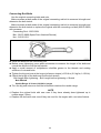
Connecting Rod Bolts
Use the original connecting bolts and nuts.
Make recesses at both ends of the original connecting rod bolt to measure its length and
determine the bolt stretch.
Make recesses at both ends of the original connecting rod bolt to measure its length and
determine the bolt stretch or replace the original with the connecting rod bolt (92513-0809)
with recesses.
Connecting Rod :13251-0031
Bolt : 92153-0809 (Spare Part: Attached Recess)
Nut : 92015-1311
z Install the bolts into the connecting rod.
z Before every tightening, use a point micrometer to measure the length of the bolts and
record the values to find the bolt stretch.
z Apply a small amount of molybdenum disulfide grease to the threads and seating
surfaces of nuts and bolts.
z Tighten the big end nuts at the torque (reference torque) of 20 N⋅m (2.0 kgf⋅m, 14.5 ft⋅lb).
z Check the length of the bolts and find the bolt stretch.
Bolt Length after tightening – Bolt Length before tightening = Stretch
Bolt Stretch
Usable Range: 0.32 mm (0.0126 in.) target
z Turn the big end nuts more until the bolt stretch reaches the usable range.
NOTE
○ Replace the original bolts with new ones if they have already been tightened up to
usable range 2 times.
○ Replace the bolts with new ones if they are used for the engine with a not clear feature.
22
Connecting Rod Big End Bushings
The connecting rod bushing in the kit has improved its anti-seizure feature than standard
one.
Connecting Rod Big End Bushing/Crankpin Clearance
○ When adjust the clearance by measurement in case aiming the clearance 0.050 mm.
Crankpin Diameter Marks
: 34.493 ∼ 34.500 mm
None: 34.484 ∼ 34.492 mm
Connecting Rod Big End Bore Diameter Marks
:
37.509 ∼ 37.516 mm
None: 37.500 ∼ 37.508 mm
[A]. Diameter Mark ( or no mark)
[B]. Weight Mark (Alphabet, E, F etc)
[A]. Size Color
Connecting Rod Big End Bushings
Color
Blue
Black
Brown
Pink
Kit Bushing Part
Number
92139-0754
92139-0755
92139-0756
92139-0757
Original Bushing
Part Number
92139-0719
92139-0720
92139-0721
−
23
Thickness
1.488 ∼ 1.493 mm
1.483 ∼ 1.488 mm
1.478 ∼ 1.483 mm
1.473 ∼ 1.478 mm
Big End Bushing Selection
Crankshaft
None
None
Connecting Rod
None
None
Bushing
Brown
Black
Blue
Clearance (recommend)
30 ∼ 60 µm
30 ∼ 60 µm
30 ∼ 60 µm
○ Use the pink bushings when the clearances cannot adjusted within the prescribed
allowances even if the brown bushings are used.
NOTICE
Make the clearances between the connecting rod big ends within the prescribed
allowances. Excessive clearances will cause the oil pressure at the connecting rod
big end to drop and lead to the damage of the bearing.
24
Clutch Adjustment (Back-Torque Limiter Setting)
The Ninja ZX-10R engine is equipped with the Kawasaki back-torque limiter mechanism
in the clutch. The back-torque limiter works to reduce the chance of rear wheel hop caused
by heavy engine braking and down shifting. The back-torque limiter operating condition can
be changed by changing the total thickness of clutch plates and changing the number of
leaf springs. Try different settings and select the best.
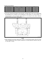
The standard setting of length [A], total thickness of clutch plates shown below, becomes
about 53.5 mm (t 2.9 × 7 pcs. + t 2.6 × 2 pcs.). For this setting the effective stroke of clutch
spring plate during the back-torque limiter operation is adjusted between 0.45 and 0.75
mm.
By increasing the effective stroke the back-torque limiter causes more slip. The
effective stroke increases by decreasing the length [A]. The length [A] between 51.9 and
53.5 mm is available by changing the combination of the steel plates. Replace one steel
plate with a thinner one and try the setting. If the operation of the back-torque limiter is not
enough replace other steel plates one by one.
Thickness (mm)
2.3
2.6
2.9
Part Number
13089-0008 (STD)
13089-0009 (STD)
13089-1093 (STD)
25
z When decreasing the length [A], total thickness of clutch plates, use the kit spring
retainers (provided as optional production parts) to keep the preload of clutch springs
according to the table below.
Length [A]
Part Number
53.0 ∼ 53.5 mm
13091-1840 (STD)
13091-1041 + Washer (92022-304)
39108-0005
13091-1041
52.5 ∼ 52.9 mm
51.9 ∼ 52.4 mm
Height [H]
8 mm
7 mm (6 mm + 1 mm)
7 mm
6 mm
If you have clutch slip during acceleration use shorter spring retainers by one size to
increase preload of clutch springs.
26
z For precise setting the measurement of the effective stroke of clutch spring plate is
recommended.
○ Remove oil from clutch plates.
○ Hold an extra drive shaft in a vise and install the following clutch parts on the shaft.
[A] Collar
[B] Needle Bearing
[C] Bushing
[D] Clutch Housing
[E] Spacer
[F] Clutch Hub
[G] Sub Clutch Hub
[H] Friction Plates (48 Slots): 2 Plates
[I] Washer
[J] Judder Spring
[K] Friction Plates (36 Slots): 8 Plates
[L] Steel Plates (t 2.9 mm): 7 Plates
[M] Steel Plates (t 2.6 mm): 2 Plates
[N] Spring Retainer
[P] Spring Retainer
27
z Engage the cam followers (Clutch Hub) with the cams (Sub Clutch Hub).
z To measure the effective stroke of clutch spring plate, set a dial gauge [A] against the
center [B] of the clutch spring plate.
z Move the clutch housing gear back and forth [C]. The difference between the highest and
lowest gauge readings is the amount of the effective stroke of clutch spring plate.
[D] Drive Shaft
28
z After installing the clutch to the engine, measure and record the depth [B] shown below,
the length from the clutch spring plate to the top surface of the sub clutch hub, using a
caliper or a depth gauge. Manage the depth [B] to adjust the effective stroke after that,
because the friction disks would be worn and the length [A] would change. The decrease
of the depth [B] from the initial setting shows the increase of the effective stroke of clutch
spring plate from the value initially measured.
29
Spring Plate Assembly
The racing kit includes the spring plate assembly to cope with a judder at startup.
Remove the judder spring, washer, and innermost steel plate [refer to [C] (above figure)]
installed in ’11ZX-10R, and replace them with the spring plate assembly.
There are three types of the spring plate assembly with different spring load.
Decide which one to be used depending on the condition of a judder at startup.
When adjusting, be careful of the length [A] (above figure) because the plate thickness is
different by the type.
Measure the length of the spring plate assembly with the spring stuck together by using a
vice.
The standard thickness and number of the spring plate are as follows. Adjust as necessary.
Spring plate 2.6mm : 8pcs …13089-0003
Part Number
13089-0003
13089-0011
13089-0012
Spring Constant
Standard
40% up comparison standard
60% up comparison standard
ID Color
None
White
Blue
Identification Color: The ID marks are on the springs between the steel plates.
30
[A]
[B]
[C]
[D]
[E]
[F]
Collar
Needle Bearing
Bushing
Clutch Housing
Spacer
Clutch Hub
[G] Sub Clutch Hub
[H] Friction Plates
[I] Spring Plate Assembly
[J] Steel Plates
[K] Spring Plate
[L] Spring Retainer
31
Transmission
The 2011 model ZX-10R adopts the cassette transmission and the gears can be changed
with the engine equipped. For the engine assembly and disassembly, refer to the attached
"ZX1000JBF/KBF Motorcycle Service Manual:99924-1443".
z Type A ∼ G of the kit gears are available of the racing kit. To change the gear ratios with
combination the gears. The output shaft and 5th output gear for the racing kit have no
space to install of the steel balls.
z Remove the three steel balls (600A0500) from the output shaft assembly. This is done to
start easily the engine with the second gear. The output shaft and 5th output gear for the
racing kit have no space to install of the steel balls.
z Replace the circlips with new ones if they were removed.
Transmission Shimming
By using washers with various thickness, keep the axial clearance between 0.3 mm and
0.4 mm, to prevent the inclination of gears and to keep smooth gear-shifting.
1 Spline washer 1
2 Spline washer 2
3 Plane washer
Thickness (mm)
Part No.
Remarks
1.2
1.4
1.6
1.8
2.0
2.6
2.8
3.0
0.8
1.0
1.2
1.4
1.6
92200-0229
92200-0230
92200-0050
92200-0231
92200-0232
92200-0748
92200-0749
92200-0750
92200-0225
92200-0226
92200-0051
92200-0227
92200-0228
Kit
Kit
Original
Kit
Kit
Kit
Kit (STD)
Kit
Kit
Kit
Kit (STD)
Kit
Kit
32
Use the kit input shafts of the racing kit with the washer adjustment since their sizes are,
different from the standard shaft, designed taking the washer adjustment into account in
order to make the dog lengths of the 3rd-5th & 2nd-6th input gear dogs equal. Adjust the
dog length of each gears to smooth gear-shifting to the 5th and 6th gear.
Standard Adjusting
A-2 Use the standard spline washer t 2.8 mm (92200-0749)
B-2 Use the standard spline washer t 1.2 mm (92200-0051)
When thin the washer of A-1 (B-1) from the standard washer and thickly the washer of A-2
(B-2) from the standard washer to increase the dog length of gears.
Use the kit input shafts of the racing kit with the washer adjustment since their sizes are,
different from the standard shaft, designed taking the washer adjustment into account in
order to make the dog lengths of the 3rd – 5th & 2nd – 6th input gear dogs equal. Adjust the
dog length of each gears to smooth gear-shifting to the 3rd and 4th gear.
Standard Adjusting C-1⋅C-3 Use the standard spline washer t 1.6 mm (92200-0050).
Thinner washer for C-1⋅C-3 increases the dog length. Adjust the axial clearance at C-2.
33
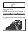
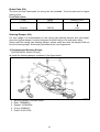
Engine Sprocket
When using the engine sprocket for the racing kit, combine it with the dedicated collar and
be careful of the direction of the sprocket. Install the sprocket so that the teeth number mark
("16" or "17") faces to the outside of the body.
A: Engine Sprocket 13144-0021(16T) or 13144-0022(17T)
Install the sprocket so that the teeth number mark ("16" or "17") faces to the outside of
the body.
B: Dedicated Collar 92152-1522
with identification groove
Muffler
With recommended muffler engine performance can be improved.
Recommended muffler: LeoVince
Home Page
: http://www.leovince.com (LeoVince)
○ For further information contact the manufacture of muffler directly.
Radiator
2011 model ZX-10R racing kit provides the recommended radiator to improved the
cooling function.
Recommended radiator: Taleo Tecnoracing-made
Home Page
: http://www.taleotecnoracing.com
○ For further information about the radiator, contact the manufacturer directly.
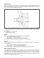
Water Temperature Sensor
The original water temperature sensor installed in the cylinder head must be remain and
connected to the main harness because the electronic control unit (E.C.U.) needs the
output signal from the original water temperature sensor. Be sure to connect the water
temperature sensor to the main harness (either race kit main harness for race kit E.C.U or
original main harness for original E.C.U).
34
Cover Gaskets (Kit)
The kit cover gasket are available of the 2011 model ZX-10R.
They are made from “metal-foam” and made easy to separate.
Alternator Cover: 11061-0755
Clutch Cover: 11061-0754
Crankshaft Sensor Cover: 11061-0756
Oil Pan: 11061-0757
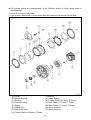
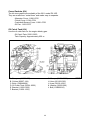
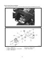
Oil Catch Tank (Kit)
Use the oil catch tank for the engine blowby gas.
Oil Catch Tank: 52001-0553
Tank Capacity: Approximately 650 cc
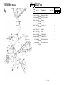
A. Dampers (92075-277)
B. Collars (92027-194)
C. Bolts (130BA0620)
D. Oil Catch Tank (52001-0553)
E. Bracket (11056-1233)
F. Bracket (11056-1232)
G. Clamps (92171-0338)
H. Hose (92192-1025)
J. Hose (92192-1026)
K. Washer (92022-304)
L. Bolt (130BD0610)
35
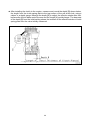
Oil Catch Tank Installation
z Temporarily tighten the mounting bracket [E] together with the chain cover.
z Tighten the mounting bracket [F] together with the starter cove.
z Install the damper [A] and collar [B] on the bracket of the tank [D] and fix them to the
bracket [E] and [F] with the bolt [C].
z Tighten the mounting bracket [E].
z Cap the draining boss of the oil catch tank with the M6 bolt [L] and washer [K] and wire to
prevent them from falling out.
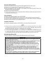
Hose Installation
z Remove the original breather hose (92192-0889).
z Install the hose [J] between the air cleaner and oil catch tank by using the clamp [G].
z Install the hose [H] between the crankcase and the oil catch tank by using the clamp [G].
z Run the hoses as shown in the illustration above.
Regulator Installation
z Install the standard regulator (21066-0028) on the tank [D] with the bolt [C].
NOTE
○ Protect the hose and check the no blockade at the its curved part when the hose is afraid
of interfering with edge part on the way of the hose routing. Specially, about the hose
toward the crankcase, check the no blockage by the fuel pump.
○ For the oil catch tank installation, it is necessary for the ABS(KIBS) equipped motorcycle
to remove the ABS unit so that the brake hose routing is the same as the ABS(KIBS)
non-equipped motorcycle. Be fully aware that the ABS does not work in this case.
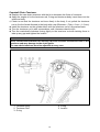
Idle Adjusting Screw (Kit)
The 2011 model ZX-10R provides the idle adjusting screw as the racing kit.
WARNING
This idle adjusting screw works properly only when it is used together with the
racing kit ECU (21175-0737).
This idle adjusting screw cannot work properly with the standard ECU because
the idle control program and fuel-cut program in deceleration etc are
incorporated in the ECU. Moreover, unexpected failure may happen, which
leads to a serious accident. Never use this idle adjusting screw together with
the standard ECU.
Idling engine speed and engine characteristics in full-closing throttle can be
changed by changing the racing kit ECU setting without using this idle
adjusting screw. Use the idle adjusting screw supplementarily only when the
racing kit ECU cannot adjust enough. For the deatils, refer to the racing kit ECU
instruction manual.
Be careful when adjusting to increase engine speed. If the engine speed does
not decrease enough, excessive speed may lead to a serious accident.
36
A. Stopper (Original)
B. Locknut (Original)
C. Idle Adjust Screw Set (16021-0055)
D. Stopper (Kit)
E. Locknut (Kit)
F. Spring
G. Adjust Screw (92172-0745)
H. Remote Adjusting Screw (92172-0746)
Idle Adjusting Screw (Kit) Installation
z Before the installation, check if the input/output voltage is within the proper range. For the
confirmation, refer to the attached "ZX1000JBF/KBF Motorcycle Service Manual:
99924-1443".
z Put a cloth between the throttle valve and body to prevent the throttle valve from
interfering with the body.
z Remove the standard stopper [A] and lock nut [B].
z Install the stopper of the kit [D]. Tighten enough the stopper so that the throttle valve
does not interfere with the body when removing the cloth.
z Remove the cloth and adjust the stopper [D] position so that the output voltage is within
the proper range (DC 0.645∼0.675 V). Fix it with the lock nut [E].
z Install the spring [F] and adjusting screw [G]. The adjusting screw [G] can be replaced
with the remote adjusting screw [H] if necessary.
z When decreasing the idling engine speed, always use the adjusting screw in contact with
the throttle pulley. (The stopper does not contact throttle pulley.)
37
ECU (Kit)
The 2011 model ZX-10R kit ECU has following functions. Refer to the “Kawasaki FI
Calibration Tool Instruction Manual: 99929-0549-01” for the ECU function set up
method.
1. Auto Shift Functions
Be sure use the point type sensor.
Recommended: Dynojet made or Battle Factory made
2. Pit lane Engine Revolution Limit Functions
The speed control function is activated by pushing the turn signal switch.
3. Shift Indicator Functions
The standard meter can be used as the shift up indicator. The shift up indicator light
can be used together with it or whichever can be used
4. Launch Control Functions
The engine revolution limit can be set at start up
5. Engine Brake Control Functions
By setting the ISC opening angle, the engine characteristics can be adjusted when
the engine brake is applied
6. Traction Control Setting Functions
The traction control S-KTRC setting can be changed. Any three modes can be
selected from the preset 33 modes and can be switched during riding (3 modes +
OFF).
7. Power Mode Setting Functions
In addition to the engine brake control mentioned above, the fuel injection
compensation, fuel compensation in acceleration, ignition timing correction, and
subthrottle opening correction etc can be set in three modes independently. Any
three preset modes can be switched during riding.
○
○
○
○
NOTE
The racing kit ECU does not operate excluding the combination with the racing kit
harness (26031-1219). For the kit harness installation, refer to "Electric Parts
Installation" in this manual.
The kit ECU can be installed on both ABS(KIBS) equipped/non-equipped motorcycles by
using the kit harness. However, the ABS stops functioning. There is no ABS-compliant kit
ECU. Be fully aware that the ABS does not work and drive carefully when the kit ECU is
installed on the ABS(KIBS) equipped motorcycle.
In circuit racing on ABS(KIBS) equipped motorcycle without the racing ECU, be fully
aware as follows:
The ABS is designed to prevent wheel lock when the brakes are suddenly applied in
straight running.
The ABS is not designed to shorten the braking distance. The braking distance can be
longer in the ABS equipped motorcycle than in non-equipped motorcycle on slipperly ,
rough, or downhill road surface. Drive carefully on such road conditions.
38
WARNING
ABS(KIBS) cannot protect the rider from all possible hazards and is not a
substitute for safe riding practices. Be aware of how the ABS(KIBS) system
operates and its limitations. It is the rider's responsibility to ride at appropriate
speeds and manner for weather, road surface and traffic conditions.
39
Frame Parts Installation
Throttle Parts (Kit)
The following throttle cases, grip and reels are available as optional parts. These optional
parts quicken throttle response to the throttle grip.
1) Throttle Case
Parts Name
Throttle Case, Upper
Throttle Case, Lower
Bolts (2)
Grip
P/No.
32099-0046
92099-0047
120CA0518
31064-0187
2) Throttle Reels
Tow types are available.
Throttle Reel Travel Angle················Effective angle excluding throttle cable free play.
P/No.
I.D. Mark
59101-0008
59101-0009
R19.7/65deg
R21.4/60deg
Throttle Grip Turn Angle
to Full Throttle
65°
60°
○ The throttle cases, throttle pipe and reels are interchangeable with those of ’10 model.
1. Identification Mark
1. Upper Case: 32099-0046
2. Lower Case: 32099-0047
3. Bolts: 120CA0518
4. Reel (65°): 59101-0008
5. Reel (60°): 59101-0009
6. Grip: 31064-0187
40
z Assemble the throttle cases so that the identification groove faces upwards (see above).
○ It is correct to assemble the throttle cases so that the groove side have no clearance and
the opposite (lower) side have clearance.
3) Throttle Cable
Accelerator and decelator cables are the same. It is possible to use the cable even if the
cable is installed on either the accelerator side or decelator side because the cable of the
same length is used.
Part Name
P/No.
I.D. Mark
Throttle Cable
54012-0276
12-0276-xxxx
○ The throttle cable is newly designed for ’11 model and incompatible with the kit parts
for ’10 model.
See the illustration below for installation.
z Run the accelerator cable over the master cylinder and run the decelator cable under the
master cylinder.
41
z Run the both cables between the left side of the head pipe and the front fork and connect
it to the throttle body from the left of the frame.
Drive Chain Parts (Kit)
1) Chain Guard
1. Guard: 55020-0795
2. Bolt: 130BA0820
3. Swingarm (Left Side)
42
Brake Pads (Kit)
The front and rear brake pads for racing use are available. The front pads are for higher
braking force.
Front Brake Pads
P/No.
43082-0088
Original
Stamp
F9633
Braking Force
High
C93YW
Low
Steering Damper (Kit)
For race usage it is recommended to use racing type steering damper (see next page),
since the original damper is mainly designed for street riding or at most sport riding.
When install the racing type steering damper, please make sure that the damper shall not
limit the steering angle, as normally stipulated by the race regulations.
1) Recommended Steering Damper
OHLINS SD001 (Stroke: 68 mm)
z Install the steering damper as shown in the figure below.
1.
2.
3.
4.
5.
Steering Damper:OHLINS SD001
Bolts:130BA0830
Washer:410AA0800
O-ring:670B2012
Collar: 92152-0798
43
Height Adjustment
z Remove the nut [1] and replace the nut with a new one.
z Insert the spacer [2] as required.
z Tighten the new nut [1] to 59 N·m (6.0 kgf·m, 43 ft·lb) of torque.
1. Nut:92015-1316 (Standard)
2. Spacer Set:92026-0724
3. Bracket:32037-0149 (Standard)
Spacer Set: 92026-0724
P/No.
92026-0721
92026-0722
92026-0723
Quantity
3
3
3
Thickness
1.0 mm
2.0 mm
3.0 mm
44
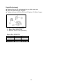
Front Fork Springs (Kit)
The optional front fork springs are available for racing.
1) Front Fork Spring
P/No.
Original
44026-0163
44026-0164
Spring Constant
K = 10.25 N/mm
K = 9.75 N/mm
K = 10.75 N/mm
2) Front Fork Spring Replacement
Replace the main spring referring to the Fork Oil Change section of the base Service
Manual “ZX1000JBF/KBF Motorcycle Service Manual: 99924-1443”.
Identification Mark
The identification slit for a spring constant valve is stamped on the one end face of the
spring.
45
Electric Parts Installation
Battery
Use the original battery or a battery with 12 V 6 Ah or more capacity.
Main Harness
Main harness (26031-1219) is available for racing use as a kit.
The kit ECU does not operate excluding the combination with the kit main harness.
The relay assy (27002-1062) is needed to use the kit harness. (See the upper illustration
of page 48.)
The ABS (KIBS) does not work with the kit ECU and kit harness.
To install the oil catch tank mentioned in another section, the ABS (KIBS) unit must be
removed.
Shift Up Indicator Light
Use the original shift up indicator light functions of the meter.
The kit light (23016-0006) can be connected as a rider's option.
When using the kit shift up indicator light, fix it near the meter.
Handle Switch
Use the original handlebar switch housing.
Push the turn signal switch on the left handlebar switch housing to the right or left to
activate the speed limiting function on a pit lane.
Push the turn signal switch in the center position to deactivate the speed limit function.
46
Vehicle-down Sensor Installation
When using the kit main harness, move the vehicle-down sensor to the back of the meter.
1. Bracket:11056-1243
2. Bolts:130BA0616
3. Vehicle-down Sensor:21176-0026
4. Bolts:120CA0522
5. Collars:92152-0134
6. Dampers:92075-1912
7. Nuts:92210-0007
47
Main Harness Installation
1. Connect to the fuel pump. (Black)
2. Connect to the rear speed sensor. (Black)
3. Fuse (Natural)
4. Connect to the relay assy. (Black)
5. Connect to the starter relay. (Black)
6. Connect to the interface harness. (Black)
For use of the setting tools, refer to the attached "Kawasaki FI Calibration Tool
(Kawasaki Racing Tool Instruction Manual:99929-0549-01)
48
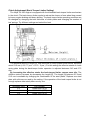
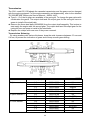
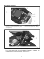
Front/Rear Speed Sensor
The sensors attached on the side of the front/rear wheel are related to the control
functions such as the traction control (S-KTRC) and pit lane speed limit, so they are
removable in both the ABS (KIBS) equipped or non-equipped motorcycles.
Refer to the dimensions illustrated below to change the components around the front/rear
wheels.
Even if a replacement is installed properly, the speed sensor may malfunction due to
noise etc.
Ask a tuning shop to make parts.
Front Speed Sensor
Sensor detecting point :φ138.8 ∼ 139.2 from the center of the axle
The number of the rotor teeth for speed detection : 48
The distance from the sensor end to the rotor : 0.4 ∼ 1.6 mm (0.02 ∼ 0.06 in.)
Sensor installation angle : 90°(See the illustration below.)
49
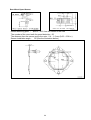
Rear Wheel Speed Sensor
Sensor detecting point : φ89.8 ∼ 90.2 from the center of the axle
The number of the rotor teeth for speed detection : 50
The distance from the sensor end to the rotor : 0.4 ∼ 1.6 mm (0.02 ∼ 0.06 in.)
Sensor installation angle : 90°(See the illustration below.)
50
Front/Rear Speed Detection Rotor
The standard rotor is recommended for the front/rear speed detection.
NOTE
○ Because the front/rear wheel speed sensors are magnetic type, use magnetic iron
material and conform the number and shape of the teeth to those of the standard rotor.
Front Wheel Rotor: 21007-0166
Rear Wheel Rotor: 21007-0167
51
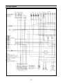
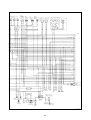
Wiring Diagram
52
53
Dummy page
54
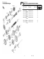
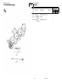
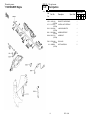
Racing Kit Parts List
This catalog covers:
’11 ZX1000JBFR Engine
GRID NO.
B-3
This grid covers:
Oil Catch Tank
Quantity-ZX1000
Ref.
No.
Part No.
Description
Spec Code
’11
JBFR
11056
11056-1232
(OPTION)
11056A 11056-1233
(OPTION)
52001 52001-0553
(OPTION)
92022 92022-304
(OPTION)
92027 92027-194
(OPTION)
BRACKET,OIL TANK,UPP
1
BRACKET,OIL TANK,LWR
1
TANK-OIL
1
WASHER,6.2X11X1
1
COLLAR,L=11.1
2
92075
DAMPER
2
CLAMP
4
TUBE,TANK-A/C
1
TUBE,CASE-TANK
1
BOLT-FLANGED,6X20
4
BOLT-FLANGED,6X10
1
92075-277
(OPTION)
92171 92171-0338
(OPTION)
92192 92192-1025
(OPTION)
92192A 92192-1026
(OPTION)
130 130BA0620
(OPTION)
130A 130BD0610
(OPTION)
1
DEC. 1,2010
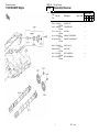
This catalog covers:
’11 ZX1000JBFR Engine
GRID NO.
B-4
This grid covers:
Camshaft(s)/Tensioner
Quantity-ZX1000
Ref.
No.
Part No.
Description
Spec Code
’11
JBFR
12046
12046-0034
(OPTION)
12048 12048-0082
(OPTION)
13116 13116-1166
(OPTION)
49118 49118-0728
(OPTION)
49118A 49118-0729
(OPTION)
SPROCKET,32T
2
TENSIONER-ASSY
1
ROD-PUSH
1
CAMSHAFT-COMP,INTAKE
1
CAMSHAFT-COMP,EXHAUST
1
92055
RING-O,20.8X1.9
1
RING-O,5MM
1
BOLT,FLANGED,6X8
4
NUT,FLANGED,6MM
1
92055-0053
(OPTION)
92055A 92055-011
(OPTION)
92153 92153-0455
(OPTION)
92210 92210-0630
(OPTION)
2
DEC. 1,2010
This catalog covers:
’11 ZX1000JBFR Engine
GRID NO.
B-5
This grid covers:
Crankshaft/Piston(s)
Quantity-ZX1000
Ref.
No.
Part No.
Description
Spec Code
’11
JBFR
92139
92139A
92139B
92139C
92139D
92139-0746
(OPTION)
92139-0747
(OPTION)
92139-0748
(OPTION)
92139-0749
(OPTION)
92139-0750
(OPTION)
BUSHING,#1,BLUE
BUSHING,#1,BLACK
6
BUSHING,#1,BROWN
AR
BUSHING,#1,PINK
AR
BUSHING,#2,BLUE
AR
92139E 92139-0751
(OPTION)
92139F 92139-0752
(OPTION)
92139G 92139-0753
(OPTION)
92139H 92139-0754
(OPTION)
92139I 92139-0755
(OPTION)
BUSHING,#2,BLACK
92139J 92139-0756
(OPTION)
92139K 92139-0757
(OPTION)
BUSHING,CONROD,BROWN
3
AR
4
BUSHING,#2,BROWN
AR
BUSHING,#2,PINK
AR
BUSHING,CONROD,BLUE
AR
BUSHING,CONROD,BLACK
AR
BUSHING,CONROD,PINK
DEC. 1,2010
8
AR
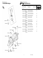
This catalog covers:
’11 ZX1000JBFR Engine
GRID NO.
B-6
This grid covers:
Clutch
Quantity-ZX1000
Ref.
No.
Part No.
Description
Spec Code
’11
JBFR
13089
13089-0003
(OPTION)
13089A 13089-0011
(OPTION)
13089B 13089-0012
(OPTION)
13091 13091-1041
(OPTION)
39108 39108-0005
(OPTION)
92022
92022-304
(OPTION)
4
PLATE-CLUTCH,STD
1
PLATE-CLUTCH,STD +40%
1
PLATE-CLUTCH,STD +60%
1
HOLDER,CLUTCH SPRING
6
RETAINER-SPRING,STD+1MM
6
WASHER,6.2X11X1
6
DEC. 1,2010
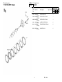
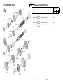
This catalog covers:
’11 ZX1000JBFR Engine
GRID NO.
B-7
This grid covers:
Transmission(1/2)(TYPE-A)
Quantity-ZX1000
Ref.
No.
Part No.
Description
Spec Code
’11
JBFR
13127
13127-0638
(OPTION)
13128 13128-0671
(OPTION)
13144 13144-0021
(OPTION)
13144A 13144-0022
(OPTION)
13262 13262-0618
(OPTION)
SHAFT-TRANSMISSION INPUT,15T
1
SHAFT-TRANSMISSION OUTPUT
1
SPROCKET-OUTPUT,16T,#520
1
SPROCKET-OUTPUT,17T,#520
1
GEAR,OUTPUT 3RD,33T
1
13262A 13262-0622
(OPTION)
13262B 13262-0645
(OPTION)
13262C 13262-0648
(OPTION)
13262D 13262-0664
(OPTION)
13262E 13262-0856
(OPTION)
GEAR,INPUT 6TH,23T
1
GEAR,OUTPUT 4TH,32T
1
GEAR,INPUT 5TH,21T
1
GEAR,OUTPUT LOW,38T
1
GEAR,INPUT 2ND,19T
1
13262F 13262-0880
(OPTION)
13262G 13262-0901
(OPTION)
13262H 13262-0905
(OPTION)
92152 92152-1522
(OPTION)
92200 92200-0051
(OPTION)
GEAR,OUTPUT 2ND,39T
1
GEAR,OUTPUT 5TH,29T
1
GEAR,OUTPUT 6TH,30T
1
COLLAR,SPROCKET
1
WASHER,28.1X34.0X1.2
AR
92200A 92200-0225
(OPTION)
92200B 92200-0226
(OPTION)
92200C 92200-0227
(OPTION)
92200D 92200-0228
(OPTION)
92200E 92200-0229
(OPTION)
WASHER,28.1X34.0X0.8
AR
WASHER,28.1X34.0X1.0
AR
WASHER,28.1X34.0X1.4
AR
WASHER,28.1X34.0X1.6
AR
WASHER,28.3X34.0X1.2
AR
92200F 92200-0230
(OPTION)
WASHER,28.3X34.0X1.4
AR
5
DEC. 1,2010
This catalog covers:
’11 ZX1000JBFR Engine
GRID NO.
B-8
This grid covers:
Transmission(2/2)(TYPE-A)
Quantity-ZX1000
Ref.
No.
Part No.
Description
Spec Code
’11
JBFR
92200G 92200-0231
(OPTION)
92200H 92200-0232
(OPTION)
92200I 92200-0748
(OPTION)
92200J 92200-0749
(OPTION)
92200K 92200-0750
(OPTION)
6
WASHER,28.3X34.0X1.8
AR
WASHER,28.3X34.0X2.0
AR
WASHER,28.3X34.0X2.6
AR
WASHER,28.3X34.0X2.8
AR
WASHER,28.3X34.0X3.0
AR
DEC. 1,2010
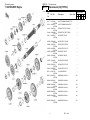
This catalog covers:
’11 ZX1000JBFR Engine
GRID NO.
B-9
This grid covers:
Transmission(1/2)(TYPE-B)
Quantity-ZX1000
Ref.
No.
Part No.
Description
Spec Code
’11
JBFR
13127
13127-0639
(OPTION)
13128 13128-0671
(OPTION)
13144 13144-0021
(OPTION)
13144A 13144-0022
(OPTION)
13262 13262-0619
(OPTION)
SHAFT-TRANSMISSION INPUT,13T
1
SHAFT-TRANSMISSION OUTPUT
1
SPROCKET-OUTPUT,16T,#520
1
SPROCKET-OUTPUT,17T,#520
1
GEAR,OUTPUT 4TH,31T
1
13262A 13262-0624
(OPTION)
13262B 13262-0642
(OPTION)
13262C 13262-0652
(OPTION)
13262D 13262-0881
(OPTION)
13262E 13262-0895
(OPTION)
GEAR,OUTPUT LOW,31T
1
GEAR,OUTPUT 3RD,34T
1
GEAR,INPUT 6TH,21T
1
GEAR,INPUT 5TH,18T
1
GEAR,INPUT 2ND,19T
1
13262F 13262-0898
(OPTION)
13262G 13262-0902
(OPTION)
13262H 13262-0906
(OPTION)
92152 92152-1522
(OPTION)
92200 92200-0051
(OPTION)
GEAR,OUTPUT 2ND,37T
1
GEAR,OUTPUT 5TH,26T
1
GEAR,OUTPUT 6TH,29T
1
COLLAR,SPROCKET
1
WASHER,28.1X34.0X1.2
AR
92200A 92200-0225
(OPTION)
92200B 92200-0226
(OPTION)
92200C 92200-0227
(OPTION)
92200D 92200-0228
(OPTION)
92200E 92200-0229
(OPTION)
WASHER,28.1X34.0X0.8
AR
WASHER,28.1X34.0X1.0
AR
WASHER,28.1X34.0X1.4
AR
WASHER,28.1X34.0X1.6
AR
WASHER,28.3X34.0X1.2
AR
92200F 92200-0230
(OPTION)
WASHER,28.3X34.0X1.4
AR
7
DEC. 1,2010
This catalog covers:
’11 ZX1000JBFR Engine
GRID NO.
B-10
This grid covers:
Transmission(2/2)(TYPE-B)
Quantity-ZX1000
Ref.
No.
Part No.
Description
Spec Code
’11
JBFR
92200G 92200-0231
(OPTION)
92200H 92200-0232
(OPTION)
92200I 92200-0748
(OPTION)
92200J 92200-0749
(OPTION)
92200K 92200-0750
(OPTION)
8
WASHER,28.3X34.0X1.8
AR
WASHER,28.3X34.0X2.0
AR
WASHER,28.3X34.0X2.6
AR
WASHER,28.3X34.0X2.8
AR
WASHER,28.3X34.0X3.0
AR
DEC. 1,2010
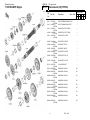
This catalog covers:
’11 ZX1000JBFR Engine
GRID NO.
B-11
This grid covers:
Transmission(1/2)(TYPE-C)
Quantity-ZX1000
Ref.
No.
Part No.
Description
Spec Code
’11
JBFR
13127
13127-0640
(OPTION)
13128 13128-0671
(OPTION)
13144 13144-0021
(OPTION)
13144A 13144-0022
(OPTION)
13262 13262-0620
(OPTION)
SHAFT-TRANSMISSION INPUT,14T
1
SHAFT-TRANSMISSION OUTPUT
1
SPROCKET-OUTPUT,16T,#520
1
SPROCKET-OUTPUT,17T,#520
1
GEAR,INPUT 5TH,20T
1
13262A 13262-0625
(OPTION)
13262B 13262-0643
(OPTION)
13262C 13262-0646
(OPTION)
13262D 13262-0869
(OPTION)
13262E 13262-0896
(OPTION)
GEAR,OUTPUT LOW,34T
1
GEAR,OUTPUT 3RD,28T
1
GEAR,OUTPUT 4TH,33T
1
GEAR,INPUT TOP,23T
1
GEAR,INPUT 2ND,18T
1
13262F 13262-0899
(OPTION)
13262G 13262-0903
(OPTION)
13262H 13262-0907
(OPTION)
92152 92152-1522
(OPTION)
92200 92200-0051
(OPTION)
GEAR,OUTPUT 2ND,38T
1
GEAR,OUTPUT 5TH,28T
1
GEAR,OUTPUT 6TH,31T
1
COLLAR,SPROCKET
1
WASHER,28.1X34.0X1.2
AR
92200A 92200-0225
(OPTION)
92200B 92200-0226
(OPTION)
92200C 92200-0227
(OPTION)
92200D 92200-0228
(OPTION)
92200E 92200-0229
(OPTION)
WASHER,28.1X34.0X0.8
AR
WASHER,28.1X34.0X1.0
AR
WASHER,28.1X34.0X1.4
AR
WASHER,28.1X34.0X1.6
AR
WASHER,28.3X34.0X1.2
AR
92200F 92200-0230
(OPTION)
WASHER,28.3X34.0X1.4
AR
9
DEC. 1,2010
This catalog covers:
’11 ZX1000JBFR Engine
GRID NO.
B-12
This grid covers:
Transmission(2/2)(TYPE-C)
Quantity-ZX1000
Ref.
No.
Part No.
Description
Spec Code
’11
JBFR
92200G 92200-0231
(OPTION)
92200H 92200-0232
(OPTION)
92200I 92200-0748
(OPTION)
92200J 92200-0749
(OPTION)
92200K 92200-0750
(OPTION)
10
WASHER,28.3X34.0X1.8
AR
WASHER,28.3X34.0X2.0
AR
WASHER,28.3X34.0X2.6
AR
WASHER,28.3X34.0X2.8
AR
WASHER,28.3X34.0X3.0
AR
DEC. 1,2010
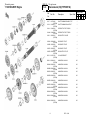
This catalog covers:
’11 ZX1000JBFR Engine
GRID NO.
B-13
This grid covers:
Transmission(1/2)(TYPE-D)
Quantity-ZX1000
Ref.
No.
Part No.
Description
Spec Code
’11
JBFR
13127
13127-0641
(OPTION)
13128 13128-0671
(OPTION)
13144 13144-0021
(OPTION)
13144A 13144-0022
(OPTION)
13262 13262-0626
(OPTION)
SHAFT-TRANSMISSION INPUT,16T
1
SHAFT-TRANSMISSION OUTPUT
1
SPROCKET-OUTPUT,16T,#520
1
SPROCKET-OUTPUT,17T,#520
1
GEAR,OUTPUT LOW,37T
1
13262A 13262-0644
(OPTION)
13262B 13262-0654
(OPTION)
13262C 13262-0897
(OPTION)
13262D 13262-0900
(OPTION)
13262E 13262-0904
(OPTION)
GEAR,OUTPUT 3RD,36T
1
GEAR,INPUT 6TH,22T
1
GEAR,INPUT 2ND,18T
1
GEAR,OUTPUT 2ND,36T
1
GEAR,OUTPUT 5TH,30T
1
13262F 13262-0908
(OPTION)
92152 92152-1522
(OPTION)
92200 92200-0051
(OPTION)
92200A 92200-0225
(OPTION)
92200B 92200-0226
(OPTION)
GEAR,OUTPUT 6TH,28T
1
COLLAR,SPROCKET
1
WASHER,28.1X34.0X1.2
AR
WASHER,28.1X34.0X0.8
AR
WASHER,28.1X34.0X1.0
AR
92200C 92200-0227
(OPTION)
92200D 92200-0228
(OPTION)
92200E 92200-0229
(OPTION)
92200F 92200-0230
(OPTION)
92200G 92200-0231
(OPTION)
WASHER,28.1X34.0X1.4
AR
WASHER,28.1X34.0X1.6
AR
WASHER,28.3X34.0X1.2
AR
WASHER,28.3X34.0X1.4
AR
WASHER,28.3X34.0X1.8
AR
92200H 92200-0232
(OPTION)
WASHER,28.3X34.0X2.0
AR
11
DEC. 1,2010
This catalog covers:
’11 ZX1000JBFR Engine
GRID NO.
B-14
This grid covers:
Transmission(2/2)(TYPE-D)
Quantity-ZX1000
Ref.
No.
Part No.
Description
Spec Code
’11
JBFR
92200I
92200-0748
(OPTION)
92200J 92200-0749
(OPTION)
92200K 92200-0750
(OPTION)
12
WASHER,28.3X34.0X2.6
AR
WASHER,28.3X34.0X2.8
AR
WASHER,28.3X34.0X3.0
AR
DEC. 1,2010
This catalog covers:
’11 ZX1000JBFR Engine
GRID NO.
C-3
This grid covers:
Transmission(1/2)(TYPE-E/F/G)
Quantity-ZX1000
Ref.
No.
Part No.
Description
Spec Code
’11
JBFR
13127
13127-0642
(OPTION)
13128 13128-0671
(OPTION)
13144 13144-0021
(OPTION)
13144A 13144-0022
(OPTION)
13262 13262-0615
(OPTION)
SHAFT-TRANSMISSION INPUT,15T
1
SHAFT-TRANSMISSION OUTPUT
1
SPROCKET-OUTPUT,16T,#520
1
SPROCKET-OUTPUT,17T,#520
1
GEAR,OUTPUT LOW,39T
1
13262A 13262-0655
(OPTION)
13262B 13262-0656
(OPTION)
13262C 13262-0657
(OPTION)
13262D 13262-0909
(OPTION)
92152 92152-1522
(OPTION)
GEAR,INPUT 6TH,21T
1
GEAR,INPUT 6TH,24T
1
GEAR,INPUT 6TH,22T
1
GEAR,OUTPUT 6TH,26T
1
COLLAR,SPROCKET
1
92200
92200-0051
(OPTION)
92200-0225
(OPTION)
92200-0226
(OPTION)
92200-0227
(OPTION)
92200-0228
(OPTION)
WASHER,28.1X34.0X1.2
AR
WASHER,28.1X34.0X0.8
AR
WASHER,28.1X34.0X1.0
AR
WASHER,28.1X34.0X1.4
AR
WASHER,28.1X34.0X1.6
AR
92200E 92200-0229
(OPTION)
92200F 92200-0230
(OPTION)
92200G 92200-0231
(OPTION)
92200H 92200-0232
(OPTION)
92200I 92200-0748
(OPTION)
WASHER,28.3X34.0X1.2
AR
WASHER,28.3X34.0X1.4
AR
WASHER,28.3X34.0X1.8
AR
WASHER,28.3X34.0X2.0
AR
WASHER,28.3X34.0X2.6
AR
92200J 92200-0749
(OPTION)
WASHER,28.3X34.0X2.8
AR
92200A
92200B
92200C
92200D
13
DEC. 1,2010
This catalog covers:
’11 ZX1000JBFR Engine
GRID NO.
C-4
This grid covers:
Transmission(2/2)(TYPE-E/F/G)
Quantity-ZX1000
Ref.
No.
Part No.
Description
Spec Code
’11
JBFR
92200K 92200-0750
(OPTION)
14
WASHER,28.3X34.0X3.0
DEC. 1,2010
AR
This catalog covers:
’11 ZX1000JBFR Engine
GRID NO.
C-5
This grid covers:
Transmission(1/2)(INPUT3RD/4TH GEAR)
Quantity-ZX1000
Ref.
No.
Part No.
Description
Spec Code
’11
JBFR
13128
13128-0671
(OPTION)
13140 13140-0625
(OPTION)
13144 13144-0021
(OPTION)
13144A 13144-0022
(OPTION)
13262 13262-0630
(OPTION)
SHAFT-TRANSMISSION OUTPUT
1
FORK-SHIFT
1
SPROCKET-OUTPUT,16T,#520
1
SPROCKET-OUTPUT,17T,#520
1
GEAR,INPUT 3RD&4TH,19T&21T,A/A
1
13262A 13262-0632
(OPTION)
13262B 13262-0633
(OPTION)
13262C 13262-0634
(OPTION)
13262D 13262-0637
(OPTION)
13262E 13262-0638
(OPTION)
GEAR,INPUT 3RD&4TH,19T&20T,B/B
1
GEAR,INPUT 3RD&4TH,19T&21T,B/A
1
GEAR,INPUT 3RD&4TH,19T&21T,B/C
1
GEAR,INPUT 3RD&4TH,16T&20T,C/B
1
GEAR,INPUT 3RD&4TH,16T&21T,C/A
1
13262F 13262-0639
(OPTION)
13262G 13262-0640
(OPTION)
13262H 13262-0641
(OPTION)
13262I 13262-0665
(OPTION)
13262J 13262-0891
(OPTION)
GEAR,INPUT 3RD&4TH,16T&21T,C/C
1
GEAR,INPUT 3RD&4TH,21T&20T,D/B
1
GEAR,INPUT 3RD&4TH,21T&21T,D/A
1
GEAR,INPUT 3RD&4TH,19T&20T
1
GEAR,INPUT 3RD&4TH,19T&21T
1
92152
92152-1522
(OPTION)
92200 92200-0051
(OPTION)
92200A 92200-0225
(OPTION)
92200B 92200-0226
(OPTION)
92200C 92200-0227
(OPTION)
COLLAR,SPROCKET
1
92200D 92200-0228
(OPTION)
15
WASHER,28.1X34.0X1.2
AR
WASHER,28.1X34.0X0.8
AR
WASHER,28.1X34.0X1.0
AR
WASHER,28.1X34.0X1.4
AR
WASHER,28.1X34.0X1.6
AR
DEC. 1,2010
This catalog covers:
’11 ZX1000JBFR Engine
GRID NO.
C-6
This grid covers:
Transmission(2/2)(INPUT3RD/4TH GEAR)
Quantity-ZX1000
Ref.
No.
Part No.
Description
Spec Code
’11
JBFR
92200E 92200-0229
(OPTION)
92200F 92200-0230
(OPTION)
92200G 92200-0231
(OPTION)
92200H 92200-0232
(OPTION)
92200I 92200-0748
(OPTION)
WASHER,28.3X34.0X1.2
AR
WASHER,28.3X34.0X1.4
AR
WASHER,28.3X34.0X1.8
AR
WASHER,28.3X34.0X2.0
AR
WASHER,28.3X34.0X2.6
AR
92200J 92200-0749
(OPTION)
92200K 92200-0750
(OPTION)
WASHER,28.3X34.0X2.8
AR
WASHER,28.3X34.0X3.0
AR
16
DEC. 1,2010
This catalog covers:
’11 ZX1000JBFR Engine
GRID NO.
C-7
This grid covers:
Engine Cover(s)
Quantity-ZX1000
Ref.
No.
Part No.
Description
Spec Code
’11
JBFR
11004
11004-0719
(OPTION)
11004A 11004-0720
(OPTION)
11004B 11004-0721
(OPTION)
11004C 11004-0722
(OPTION)
11061 11061-0754
(OPTION)
GASKET-HEAD,T=0.65
1
GASKET-HEAD,T=0.60
1
GASKET-HEAD,T=0.55
1
GASKET-HEAD,T=0.50
1
GASKET,CLUTCH COVER
1
11061A 11061-0755
(OPTION)
11061B 11061-0756
(OPTION)
11061C 11061-0757
(OPTION)
11061D 11061-0758
(OPTION)
92066 92066-1005
(OPTION)
GASKET,GENERATOR COVER
1
GASKET,PULSER COVER
1
GASKET,OIL PAN
1
GASKET,STARTER COVER
1
PLUG
4
17
DEC. 1,2010
This catalog covers:
’11 ZX1000JBFR Engine
GRID NO.
C-8
This grid covers:
Throttle
Quantity-ZX1000
Ref.
No.
Part No.
Description
Spec Code
’11
JBFR
16021
16021-0055
(OPTION)
92172 92172-0745
(OPTION)
92172A 92172-0746
(OPTION)
18
SCREW-THROTTLE STOP
1
SCREW
1
SCREW,REMOTE TYPE
1
DEC. 1,2010
This catalog covers:
’11 ZX1000JBFR Engine
GRID NO.
C-9
This grid covers:
Fuel Injection
Quantity-ZX1000
Ref.
No.
Part No.
Description
Spec Code
’11
JBFR
11056
11056-1243
(OPTION)
21175 21175-0756
(OPTION)
23016 23016-0006
(OPTION)
26031 26031-0999
(OPTION)
26031A 26031-1219
(OPTION)
BRACKET,TIP OVER SENSOR
1
CONTROL UNIT-ELECTRONIC
1
LAMP-ASSY,INDICATOR
1
HARNESS,INTERFACE
1
HARNESS,KIT
1
27002
RELAY-ASSY
1
BOLT-FLANGED,6X16
2
27002-1062
(OPTION)
130BA0616
(OPTION)
130
19
DEC. 1,2010
This catalog covers:
’11 ZX1000JBFR Chassis
GRID NO.
D-3
This grid covers:
Frame Fittings
Quantity-ZX1000
Ref.
No.
Part No.
Description
Spec Code
’11
JBFR
31064
31064-0187
(OPTION)
32099 32099-0046
(OPTION)
32099A 32099-0047
(OPTION)
54012 54012-0570
(OPTION)
59101 59101-0008
(OPTION)
PIPE-COMP,GRIP
1
CASE,UPP
1
CASE,LWR
1
CABLE-THROTTLE,HI
2
REEL,R19.7,65DEG
1
59101A 59101-0009
(OPTION)
92026 92026-0724
(OPTION)
92152 92152-0798
(OPTION)
120 120CA0518
(OPTION)
132 132BA0830
(OPTION)
REEL,R21.4,60DEG
1
SPACER,REAR HEIGHT ADJ.,SET
1
COLLAR,8X16X3.5
1
BOLT-SOCKET,5X18
2
BOLT-FLANGED-SMALL,8X30
2
O RING,12MM
1
670
670B2012
(OPTION)
20
DEC. 1,2010
This catalog covers:
’11 ZX1000JBFR Chassis
GRID NO.
This grid covers:
D-4
Front Fork
Quantity-ZX1000
Ref.
No.
Part No.
Description
Spec Code
’11
JBFR
43082
43082-0088
(OPTION)
44026 44026-0163
(OPTION)
44026A 44026-0164
(OPTION)
55020 55020-0795
(OPTION)
130 130BA0820
(OPTION)
21
PAD-ASSY-BRAKE,FR,F9633
2
SPRING-FRONT FORK,K=9.75N/MM
2
SPRING-FRONT FORK,K=10.75N/MM
2
GUARD,CHAIN
1
BOLT-FLANGED,8X20
1
DEC. 1,2010
Doc No. 99929-0547-01