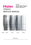
1
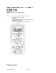
SERVICE MANUAL
Order No. Ref0912S021V0
Refrigerator
MODEL: CFE633CWE
CFE633CSE
WARNING
This service information is designed for experienced repair technicians only and is not designed for use by the general public. It
dose not contain warnings and cautions to advice non-technical individuals of potential dangers in attempting to service a product.
Product powered by electricity should by serviced or repaired only by experienced professional technicians. Any attempt to service
or repair the product or products dealt with in this service information by anyone else could result in serious injury or death.
◎2009(HAIER ELECTRICAL APPLIANCES COR. LTD)
All right reserved. Unauthorized copying and distribution is a violation of law。
SERVICE MANUAL
Model: CFE629CW
Issue
2009-12-23
Rev.
Ref0912S021V0
Contents
Table of Contents ·········································································································· 1
1. General Information ·································································································· 2
1-1. General guideline ······························································································· 2
1-2. Insurance test ····································································································· 3
1-3. How to read this Service Manual········································································ 5
2. Product Feature ········································································································ 6
2-1. Specifications ····································································································· 6
2-2. Main Functions and Features ············································································· 9
2-3. External views ···································································································· 9
2-3. Two-Door Refrigerator Structure ································································· 9
2-4. Product Dimensions ·················································································· 9
3. Disassembly ············································································································ 10
3-1. Installing the Freezer Drawer Handle ······························································· 10
3-2. Installing and Removing Door ·········································································· 10
3-2-1. Dismantle and install the front decoration ·············································· 11
3-2-2. Dismantles and install the upper decoration strip and cables ················ 11
3-2-3. Dismantle and install the middle and lower hinge ·································· 12
3-5. Removing the Air-Duct ······················································································· 13
3-5-1. Removal of fridge air-duct·········································································· 13
3-5-2. Removal of freezing air-duct ······································································ 13
4. Control and display system ····················································································· 14
4-1. Control and display panel ··················································································· 14
4-1-1. Models: CFE633*······················································································· 14
4-2. Error code display and sensor positions ·····························································16
4-2-1. Sensor location description········································································ 15
4-2-2. Graphic display of the sensor location ······················································· 16
4-3. Self test model···································································································· 17
5. Control principle of electronic component ···························································· 17
2
SERVICE MANUAL
Model: CFE629CW
Issue
2009-12-23
Rev.
Ref0912S021V0
5-1. Air Escaper ········································································································· 17
5-2. Control Principle of the Fan motor······································································ 17
5-3. Defrost control principle······················································································ 17
6. System flow principle ······························································································· 18
6-1. Refrigeration flow chart ····················································································· 18
6-2. Perspective of the Refrigeration System ·························································· 19
6-3. Air flow scenograph ·························································································· 20
7. Circuit diagram·········································································································· 21
7-1. Main Control PCB diagram ··············································································· 21
7-2. Main Control PCB connections ········································································· 22
8. Trouble shooting······································································································· 23
8-1. Common problems and solutions ····································································· 23
8-1-1. food in the fridge storage compartment is frozen ····································· 23
8-1-2. the buzzer beeps to alarm ········································································ 23
8-1-3. No defrosting ···························································································· 23
8-1-4. Neither displaying nor starting when powering on ··································· 24
8-1-5. Poor freezing effect accompanied by loud noise ····································· 24
8-2. Examination and Solutions for Other Problems ·············································· 25
8-3. Checking flow chart ·························································································· 27
3
SERVICE MANUAL
Model: CFE629CW
Issue
2009-12-23
Rev.
Ref0912S021V0
Chapter 1 General Information
1-1. General Guidelines
When servicing, observe the original lead dress. If a short circuit is found, replace all parts which
have been overheated or damaged by the short circuit. After servicing, see to it that all the protective
devices such as insulation barriers, insulation papers shields are properly installed. After servicing,
make the following leakage current checks to prevent the customer from being exposed to shock
hazards.
1) Leakage Current Cold Check
2) Leakage Current Hot Check
3) Prevention of Electro Static Discharge (ESD) to Electrostatic Sensitive
1-2. Insurance test
1. Check if there is any leak of current.
2. Cut out the power supply before the repair to avoid an electrical shock hazard.
3. In the case of a live-line test, insulating gloves should be worn to avoid potential electrical shock.
4. Confirm the rated current, voltage and capacity before testing with any kinds of instruments.
5. Watch if the upper door is open when you check something at a lower position.
6. Take out every part in the cabinet before moving the machine, especially things like panels (e.g. glass
shelf).
7. Please wear intact cotton gloves when repair any parts of the evaporator, so that scratches by the
sharp fins can be avoided.
8. If there is a breakdown with the refrigeration system, please surrender the machine to the service
center, else the leaked refrigerant may pollute the atmosphere.
9. The refrigerator use AC of 220V with a frequency of 50Hz.
10. A big fluctuation of voltage (exceed the range 187~230V) may cause a start failure of the refrigerator,
a burn-out of the control panel and compressor, or an abnormal sound from the compressor in
operation. In this condition an automatic voltage regulator over 60W should be added.
11. Take care not to damage the supply line. Don’t yank at the line; pull the plug out gently from the
receptacle. Don’t press the line under the cabinet or step on it. Take care not to roll on or damage the
supply line when moves the machine from the wall.
12. In the case of leakage of inflammable gases like carbon monoxide, open the door and windows. Don’t
pull out or insert the plugs of the appliance.
13. Don’t touch the refrigeration surface of the freezing compartment when the refrigerator is in operation,
especially when your hand is wet, else you may be glued to the surface.
14. Pull out the plug of power supply during clearance or power outage. Wait at least five minutes to
resume the power supply in order to prevent damage to the compressor caused by continuous restart.
4
SERVICE MANUAL
Model: CFE629CW
Issue
2009-12-23
Rev.
Ref0912S021V0
Photo used in this manual
The illustration and photos used in this Manual may not base on the final design of products, which
may differ from your products in some way.
1-3. How to read this Service Manual
1-3-1. Using Icons
The meaning of each icon is described in the table below:
Note:
A “note” provides information that is not indispensable, but may nevertheless be valuable to the
reader, such as tips and tricks.
Caution:
A “caution” is used when there is danger, through incorrect manipulation, may damage equipment,
loose data, get an unexpected result or has to restart (part of) a procedure.
Warning:
A “warning” is used when there is danger of personal injury.
Reference:
A “reference” guides to other places in this binder or in this manual, where we will find additional
information on a specific topic.
5
SERVICE MANUAL
Model: CFE629CW
Issue
2009-12-23
Rev.
Ref0912S021V0
Chapter 2 Product Feature
6
2-1. SPECIFICATIONS
1
Models
CFE 633 CW
CFE633CSE
Sketch
Product description
Refrigerator
(Refrigerator/Freezer)
Type of appliance (FS= freestanding/BI= built-in)
FS
Type of cooling system(NF=no frost/ S=static)
NF
SN/ST
Climate class*
4*
Freezer compartment / Star rating
2
Key features
Gross capacity
L
322
Total net capacity
L
290
Net capacity refrigerator compartment
L
210
Net capacity freezer compartment /ice compartment
L
80/80
Freezing capacity
kg
11kg
Energy consumption / year
kWh
310
Max storage time at breakdown Freezer
Min
16
Defrosting
(M=manual
Frost free system
yes
Defrost water outlet
yes
Air circulating ventilator
yes
Kind of coolant
3
A
A=automatic)
R600a/ 52g
(R134a/R600a)
Technical data
Voltage / frequency
V/Hz
220-240~/ 50
Input power / mains fuse minimum
W /A
100/ (DC)
Temperature range (from>to)
Refrigerator
Chiller / Meat Crisper
Vegetable Crisper
Freezer
°C
1-8°C
- / 3-10°C
0-10°C
-16 ~-25°C
SERVICE MANUAL
Model: CFE629CW
Issue
2009-12-23
Rev.
Ref0912S021V0
Features:
Energy consumption per l 100 net / year
kWh
0.260
Energy consumption per l 100 net / 24h
kWh
0.85
K
Cooling system: K=Compressor / A=Absorption
dB(A)
Max noise level
7
42
4 Aesthetics
W
Colors: W=white G=silver gray
G
B=Obsidian SS=stainless steel
Fascia panel / Handle
w/w
(w / c)
F= flat / R= rounded / S= streamline
R
Inside colour
w
Compartments
number
Bottle compartment
Hinged
n°
2
n°
4
(r =right l =left) / reversible
r/X
Fridge / Freezer
3/-
Shelves:
Number
Type
Color
g/-
(gr=grill / g=glass / p=plastic)
t
w-white / b=blue / t=transparent.
Adjustable
N
(Y=yes / N=not)
Foldable Shelf
No
Bottle Rack
No
Drawers:
Plastic drawers (fully freezing comp.)
n°.
2
Half freezing comp
n°.
1
t
Colour of drawer (w=white/t=transp./g=green)
Crisper:
Chiller (t)
Chiller / Meat (salad crisper) transparent / white
Vegetable crisper(s)
5
t
transparent / white
Equipment & accessories
Control panel
Interior
Interior / exterior
Thermometer
Interior
interior / exterior
No
Display type
Control lamps
No
green / yellow /white
Over temperature alarm
LED / acoustic
acoustic
Adjustable thermostat
yes
Fast freeze switch /-function
yes
No
Deodorizing
Interior light
W
x
LED light
n°
Half
Freeze pack(s)
n°
3
ice maker Manual/ Automatic
M
SERVICE MANUAL
Model: CFE629CW
n°
Ice cube tray(s)
Adjustable feet
front / rear
Length of cable/incl. plug
Condenser
2/-
cm
200
B
cm
188/59.5/67
Depth Without handle
cm
67
Depth with open door
cm
1188
Door open angle
n°
<135
Net weight
kg
76
cm
184.2/65.7/71.7
Gross weight
kg
80
40 ' Container load
pcs
54
40 ' HC Container load
pcs
72
RS
RS
( H / W / D)
Packing dimensions & load ability
(H / W / D)
Recycling symbols
Packing materials / Recycling symbols (RS)
9
1
dimensions
Packing dimensions
8
Ref0912S021V0
n°
Back wall / Integrated
Unit dimensions
7
Rev.
2
Egg trays
Product
2009-12-23
yes
Butter holder
6
Issue
6270
Carton
weight in gr
Polystyrene
weight in gr
06
2570
Polyethylene foil
weight in gr
04
210
Service
Users instruction
(languages)
D / F / I / GB / E / P / NL
2-2 Main Functions and Features
◆
Energy saving and convenience (only in some models).
◆
Half-shelf structure.
◆
Innovative long-efficiency lighting system.
◆
Foldaway wine holder.
◆
Large crisper with humidity adjustment.
◆
Holiday function.
◆
Power ON/OFF function is set on the display panel (only in some models).
◆
Fridge storage compartment can be set on/off separately.
◆
Intelligent alarm function: automatic alarm at over temperature, malfunction, door open.
◆
Touch keys (only in some models).
◆
Deodorizer (only in some models).
◆
Zero degree fresh keeping.
8
SERVICE MANUAL
Model: CFE629CW
Issue
2009-12-23
Rev.
Ref0912S021V0
2-3. External views
9
Two-Door Refrigerator Structure
Display panel
Shelf
Turnover box
Turnover box rack
Small bottle rack
Wire wine holder
Fresh keeping box cover
Fresh keeping box
Crisper cover
Crisper
Large bottle rack
Small bottle rack
Freezer storage
compartment drawer
2-4. Product Dimensions
Two-Door Refrigerator Dimensions:
Refrigerator height H=1880mm
Refrigerator width W=595mm
Refrigerator depth D=670mm
Cabinet depth D1=576mm
Door depth D2=78mm
SERVICE MANUAL
Model: CFE629CW
Issue
2009-12-23
Rev.
Ref0912S021V0
Chapter 3 Disassembly
3-1
10
Installing and Removing Door
Precautions During Dismantling and Installation of The Door
(1) Before removing the doors, please remove food from the shelves and the bottle guards. Then,
unplug the refrigerator power cord to avoid personal injury, product damage or property loss.
(2) During dismantling of the door, in order to avoid possible personal injury, product damage or
property loss, at least two adults are needed to perform the following operations.
(3) While lifting the hinges to separate it from the door, please take care to prevent the door from falling
forward.
3-2-1 Dismantle and install front decoration strip of the table-board and the upper hinge
PART-1
After change
Before change
Front decoration strip of the table-board
Screw
Upper hinge
Cover 2
Cover 1
Screw
⑴ Pull decoration covers 1 and 2 downward to remove them and retain.
⑵ Detach the 2 screws fixing the front decoration strip of the table-board.
⑶ Lift the front decoration strip of the table-board outward and upward. At this time, there are wires
connecting it. Please do not disconnect the wires. Gently put the front decoration strip on the top
of the refrigerator.
⑷ Detach the screws affixed to the upper hinge and remove the hinge.
⑸ Turn over the upper hinge and fix it on the other side. Then, install the front decoration strip of the
table-board in the reversed direction.
⑹ Secure the 2 screws on the top.
⑺ Install the 2 decoration covers on the front decoration strip of the table-board with their positions
exchanged.
Note: for the models with cabinet display, the front decoration strip of the table-board is different
from the one shown in the figure. The dismantling and installation methods are the same.
SERVICE MANUAL
Model: CFE629CW
Issue
2009-12-23
Rev.
Ref0912S021V0
3-2-2 Dismantle and install the upper decoration strip and cables
11
After change
Before change
PART-2
Upper decoration strip
Decoration cover
Cables for the doors
Connector
Cables in cabinet
Connector
Cables in cabinet
Upper hinge
Upper hinge axis
(1) Remove the decoration covers from the door and retain.
(2) Remove the upper decoration strip from the door. Insert a “-”screwdriver into the decoration strip at
the position shown by the arrow and lightly pull the screwdriver handle in the arrow direction while
pulling the decoration strip upward with another hand. In this way the decoration strip will detach
away from the door. The operation methods on the right side and the left side are the same.
(3) Disconnect the connectors and pull out the cables in the door conduit and the cables in the upper
hinge conduit respectively.
(4) Loosen the screws affixed to the upper hinge to remove the hinge. At the same time, the
refrigerating compartment door can be lifted up and separated from the middle hinge.
(5) Pull the axis from the upper hinge. Then, insert it from the other end of the upper hinge. Insert the
upper hinge by placing the axis into the door axis hole after turning 180 degrees.
(6) Remove the stop block on the bottom of the door and then reatacht on the other side of the door
after turning 180 degrees.
(7) Turn the middle hinge by 180 degrees and then fit it on the other side of the cabinet.
(8) Hang the door on the middle hinge and secure the hinge’s screws. Connect the two connectors
together. Tuck the cables for the door into the conduit on the other side of the door and the cables
for the cabinet into the upper hinge conduit.
(9) Tuck the connected connectors into the conduit on the upper decoration strip and joint the upper
decoration strip on the door.
(10) Turn the decoration piece by 180 degrees and insert it between the door and the upper decoration
SERVICE MANUAL
Model: CFE629CW
Issue
2009-12-23
Rev.
Ref0912S021V0
strip at the other side of the cabinet.
Note: for the models with cabinet display, the above operation concerning cables is not needed.
3-2-3: Dismantle and install the middle and lower hinges
PART-3
After change
Before change
Middle hinge
Screws
Hole plug
Middle hinge axis
lower hinge
Screws affixed to the lower hinge
(1) Detach the 3 screws affixed to the middle hinge and remove the hinge. Unscrew the hinge axis
and then screw it from the reversed direction.
(2) Remove the upper and lower doors separately. Dismantle the stop blocks on the bottom of the
doors. Turn them by 180 degrees and refit them on the other side.
(3) Tilt the refrigerator to the required angle. Detach the screws fixing the lower hinge and remove the
hinge.
(4) Fix the lower hinge to the bottom of the other side of the cabinet. Then, mount the lower door on
the lower hinge.
(5) Take out the 3 hole plugs on the other side of the cabinet.
Turn the middle hinge by 180 degrees and install it on the other side of the cabinet. Attach the 3
screws removed in step 1. Mount the 3 hole plugs into the holes where the hinge is seated
originally.
12
SERVICE MANUAL
Model: CFE629CW
Issue
2009-12-23
Rev.
Ref0912S021V0
3-3 Removing the Air-Duct
13
3-3-1 Removal of fridge air-duct
①
(1)
②
③
④
⑤
Take out the accessories in the fridge storage compartment which may interfere with the removal
of the air-duct (including shelves, large and small crispers, air-duct decoration strips) (fig. ①);
(2)
Detach the 2 screws in the upper part of the air-duct (fig. ②);
(3)
Tilt the refrigeration air-duct forward entirely around its upper side until you can see the connector
on its lower side. Pull out the connector and you can remove the refrigeration air-duct (fig. ③④⑤);
3-3-2 Removal of freezing air-duct
①
(1)
②
③
④
⑤
⑥
⑦
Take out the accessories in the freezer storage compartment which may interfere with the
removal of the freezing air-duct (drawers of 2-door models, middle/bottom doors and drawers of
3-door models) (fig ①);
(2)
Detach the screw in the harness cover over the freezing air-duct; (fig ②);
(3)
Remove the harness cover. There is a small indentation on both upper side and bottom side of
the harness cover to facilitate the removal (fig ③);
(4)
Pull out the wires under the harness cover and pull out the connector (fig ④);
(5)
Detach the 2 screws in the freezing air-duct onto the freezer chamber (fig ⑤);
(6)
Tilt the freezing air-duct forward from top to bottom and you can remove the air-duct (fig ⑥);
(7)
Take out the freezing air-duct and the fin evaporator is just behind it (fig ⑦).
SERVICE MANUAL
Model: CFE629CW
Issue
2009-12-23
Rev.
Ref0912S021V0
When reinstalling, please connect the connector first and then mount and fix the freezing
air-duct.
Chapter 4 Control and display system
4-1. Control and display panel
4-1-1 Models: CFE633CW
Control panel
Super cooling
Fridge storage
Power
Freezer
Super
button
temperature setup
indicator
storage
freezing
temperature
button
knob
setup knob
■
Initial powering on
Upon initial powering on, the power indicator will illuminate. There will be alarm due to high
temperature in the freezer storage compartment. You can cancel the alarm by pressing any key.
■
Fridge storage temperature setup
The temperature in the fridge storage compartment can be set by turning the fridge storage
temperature setup knob. There are three temperature positions for refrigerating: Holiday, Moderate
and Super Cool.
■
Freezer storage temperature setup
The temperature in the freezer storage compartment can be set by turning the freezer storage
temperature setup knob. There are three temperature positions for freezing: Weak, Moderate and
Super Freeze.
■
Super cooling
Select this function after you have put fresh food in the fridge storage compartment. Press the super
cooling button, the refrigerator activates this function and corresponding indicator illuminates. This
function will automatically deactivate when the temperature decreases to the required level. You can
also deactivate it by pressing the super cooling button again.
■
Super freezing
14
SERVICE MANUAL
Model: CFE629CW
Issue
2009-12-23
Rev.
Ref0912S021V0
Select this function after you have put large amount of food in the freezer storage compartment. Press
the super freezing button, the refrigerator activates this function and corresponding indicator
illuminates. This function will become automatically deactivate after 24 hours. You can also deactivate
it by pressing the super freezing button again.
■
Holiday function
Turning the fridge storage temperature setup knob to “Holiday” will activate the holiday function of the
fridge storage compartment. It will operate at a relatively high temperature. (Please remove any fresh
food from the fridge storage compartment and close the door before activating this function)
■
Display control
The display screen will turn off automatically 1 minute after an operation is finished. It will be lit up by
opening the door or pressing any key. (Alarm does not light up the display screen)
■
Door open alarming
When the refrigerator door is open for more than 3 minutes, the super cooling indicator will flash and
the buzzer will sound 3 beeps every 30 seconds. The buzzer can be silenced by closing the door or
pressing any key.
■
Over temperature alarm
When the temperature in the freezer storage compartment rises to a certain value, the Super Freeze
indicator will flash and the buzzer will sound 1 beep every second. The buzzer may be silenced when
the temperature in the freezer storage compartment drops to a specified level or by pressing any key.
■
Turning off the fridge storage compartment
Set the fridge storage temperature to OFF. The fridge storage compartment will be turned off while the
freezer storage compartment operates normally.
■
Turning off the refrigerator
Set the freezer storage temperature to OFF. The refrigerator will stop operating.
This function is not equivalent to turning off the power.
15
SERVICE MANUAL
Model: CFE629CW
Issue
2009-12-23
Rev.
Ref0912S021V0
4-2 Error code display and sensor positions
16
4-2-1 Sensor location description
Malfunction description
Sign
Display
Display position
Sensor location
Malfunction of the ambient
H SNR
F2
Display panel
The ambient temperature sensor is
temperature sensor
Malfunction of the fridge
located on the display panel
R SNR
F3
Display panel
storage temperature sensor
The fridge storage temperature
sensor is located on the right side
of the fridge storage compartment
Malfunction of the freezer
F SNR
F4
Display panel
storage temperature sensor
The freezer storage temperature
sensor is located on the left side of
the freezing air-duct cover
Malfunction of the defrosting
D SNR
F6
Display panel
temperature sensor
Malfunction of
The defrosting temperature sensor
is located on the fin evaporator
/
E0
Display panel
/
/
E1
Display panel
/
communication between the
display panel and the power
board
Malfunction of the fan
4-2-2 Graphic display of the sensor location
SERVICE MANUAL
Model: CFE629CW
Issue
2009-12-23
Rev.
Ref0912S021V0
4-3. Self test model
TEST1:Press the TEST key on the power board to enter the (PULL DOWN MODE), the door display
panel displays T1 T1 and the refrigerator enters forced refrigeration state: the compressor
operates normally, the fan runs at high speed, and the defrosting heating wire is disconnected.
This can be used to test the refrigeration performance.
TEST2:Press TEST key again in TEST1 MODE to enter the (FORCED DEFROSTING MODE). It will
act depending on the temperature sensed by the defrosting sensor When the temperature
sensed by the defrosting sensor is over 10℃, the heating wire will exit the (FORCED
DEFROSTING MODE)after 20s’ heating When the temperature sensed by the defrosting
sensor is below 10℃, the heating wire will heat continuously until the temperature sensed by
the sensor reaches 7℃ In the (FORCED DEFROSTING MODE), the door display panel
displays T2 T2, the refrigerator conducts forced defrosting, the compressor and the fan are
turned off, and the defrosting heating wire is turned on. At this moment, you can test the power
of the defrosting heating wire and it should be 153±15W.
Chapter 5 Control principle of electronic component
5-1. Air Escaper
(1) The refrigeration air door is controlled with the fridge storage temperature sensor R SNR.
(2) The air door is closed from the beginning of defrosting until 15 minutes after the defrosting is
finished.
(3) Upon initial powering on or resetting of the control panel, the air door conducts a
close-and-open cycle before acting according to the control conditions in item (1).
(4) The air door will be forced to conduct an open-and-close cycle if it has been closed for 1
hour. After that, its closing/opening will be controlled by R SNR.
(5) If the temperature is still rising (or dropping) within 10 minutes after opening (or closing) of
the air door, it will open (or close) once again.
5-2. Control Principle of the Fan
The freezer fan is controlled by the control panel according to the following conditions. The DC
fan’s rotation speed is regulated with PWM mode and the AC fan operates directly.
(1) ON/OFF condition of the freezer fan (The control mode of the DC fan is listed in the table below.
The AC fan runs under condition ON and stops running under condition OFF):
(2) When the fridge storage compartment door is opened, the freezer fan will run and the refrigeration
air door will open. After 2 minutes, the refrigeration air door will close;
(3) When the freezer storage compartment door is open, the freezer fan will not run;
(4) Conditions for judging LOCK of the freezer fan: If the rotation speed of the fan is less than
300RPM or the fan does not run and the state has persisted for over 30 seconds, a freezer fan
malfunction will be displayed. Normal display will be recovered after it becomes normal.
17
SERVICE MANUAL
Model: CFE629CW
Issue
2009-12-23
Rev.
Ref0912S021V0
Otherwise the freezer fan malfunction will persist.
5-2. Defrosting Control Principle
(1) A defrosting cycle will be started once the compressor has operated for 8 hours accumulatively. It
will stop defrosting when the defrosting sensor detects a temperature over 10ºC.
(2) The compressor stops and the refrigeration air door is closed during defrosting.
(3) After initial powering on or resetting of the control panel, it will start the first defrosting cycle after
the compressor has operated for 6 hours accumulatively.
(4) It may enter the defrosting state when the defrosting sensor is malfunctiony (short-circuit or
open-circuit). In this case, it will exit the defrosting state after 30 minutes.
Chapter 6 System flow principle
6-1. Refrigeration flow chart
Principle diagram and description of the refrigeration cycle
The refrigerant is compressed in the compressor, from there, it enters the dry filter, de-dewing tube,
and the condenser, and goes into the evaporator after being throttled and decompressed in the
capillary tube. Finally, it returns to the compressor through the air return tube.
Principle diagram of the refrigeration cycle:
6.2. Perspective of the Refrigeration System
18
SERVICE MANUAL
Model: CFE629CW
Issue
2009-12-23
Rev.
Ref0912S021V0
19
SERVICE MANUAL
Model: CFE629CW
Issue
2009-12-23
Rev.
Ref0912S021V0
6.3 Air Flow Chart
Schematic drawing and description of air circulation in the refrigerator air-duct
20
SERVICE MANUAL
Model: CFE629CW
Issue
2009-12-23
Rev.
Ref0912S021V0
Chapter 7 Circuit diagram
21
7-1. Main control PCB diagram
Power board
LED Lamp
6
Display panel
CON2
CON3
HT
1
CON4
6 10
1 12
CON1
1
1
Main control cable
Switch
Blue
Brown Red
Air escaper connecting cable Black
Fan motor connecting cable
Fridge storage temperature sensor
Defrosting temperature sensor
Electric air escaper
Freezer storage temperature sensor
Fuse
Fan motor
Heating tube
0064000353
Black
C
P
Blue
Yellow/Green
Blue
Brown
N
R
S
θ
Yellow/Green
Power cable
SERVICE MANUAL
Model: CFE629CW
Issue
2009-12-23
Rev.
Ref0912S021V0
7-2. Main control PCB connections
There are 4 connectors on the main control panel of CFE/AFL/AFD refrigerators.
CN1 is the connector for the sensors and the door switch. Its pins from the left to right are:
1: GND
2: +12V
3: Door switch signal. When the door is opened, GND and the signal wires are switch to conduction.
When the door is open, the wires are disconnected;
4-6: Null
7-8: Connected to the fridge storage temperature sensor. We can test the sensor with these two wires.
Its resistance in normal operation is between 6.35 and 3.88kΩ (correspond to 0℃~10℃). The
resistance at normal temperature is between 2.45 and 1.58kΩ (correspond to 20℃~30℃);
7-9: Connected to defrosting temperature sensor. We can test the sensor with these two wires. Its
resistance in normal operation is between 10.9 and 25.19kΩ (correspond to -10℃~-25℃). The
resistance at normal temperature is between 2.49 and 1.61kΩ (correspond to 20℃~30℃);
10-11: Connected to the freezer storage temperature sensor. Resistance test is the same as the
defrosting temperature sensor;
12: Null
CN2 is the connector for the LED lamps and display panel:
1: GND
2: +5V
3: Com
4: Com
5-6: Null
7: +12V
8: GND
CN3 is the connector for the power cables
1: Zero line
2: Live line
3: Compressor (between it and the zero line)
4: Null
5: Heating tube for defrosting. The resistance between it and the zero is 345Ω±10%
6: Null
CN4 is the connector for the air door and fan:
1: Feedback signal from the fan
2: GND of the fan
3: +12V of the fan
4: fan +12V
5-6: Null
7-9: Motor of the refrigeration air door
22
SERVICE MANUAL
Model: CFE629CW
Issue
2009-12-23
Rev.
Ref0912S021V0
Chapter 8 Trouble shooting
8-1. Common problems and solutions
8-1-1 Symptom: food in the fridge storage compartment is frozen
Check:
1) Verify that the temperature in the fridge storage compartment is too low and the food is frozen there;
2) Remove the decoration piece of the refrigeration air-duct. Detach the 2 screws and take out the air
door-foam assembly. Press the “Refrigeration OFF” button to see if the air door closes
automatically. If the air door closes tightly, continue to next step. If the air door does not close
normally, continue to step 6).
3) Disconnect the connection wires of the air door and the LED lamps. Take out the air door-foam
assembly. Tear the adhesive tape wrapped around the foam and separate the foam. Check if the
seal between the air door and the foam is tight.
4) If the seal is tight, check if the fridge storage temperature sensor R1 is OK.
5)If the sensor R1 is OK, then the main control panel is probably malfunctioning.
6) If the wiring of the air door is OK, check the circuit from the connector of the main control panel to
the connector in the cabinet. If there is no problem in this circuit, the air door is malfunctioning.
Solutions:
1) If the seal between the air door and the foam is found to be not tight, please affix seal strip on the
interface between the air door and the foam;
2) If the sensor R1 is malfunctioning, please replace it with a new one;
3) If the main control panel is malfunctioning, please replace it with a new one;
4) If the connector of the air door is connected with reverse polarity, please reconnect it correctly;
5) If the air door is malfunctioning, please replace it with a new one.
8-1-2 Symptom: the buzzer beeps to alarm
1) Test across pin 1 and pin 3 of CN1 on the main control panel. The 2 pins should be switched to
conduction when the door is closed and disconnected when the door is open.
2) If pin 1 and pin 3 of CN1 are disconnected in both cases, please remove the front decoration strip to
see if the door switch is still in the slot.
8-1-3 Symptom: no defrosting
Check:
1) Activate the forced defrosting function by double pressing the button on the main control panel.
Then, check if the temperature of the defrosting heating wire is rising.
If the temperature of the heating wire does not change, remove the fan cover plate to check if all
the connectors are connected properly and test if there is 220V voltage output across the
terminals of the heating wire.
23
SERVICE MANUAL
Model: CFE629CW
Issue
2009-12-23
Rev.
Ref0912S021V0
2) Measure the resistance of the heating wire with a multimeter. It should be around 345Ω.
3) Measure the resistance of the defrosting fuse. If it is zero, the fuse is OK. If it is infinite, the fuse is
malfunctioning.
4) If no malfunction is found in the above checks, please test the defrosting temperature sensor with a
multimeter.
8-1-4 Symptom: neither displaying nor starting when powering on
Check:
1) Check if the power supply is connected properly.
2) Remove the main control panel and examine its back side carefully to see if there are solder skips
or open soldering;
3) Check if the connector of the freezer door hinge is connected properly.
4) Verify the display panel to see if the refrigerator is in OFF state. If so, press and hold the button on
the power board for 3s to turn it on.
Solutions:
1) If there is dry soldering or open soldering on the control panel, resolder it with an electrical iron.
2) If any connector is not connected properly, replug it firmly.
3) Press and hold the button on the power board for 3s to turn the refrigerator on.
8-1-5 Symptom: poor freezing effect accompanied by loud noise
Check:
1) Check if there is apparent abnormal sound in the freezer storage compartment. Remove the fan
cover plate, close the refrigeration air door (and the icemaker air door), and check if the freezer fan
is operating normally. (The fan does not operate when the refrigeration air door is open. Please first
eliminate the possibility of improper installation of the door on-off)
2) If the freezer fan does not run, remove it and check if its connector and the cabinet connector are
connected properly. Test if there is approximately 12VDC voltage across pin2 and pin 3 of CN4. If
there is no 12VDC voltage, the main control panel can generally be determined to be
malfunctioning. If there is 12VDC voltage, the freezer fan can generally be determined to be
malfunctioning.
3) If the fan rotates abnormally, the fan is malfunctioning.
Solutions:
(1)If there is apparent abnormal sound in the freezer storage compartment, check if the fan base is
firmly fixed, if the fan vanes are installed properly, and if they intervene with the wires. If any of these
problems is found, please remove the fan and reinstall it properly.
(2)If the fan connector is not installed properly, disconnect the terminals and reinstall the connector。
(3)If the main control panel or the fan is malfunctioning, replace the malfunctioning one with a good
spare part.
24
SERVICE MANUAL
Model: CFE629CW
Issue
2009-12-23
Rev.
Ref0912S021V0
8-2 Examination and Solutions for Other Problems
Problems
Causes
Water/moisture/frost in the refrigerator
Moisture accumulates
z Hot and moist climate.
z
on the refrigerators
z The door is not closed
inner walls
tightly
z
z The door is opened too
frequently or for too long
time
z
Water/moisture/frost on outside surface of the refrigerator
Moisture accumulates
z Damp climate
z
on the refrigerator’s
z The refrigerator door is
outside surface or
not closed tightly. This
z
between two doors
causes mixing of the cold
air in the refrigerator with
the warm air outside it
Refrigerator operation
The compressor does
z The refrigerator is in
z
not work
defrosting cycle.
z The refrigerator is not
z
plugged into a power
outlet.
z
z The refrigerator is in OFF
state.
The fridge storage
compartment does not
work
z
The air door cable is not
connected properly.
z
The fan does not work
z
z
z
The refrigerator runs
frequently or runs for
too long period
z
z
z
z
z
z
z
The fridge storage
compartment is turned
off
The indoor or outdoor
temperature is high
The refrigerator has been
powered off for a period
of time.
The automatic icemaker
is operating.
The door is opened too
frequently or for long
periods.
The door of the fridge /
freezer storage
compartment is not
tightly closed.
The temperature setting
for the freezer storage
compartment is too low
The door gasket of the
z
z
z
z
z
z
z
z
Solutions
Accumulation of frost and moisture
accelerate in such climate.
Make sure the refrigerator is level and there
is no food or container interfering with the
door
Do not open the door so frequently
It is normal in damp climate. The moisture
will decrease when the humidity drops.
Make sure the refrigerator is level and there
is no food or container interfering with the
door
It is normal for an automatic defrosting
refrigerator.
Verify the plug is plugged in the socket
firmly.
Press the “Power” button for 3 second or
more to restart the refrigerator or turn the
knob from OFF to temperature selection
position.
Check if the air door cable is not connected
properly and install it correctly if not so.
Verify that the air door acts normally with
the Fridge ON/OFF key on the display
panel
The fan does not work while the
refrigeration air door is open. Please check
if the door on-off behind the front decoration
strip is installed properly. Reinstall it
correctly if not so.
Turn on the fridge storage compartment
manually
In this case, it is normal for the refrigerator
to run longer.
Normally, it takes 8 to 12 hours for the
refrigerator to totally cool down.
Icemaking process makes the refrigerator
to run longer.
Warm air enters the refrigerator and causes
it to start frequently. Please do not open the
door so frequently.
Make sure the refrigerator is level place and
there is no food or container interfering with
the door.
Set the temperature higher until satisfactory
refrigerator temperature is obtained. It takes
24 hours for the refrigerator temperature to
become stable.
Clean or replace the door gasket. Leakage
gap of door gasket can cause longer
25
SERVICE MANUAL
Model: CFE629CW
z
Too high temperature
Too high temperature
in the fridge/freezer
storage compartment
z
z
z
z
z
The temperature in the
freezer storage
compartment is too
high while the
temperature in the
fridge storage
compartment is OK
The temperature in the z
fridge storage
compartment is too
high while the
temperature in the
freezer storage
compartment is OK
Bad odors in the refrigerator
The inside of the
z
refrigerator is dirty
z
If you hear...
Beeps
z
z
Abnormal sound
z
z
fridge/freezer storage
compartment is dirty,
worn, cracked or
mismatched.
The condenser is dirty.
Issue
2009-12-23
Rev.
Ref0912S021V0
running time of the refrigerator in order to
maintain desired temperature.
z
Clean the condenser.
The door is opened too
frequently or for too long
periods of time
Temperature is set too
high
The door is not closed
tightly
The condenser is dirty
The temperature is set
too high
z
Warm air will enter the refrigerator
whenever the door is opened. Try to open
the door as infrequently as possible.
Reset the temperature.
Make sure the refrigerator is on a level
surface and there is no food or container
interfering with the door.
Clean the condenser.
Set the freezer temperature lower. It takes
24 hours for the temperature of the
refrigerator to become stable.
The temperature is set
too high
z
Set the fridge temperature lower. It takes 24
hours for the temperature of the refrigerator
to become stable.
The inside of the
refrigerator needs
cleaning
Food with strong odor is
stored in the refrigerator
z
Clean the internal of the refrigerator
z
Wrap the food tightly.
The fridge storage
compartment door is
open
The temperature in the
freezer storage
compartment is too high
z
Close the door or silence the alarm
manually
z
The alarm is normal when it is first started
due to relatively higher temperature.
The refrigerator is not
located on a level
surface
The refrigerator touches
some object around it
z
Adjust the feet to level the refrigerator.
z
Remove objects around it.
z
z
z
z
Slight sound similar to
that of flowing water
z
It is the sound of the
refrigerating system
z
Normal.
Heating of cabinet
z
The de-dew tube is
de-dewing
z
It is a process to prevent dewing. It is a
normal phenomenon.
26
SERVICE MANUAL
Model: CFE629CW
Issue
2009-12-23
Rev.
Ref0912S021V0
8-3. Checking flow chart
8-3-1. Compressor doesn’t start
27
Com pressor
doesn’ t start
Y
W hether lighting
and display system is
normal
N
Trouble of lighting and display system
Y
Adjust the grade according to fact
Y
Compressor is open circuit or short
circuit
Y
Inner trouble of com pressor
Y
W hether the
grade of therm ostat is
on 0
N
W hether the
resistance of compressor is
infinite or 0
W hether the
starting current is
about 5A
N
W hether PTC starter抯
resistance between running jack
and starting jack is 16-50 O
N
If it is infinite or 0, then the starter is
out of work.
N
Heat protector is out of work
Y
M easure whether
two ends of heat protector
is through
Y
W hether the finger
of multimeter swing to 0 quickly
and then swing back slowly
when m easuring two
poles of capacitance
N
Change for a new compressor
N
Capacitance is out of work
Y
W hether
compressor抯 pin is tight,
contact
is good
N
Insert again, electrify and test
N
Main control board is out of work
Y
W hether input
and output voltage of main
control board is normal
Y
W hether each
contact of main control board
is norm al
Tighten each
contact and test machine
again
Com pressor doesn’ t start
sometim es because the
tem perature in case is
between starting and stop
temperature, should pay
attention when do test
Adjustm ent of thermostat
Temperature of
environm ent
>30℃
1-3 grade
16-30℃
3-5grade
<16℃
5-7grad
SERVICE MANUAL
Model: CFE629CW
Issue
2009-12-23
Rev.
Ref0912S021V0
28
Sincere forever
Haier Group
Haier Industrial Park, No.1, Haier Road
266101, Qingdao, China
http://www.haier.com