1
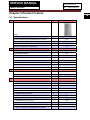
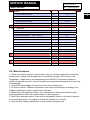
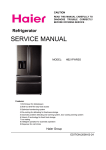
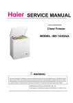
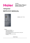
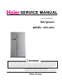
SERVICE MANUAL Order No. Ref0904S004V1 Refrigerator MODEL: HRF-660S WARNING This service information is designed for experienced repair technicians only and is not designed for use by the general public. It dose not contain warnings and cautions to advice non-technical individuals of potential dangers in attempting to service a product. Product powered by electricity should by serviced or repaired only by experienced professional technicians. Any attempt to service or repair the product or products dealt with in this service information by anyone else could result in serious injury or death. ◎2010 (HAIER ELECTRICAL APPLIANCES COR. LTD) All right reserved. Unauthorized copying and distribution is a violation of law. Haier Group SERVICE MANUAL Model: HRF-660S Issue 2010-06-21 Rev. Ref0904S004V1 Contents Table of Contents ·········································································································· 1 1. General Information·································································································· 4 1-1. General guideline ······························································································· 4 1-2. Insurance test····································································································· 4 1-3. How to read this Service Manual········································································ 5 2. Product Feature ········································································································ 6 2-1. Specifications ····································································································· 6 2-2. Main functions ···································································································· 7 2-3. External views ···································································································· 8 3. Disassembly and Installation ·············································································· 9 3-1. Door and handle································································································· 9 3-2. Lamp switch ······································································································· 9 3-3. Wind passage cover assembly and lamp in fridge chamber······························ 9 3-4. Wind passage cover assembly and lamp in freezer chamber ·························· 10 3-5. Control panel box ····························································································· 11 3-6. Display panel ···································································································· 11 4. Control and Display System ····················································································12 4-1. Display control board························································································ 12 4-2. Control function display ···················································································· 12 4-3. Fuzzy mode ······································································································ 12 4-4. Open-door warning··························································································· 12 4-5. Malfunction display ····························································································12 4-6. Fridge ON / OFF function ··················································································13 4-7. Quick freezer function ·······················································································13 4-8. Fridge lamp control ···························································································13 5. Control principal and related test functions·························································· 14 5-1. Air Damper······································································································ 14 5-2. Control principle of fan motor·········································································· 14 5-3. Defrost control································································································· 14 2 SERVICE MANUAL Model: HRF-660S Issue 2010-06-21 Rev. Ref0904S004V1 5-4. Self-testing function·························································································15 6. System flow principle ······························································································· 16 6-1. System flow scenograph················································································· 16 6-2. System flow chart···························································································· 16 7. Circuit diagram·········································································································· 17 7-1. Main control PCB diagram ·············································································· 17 7-2. Brief principle diagram ···················································································· 18 7-3.Sensor and error codes ··················································································· 18 8. Trouble shooting ·······································································································20 8-1. Frequently problem ························································································· 20 3 SERVICE MANUAL Model: HRF-660S Issue 2010-06-21 Rev. Ref0904S004V1 Chapter 1 General Information 1-1. General Guidelines When servicing, observe the original lead dress. If a short circuit is found, replace all parts which have been overheated or damaged by the short circuit. After servicing, see to it that all the protective devices such as insulation barriers, insulation papers shields are properly installed. After servicing, make the following leakage current checks to prevent the customer from being exposed to shock hazards. 1) Leakage Current Cold Check 2) Leakage Current Hot Check 3) Prevention of Electro Static Discharge (ESD) to Electrostatic Sensitive 1-2. Insurance test 1. Check if there is any leak of current. 2. Cut out the power supply before the repair to avoid an electrical shock hazard. 3. In the case of a live-line test, insulating gloves should be worn to avoid potential electrical shock. 4. Confirm the rated current, voltage and capacity before testing with any kinds of instruments. 5. Watch if the upper door is open when you check something at a lower position. 6. Take out every part in the cabinet before moving the machine, especially things like panels (e.g. glass shelf). 7. Please wear intact cotton gloves when repair any parts of the evaporator, so that scratches by the sharp fins can be avoided. 8. If there is a breakdown with the refrigeration system, please surrender the machine to the service center, else the leaked refrigerant may pollute the atmosphere. 9. The refrigerator use AC of 220V with a frequency of 50~60Hz. 10. A big fluctuation of voltage (exceed the range 187~242V) may cause a start failure of the refrigerator, a burn-out of the control panel and compressor, or an abnormal sound from the compressor in operation. In this condition an automatic voltage regulator over 60W should be added. 11. Take care not to damage the supply line. Don’t yank at the line; pull the plug out gently from the receptacle. Don’t press the line under the cabinet or step on it. Take care not to roll on or damage the supply line when moves the machine from the wall. 12. In the case of leakage of inflammable gases like carbon monoxide, open the door and windows. Don’t pull out or insert the plugs of the appliance. 13. Don’t touch the refrigeration surface of the freezing compartment when the refrigerator is in operation, especially when your hand is wet, else you may be glued to the surface. 14. Pull out the plug of power supply during clearance or power outage. Wait at least five minutes to resume the power supply in order to prevent damage to the compressor caused by continuous restart. 4 SERVICE MANUAL Model: HRF-660S Issue 2010-06-21 Rev. Ref0904S004V1 Photo used in this manual The illustration and photos used in this Manual may not base on the final design of products, which may differ from your products in some way. 1-3. How to read this Service Manual 1-3-1. Using Icons The meaning of each icon is described in the table below: Note: A “note” provides information that is not indispensable. Caution: A “caution” is used when there is danger, through incorrect manipulation, may damage equipment, loose data, get an unexpected result or has to restart (part of) a procedure. Warning: A “warning” is used when there is danger of personal injury. Reference: A “reference” guides to find additional information on a specific topic. 5 SERVICE MANUAL Model: HRF-660S Issue 2010-06-21 Rev. Ref0904S004V1 Chapter 2 Product Feature 6 2-1. Specifications 1 Model HRF-663DTA2 Photo Product description (Refrigerator/Freezer) Refrigerator-Freezer Type of appliance (FS=freestanding / BI= built-in) FS Type of cooling system(NF=no frost/ S=static) NF Climate class* SN.N.ST Freezer compartment / Star rating 2 4* Key features Total gross volume L 582 Total storage volume L 530 Defrosting (M=manual A=automatic) A Frost free system yes Defrost water outlet yes Air circulating ventilator yes Kind of coolant R134a/ 180g Foaming components 3 C-P Technical data Voltage / frequency Input power V/Hz 220V-240V~/ 50 W 200 Cooling system: K=Compressor / A=Absorption 4 K Door: F= flat / R= rounded / S= streamline S Inside color w Hinged (r =right l =left) / reversible R/L Freezing compartment integrated with door No Shelves: Number Fridge / Freezer Type n° (gr=grill / g=glass / p=plastic) 4/g/P Color w-white / g=green / t=transparent. t Adjustable (Y=yes / N=not) Yes Crisper: Number Fridge / Freezer Color of crisper(s) ( t=transparent / w=white) n° 2/t SERVICE MANUAL Model: HRF-660S Issue 2010-06-21 Rev. Ref0904S004V1 Drawer: Number Fridge / Freezer n° Color of drawer(s) ( t=transparent / w=white) -/2 t Bottle holder: Number Fridge / Freezer n° Color of bottle holder(s)( t=transparent / w=white) 5 t Equipment & accessories Con trol panel: Interior / exterior Interior Thermometer interior / exterior Over temperature alarm Interior LED / acoustic Yes Adjustable thermostat Yes Fast freeze switch /-function Yes Deodorizing Yes Interior light W ice maker Manual/ Automatic Adjustable feet front / rear 7 Yes M n° Castors front / rear 6 5/4 2 /FRONT -/yes Product dimensions Unit dimensions ( H / W / D) mm 1768/890/770 Net weight kg 120 Service User manual Multi-Languages 2-2. Main Functions 1. Whole air-cooled computer control system, there is a freezer evaporator and a fan in freezing room, fridge room through the air circulation blowing by fan to carry on the refrigeration,, fridge room is controlled through the ON/OFF of electronic damper to achieve temperature control, control freezing room temperature through the run and stop of compressor. 2. Large LED digital display to show each inner room temperature。 3. AI control function. Chamber temperature can control automatically according to the ambient temperature, and no need human intervene. 4. Malfunction self-diagnosis function. It can shows error codes automatically to help solving problems in time when system does not work properly. 5. Open-Door warning function: If the door is not properly closed, or the door is opened for an extended period , the appliance buzzer will sounds at an interval. 6. Ultra-thin door design, appearance is more concise and generous. 7 SERVICE MANUAL Model: HRF-660S 2-3. External views Issue 2010-06-21 Rev. Ref0904S004V1 8 SERVICE MANUAL Model: HRF-660S Issue 2010-06-21 Rev. Ref0904S004V1 Chapter3 Disassembly and Installation 3.1. Door and handle 1. Loosen the screw by screwdriver, and then remove the hinge cover from upper way. 2. Loosen the screw fixing the upper hinge to the body and lift the door. 3. Door gasket can be pulled out from door foam assembly . 4. Fix the bolt into the hole on the door, and then use the handle aiming to the bolt, push the handle down until it touch the door firmly. 3.2. Lamp Switch 1. To remove the switch pulls out it with a flat type screwdriver as shown in. 2. Disconnect the lead wire from switch. 3.3. Wind passage cover assembly and lamp in fridge chamber 1. Unplug the power cord from the outlet; 2. Remove the fridge shelf; 3. Remove the lamp cover ; 4. The bulb can be replaced; 9 SERVICE MANUAL Model: HRF-660S Issue 2010-06-21 Rev. Ref0904S004V1 5. Loosening 2 screws fixed to ceiling of inner liner; 6. Pull out the electric damper, wind passage and the wind passage cover; 7. After replaced the disabled parts, assemble in reverse order of disassembly. 3.4. Wind passage cover assembly and lamp in freezer chamber 1. Unplug the power cord from the outlet; 2. Remove the freezer shelf; 3. Remove the lamp cover; 4. The bulb can be replaced; 5. Loosening 2 screws fixed the cover and pull out the top freezer air tower; 6. Pull out the bottom freezer air tower and unplug the sensor cable; 7. Pull out the freezer rack, unplug the fan motor cable and separate the fan motor cover and the rack. 8. Pull out the freezer air shutter; 9. Unplug the defrost sensor cable and replace it; 10. Assemble in reverse order of disassembly. 10 SERVICE MANUAL Model: HRF-660S 3.5. Control panel box 1.Unplug the power cord from the outlet; 2.Lossening 4 screws fixed the control panel box cover; 3.Open the cover; 4. Replace or check the control panel if necessary. 3.6. Display panel 1.Unplug the power cord from the outlet; 2.Lossening 2 screws fixing the bottom of control panel assembly; 3.Unplug the display panel; 4.Lossening 4 screws fixing the control panel. Issue 2010-06-21 Rev. Ref0904S004V1 11 SERVICE MANUAL Model: HRF-660S Issue 2010-06-21 Rev. Ref0904S004V1 Chapter 4 Control and display system (1) Display control board (2) Control function display 30 minutes later after the final press of button, display will be blank. Previous display can be resumed if any button is pressed or any door opened. (3) Fuzzy mode If fuzzy mode is activated, the appliance will adjust inside temperature automatically according to ambient temperature. Fuzzy mode is activated and inactivated by consecutive press of button A, then light E will be turned on and off. NOTE: Fridge temperature can not be adjust in Fuzzy mode. (4) Open-door warning If the door is not properly closed, or the door is opened for an extended period (more than 60 seconds), the appliance buzzer will send out 3 alarm sounds at an interval 30 seconds, until the door is closed properly. (5) Malfunction display If control or function system does not work properly, information of refrigerator or freezer compartment temperature will not be display, This will not affect the cooling effect in short period of 12 SERVICE MANUAL Model: HRF-660S Issue 2010-06-21 Rev. Ref0904S004V1 time. User should contact authorized after-sales service for technical assistance in time. 13 (6) Fridge ON/OFF function Hold button D pressed for 3 seconds, the refrigerator performance ceased and icon H goes out, leaving refrigerator light under normal status. If refrigerator performance ceased, hold refrigerator temperature button D for 3 seconds again, icon H will appear and refrigerator performance will be resumed. (7) Quick freeze function Press button B, indicator F lights, and super freeze mode is activated. If button B is press again, indicator F goes out and super freeze mode is inactivated. Super freeze function is designed to preserve the nutritional value of food, as the food will freeze completely in the shortest period possible with compressor continual running. The appliance will exit super freezer mode after continual running for 4 hours. NOTE: Freezer temperature can not be adjust in Super Freezer mode. (8) Fridge lamp control When the fridge door is open, lamp will be light, and if keep the door open more than lamp will extinguish automatically. 7 minutes, SERVICE MANUAL Model: HRF-660S Issue 2010-06-21 Rev. Ref0904S004V1 Chapter 5 Control principal and related test functions 5-1. Air damper 1) Refrigerating sensor R1 controls the startup and shutdown of air damper in refrigerator compartment. 2)The air damper is closed (in order to prevent the compartment from freezing) within 15 minutes from the beginning to the finishing of defrosting. 3) Force the air damper to be opened and closed once if it can not be opened within 1 hour. After that, decide whether open or close it according to R1 sensor. 4) The air damper heater and ice dispenser heater work in-phase. 5) Environment temperature is above 12 ℃, the heater of bar will be on, when lower than 10 ℃, heater will be off. 6) Dispenser heater and water drain pipe heater will be off for 10 minutes and 30 minutes on, thus a circulation. 5-2. Control principle of fan motor Control of freezing fan: When open the refrigerating door, the refrigerating air damper will be turned on, and the freezing fan will be working, after 2 minutes the refrigerating air damper will be turned off. When open the freezing door, If the freezing fan works at a speed of 1500 RPM, the freezing fan will keep working but switch to 1300 RPM. If the fan works at a speed of 1300 RPM, it will shut off when the freezing door is open. Control of refrigerating fan: This fan is working in-phase with the compressor and at a fixed speed of 1100 RPM. 5-3. Defrost control Automatic defrost: After added up to 7 hours of compressor running, defrost will be switched on. When defrost SNR temperature reaches 7℃, defrost will be over. If the defrosting time is more than 120 minutes, and defrost sensor still can not reach to 7ºC, it will stop defrosting process and give warning error indicator—display error code F6.. Easily failure components of defrosting system: 1)Defrosting fuse: It is located in the left side of evaporator. If the fuse is open circuit, means it is defective. 2)Connectors: The frequently failure phenomenon is that pin of connectors is dislocation or oblique. 3)Defrosting sensor: It is located in the upper right side of evaporator, the sensor control the defrosting time. 14 SERVICE MANUAL Model: HRF-660S Issue 2010-06-21 Rev. Ref0904S004V1 5-4. Self-testing function About self-test function: (1) With self-test function, the appliance can quickly check the working condition of fan, compressor and defrost heater. (2) How to enter and quit: press the test button on the main control board once, and enter the forced starting mode, and a second time press to enter forced defrosting mode. MODE OPERATION WORKING CONDITION 15 TEST button REMARKS (1) compressor forced start. TEST1 Press test button once to enter Forced Start mode. (2) freezing fan work at high speed (3) refrigerating fan work (4) heater shut down Press test button two times to quit this mode. (5) air escaper opens TEST2 Resume normal mode Under test 1 and press test button again to enter Forced Defrost mode. (1) compressor shut down (2) no fan works (3) Defrost heater works Press test button one time to quit this mode. (4) air escaper closes Press test button for Resume to normal mode and the compressor will start in 7 a third time. minutes. SERVICE MANUAL Model: HRF-660S Issue 2010-06-21 Rev. Ref0904S004V1 Chapter 6 System flow principle 16 6-1.System flow scenograph (1)Compressor (2)Condenser (3)Hot connector pipe for freezer (4)Hot connector pipe for fridge (5)Drier filter (6)Capillary tube (7)Evaporator (8)Suction pipe (9)Compressor DC fan motor (10)Freezer DC fan motor This product adopts an air-cooled refrigeration system to ensure accurate refrigeration in freezer compartment and refrigeration compartment. 6-2.System flow chart SERVICE MANUAL Model: HRF-660S Chapter 7 Chapter 7 Circuit Circuit diagram diagram 7-1. Main control PCB diagram Issue 2010-06-21 Rev. Ref0904S004V1 17 SERVICE MANUAL Model: HRF-660S 7-2. Brief principle diagram 7-3. Sensors and error codes Sensor Location: Issue 2010-06-21 Rev. Ref0904S004V1 18 SERVICE MANUAL Model: HRF-660S Sensor Sensor name marker Sensor location Issue 2010-06-21 Rev. Ref0904S004V1 Function measure the temp. of the RT sensor RT SNR under the right hinge box Refrigerator sensor 1 R1 SNR beside the air-vent in REF Refrigerator sensor 2 R2 SNR on the right side of the REF cabinet Defrosting sensor D SNR on the top of the evaporator in FRZ measure the temp. of the evaporator Freezer sensor F SNR middle of freezer compartment circumstance measure the temp. of the air measure the temp. of the REF compartment measure the temp. of the FRZ compartment Error code list: NO Malfunction Error Indicator F SET F4 Error code meaning R SET 1 F SNR failure normal F SNR is short circuit or open circuit 2 RT SNR failure normal F3 RT SNR is short circuit or open circuit 3 R1 SNR failure normal F1 R1 SNR is short circuit or open circuit 4 R2 SNR failure normal F2 R2 SNR is short circuit or open circuit 5 D SNR failure normal F6 D SNR is short circuit or open circuit 6 Freezer fan motor failure normal E1 more than 30 seconds without signal 7 Condenser fan motor failure normal E2 more than 30 seconds without signal 8 failure communication normal E0 No reflect when setting ,between display PCB and Power PCB no signal transmitted over 2 min 9 Defrosting system failure normal Ed can not reach -12℃ within 2 hours 19 SERVICE MANUAL Model: HRF-660S Issue 2010-06-21 Rev. Ref0904S004V1 Chapter 8 Trouble shooting 8.1. Frequently problem Water/moisture/frost in the refrigerator Moisture accumulates Hot and moist climate. Accumulation of frost and moisture on the refrigerators The door is not closed accelerate in such climate. inner walls tightly Make sure the refrigerator is level and The door is opened too there is no food or container interfering frequently or for too with the door long time Do not open the door so frequently Water/moisture/frost on outside surface of the refrigerator Moisture accumulates Damp climate It is normal in damp climate. The moisture on the refrigerator’s The refrigerator door is will decrease when the humidity drops. outside surface or not closed tightly. This Make sure the refrigerator is level and between two doors causes mixing of the there is no food or container interfering cold air in the with the door refrigerator with the warm air outside it Refrigerator operation The compressor does The refrigerator is in It is normal for an automatic defrosting not work defrosting cycle. refrigerator. The refrigerator is not Verify the plug is plugged in the socket plugged into a power firmly. outlet. Press the “Power” button for 3 second or The refrigerator is in more to restart the refrigerator or turn the OFF state. knob from OFF to temperature selection position. The fridge storage The air door cable is not Check if the air door cable is not compartment does not connected properly. connected properly and install it correctly work if not so. Verify that the air door acts normally with the Fridge ON/OFF key on The fan does not work the display panel The fan does not work while the refrigeration air door is open. Please check if the door on-off behind the front The fridge storage decoration strip is installed properly. compartment is turned Reinstall it correctly if not so. off Turn on the fridge storage compartment manually The refrigerator runs The indoor or outdoor In this case, it is normal for the frequently or runs for temperature is high refrigerator to run longer. too long period The refrigerator has Normally, it takes 8 to 12 hours for the been powered off for a refrigerator to totally cool down. period of time. Icemaking process makes the refrigerator The automatic icemaker to run longer. is operating. Warm air enters the refrigerator and The door is opened too causes it to start frequently. Please do not frequently or for long open the door so frequently. periods. Make sure the refrigerator is level place The door of the fridge / and there is no food or container freezer storage interfering with the door. compartment is not Set the temperature higher until tightly closed. satisfactory refrigerator temperature is The temperature setting obtained. It takes 24 hours for the for the freezer storage refrigerator temperature to become compartment is too low stable. 20 SERVICE MANUAL Model: HRF-660S Too high temperature Too high temperature in the fridge/freezer storage compartment Issue 2010-06-21 Rev. Ref0904S004V1 The door gasket of the fridge/freezer storage compartment is dirty, worn, cracked or mismatched. The condenser is dirty. Clean the condenser. The door is opened too frequently or for too long periods of time Temperature is set too high The door is not closed tightly The condenser is dirty The temperature is set too high Warm air will enter the refrigerator whenever the door is opened. Try to open the door as infrequently as possible. Reset the temperature. Make sure the refrigerator is on a level surface and there is no food or container interfering with the door. Clean the condenser. Set the freezer temperature lower. It takes 24 hours for the temperature of the refrigerator to become stable. The temperature in the freezer storage compartment is too high while the temperature in the fridge storage compartment is OK The temperature in the The temperature is set fridge storage too high compartment is too high while the temperature in the freezer storage compartment is OK Bad odors in the refrigerator The inside of the The inside of the refrigerator is dirty refrigerator needs cleaning Food with strong odor is stored in the refrigerator If you hear... Beeps The fridge storage compartment door is open The temperature in the freezer storage compartment is too high Abnormal sound The refrigerator is not located on a level surface The refrigerator touches some object around it Slight sound similar to It is the sound of the that of flowing water refrigerating system Heating of cabinet The de-dew tube is de-dewing Clean or replace the door gasket. Leakage gap of door gasket can cause longer running time of the refrigerator in order to maintain desired temperature. Set the fridge temperature lower. It takes 24 hours for the temperature of the refrigerator to become stable. Clean the internal of the refrigerator Wrap the food tightly. Close the door or silence the alarm manually The alarm is normal when it is first started due to relatively higher temperature. Adjust the feet to level the refrigerator. Remove objects around it. Normal. It is a process to prevent dewing. It is a normal phenomenon. 21 Sincere forever Haier Group Haier Industrial Park, No.1, Haier Road 266101, Qingdao, China http://www.haier.com