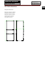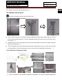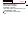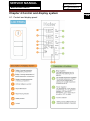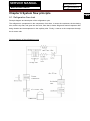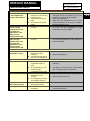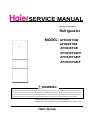
1
SERVICE MANUAL Order No. Ref1010S025V0 Refrigerator MODEL: AFD626TGW AFD626TGB AFD626TGR AFD626TGW/F AFD626TGB/F AFD626TGR/F WARNING This service information is designed for experienced repair technicians only and is not designed for use by the general public. It dose not contain warnings and cautions to advice non-technical individuals of potential dangers in attempting to service a product. Product powered by electricity should by serviced or repaired only by experienced professional technicians. Any attempt to service or repair the product or products dealt with in this service information by anyone else could result in serious injury or death. ©2010 (HAIER ELECTRICAL APPLIANCES COR. LTD) All rights reserved. Unauthorized copying and distribution is a violation of law. Haier Group SERVICE MANUAL Model:AFD626TGW/R/B Issue 2010-10-25 Rev. Ref1010S025V0 Contents Table of Contents ········································································································ 2 1. General Information ································································································ 4 1-1. General guideline ····························································································· 4 1-2. Insurance test ··································································································· 4 1-3. How to read this service manual ······································································· 5 2. Product Feature ······································································································ 6 2-1. Specifications ··································································································· 6 2-2. Main functions and features ·············································································· 8 2-3. External views ·································································································· 9 2-4. Product dimensions ························································································ 10 3. Disassembly ·········································································································· 11 3-1. Remove the variable temperature compartment drawer ·································· 11 3-2. Remove the display panel ··············································································· 11 3-3. Remove the rolling shelf ················································································· 11 3-4. Remove the air-duct························································································ 12 3-4-1. Removal of fridge air-duct ········································································ 12 3-4-2. Removal of freezing air-duct ···································································· 12 4. Control and Display System ····················································································· 14 4-1. Control and display panel ··············································································· 14 4-2. Error code display and sensor positions ························································· 18 4-2-1. Error code display ···················································································· 18 4-2-2. Graphic display of the sensor location ······················································ 19 4-3. TEST MODE ··································································································· 20 5. Control Principle of Electronic Component ·························································· 22 5-1. Air damper ······································································································ 22 5-2. Control principle of the freezer fan motor ························································ 22 5-3. Control principle of the fridge fan motor ·························································· 22 5-4. Defrosting control principle·············································································· 22 2 SERVICE MANUAL Model:AFD626TGW/R/B Issue 2010-10-25 Rev. Ref1010S025V0 6. System Flow Principle ···························································································· 23 6-1. Refrigeration flow chart·················································································· 23 6-2. Perspective of the refrigeration system ·························································· 23 6-3. Air flow scenograph ······················································································· 25 7. Circuit Diagram ······································································································· 26 7-1. Main control PCB diagram ············································································· 26 7-2. Main control PCB connections······································································· 27 8. Trouble Shooting ···································································································· 29 8-1. Common problems and solutions ·································································· 29 8-1-1. No defrosting ·························································································· 29 8-1-2. Neither display nor start when powering on ············································ 29 8-1-3. Poor freezing effect accompanied by loud noise ····································· 29 8-2. Examination and solutions for other problems ··············································· 30 3 SERVICE MANUAL Model:AFD626TGW/R/B Issue 2010-10-25 Rev. Ref1010S025V0 Chapter 1 General Information 1-1. General guidelines When servicing, observe the original lead dress. If a short circuit is found, replace all parts which have been overheated or damaged by the short circuit. After servicing, see to it that all the protective devices such as insulation barriers, insulation papers shields are properly installed. After servicing, make the following leakage current checks to prevent the customer from being exposed to shock hazards. 1) Leakage Current Cold Check 2) Leakage Current Hot Check 3) Prevention of Electro Static Discharge (ESD) to Electrostatic Sensitive 1-2. Insurance test 1. Check if there is any leak of current. 2. Cut out the power supply before the repair to avoid an electrical shock hazard. 3. In the case of a live-line test, insulating gloves should be worn to avoid potential electrical shock. 4. Confirm the rated current, voltage and capacity before testing with any kinds of instruments. 5. Watch if the upper door is open when you check something at a lower position. 6. Take out every part in the cabinet before moving the machine, especially things like panels (e.g. glass shelf). 7. Please wear intact cotton gloves when repair any parts of the evaporator, so that scratches by the sharp fins can be avoided. 8. If there is a breakdown with the refrigeration system, please surrender the machine to the service center, else the leaked refrigerant may pollute the atmosphere. 9. The refrigerator use AC of 220V with a frequency of 50Hz. 10. A big fluctuation of voltage (exceed the range 187~230V) may cause a start failure of the refrigerator, a burn-out of the control panel and compressor, or an abnormal sound from the compressor in operation. In this condition an automatic voltage regulator over 750W should be added. 11. Take care not to damage the supply line. Don’t yank at the line; pull the plug out gently from the receptacle. Don’t press the line under the cabinet or step on it. Take care not to roll on or damage the supply line when moves the machine from the wall. 12. In the case of leakage of inflammable gases like carbon monoxide, open the door and windows. Don’t pull out or insert the plugs of the appliance. 13. Don’t touch the refrigeration surface of the freezing compartment when the refrigerator is in operation, especially when your hand is wet, else you may be glued to the surface. 14. Pull out the plug of power supply during clearance or power outage. Wait at least five minutes to resume the power supply in order to prevent damage to the compressor caused by continuous restart. 4 SERVICE MANUAL Model:AFD626TGW/R/B Issue 2010-10-25 Rev. Ref1010S025V0 Photo used in this manual The illustration and photos used in this Manual may not base on the final design of products, which may differ from your products in some way. 1-3. How to read this service manual 1-3-1. Using Icons The meaning of each icon is described in the table below: Note: A “note” provides information that is not indispensable, but may nevertheless be valuable to the reader, such as tips and tricks. Caution: A “caution” is used when there is danger, through incorrect manipulation, may damage equipment, loose data, get an unexpected result or has to restart (part of) a procedure. Warning: A “warning” is used when there is danger of personal injury. Reference: A “reference” guides to other places in this binder or in this manual, where we will find additional information on a specific topic. 5 SERVICE MANUAL Model:AFD626TGW/R/B Issue 2010-10-25 Rev. Ref1010S025V0 Chapter 2 Product Feature 6 2-1. Specifications 1 Models AFD626TGW AFD626TGW/F AFD626TGB AFD626TGB/F AFD626TGR AFD626TGR/F Sketch Product description Refrigerator (Refrigerator/Freezer) Type of appliance (FS= freestanding/BI= built-in) FS FS FS Type of cooling system(NF=no frost/ S=static) NF NF NF SN N ST SN N ST SN N ST 4* 4* 4* Climate class* Freezer compartment / Star rating 2 Key features Gross capacity L 298 298 298 Total net capacity L 254 254 254 Net capacity refrigerator compartment L 160 160 160 Net muti-use compartment L 34 34 34 Net capacity freezer compartment /ice compartment L 60 60 60 Freezing capacity kg 12kg 12kg 12kg Energy consumption / year kWh 259 259 259 Max storage time at breakdown Freezer Min 820 820 A A A Frost free system yes yes yes Defrost water outlet yes yes yes Air circulating ventilator yes yes yes R600a/ 68g R600a/ 68g R600a/ 68g Defrosting (M=manual Kind of coolant 3 820 A=automatic) (R134a/R600a) Technical data Voltage / frequency V/Hz 220-240~/ 50 220-240~/ 50 220-240~/ 50 Input power / mains fuse minimum W /A 100/ (DC) 100/ (DC) 100/ (DC) Refrigerator 2-10°C 2-10°C 2-10°C Muti-use compartment 5~-18°C 5~-18°C 5~-18°C - Temperature range (from>to) °C SERVICE MANUAL Model:AFD626TGW/R/B Issue 2010-10-25 Rev. Ref1010S025V0 2-10°C 2-10°C 2-10°C -16 ~-26°C -16 ~-26°C -16 ~-26°C kWh 102 102 102 kWh 0.28 0.28 0.28 K K K 42 42 42 W BLACK RED G/G G/G G/G R R R w w w n° 3 3 3 n° 4 4 4 (r =right l =left) / reversible r/X r/X r/X Fridge / Freezer 3/- 3/- 3/- g g g t t t N N N Foldable Shelf yes yes yes Bottle Rack yes yes yes Vegetable Crisper Freezer Features: Energy consumption per l 100 net / year Energy consumption per l 100 net / 24h Cooling system: K=Compressor / A=Absorption dB(A Max noise level ) 4 Aesthetics Colors: W=white G=silver gray B=Obsidian SS=stainless steel Fascia panel / Handle (w / c) F= flat / R= rounded / S= streamline Inside colour Compartments number Bottle compartment Hinged Shelves: Number Type Color (gr=grill / g=glass / p=plastic) w-white / b=blue / t=transparent. Adjustable (Y=yes / N=not) Drawers: Plastic drawers (fully freezing comp.) n°. 3 3 3 Muti-use comp n°. 2 2 2 t t t Chiller (t) Chiller (t) Chiller (t) t t t Exterior Exterior Exterior Interior Interior Interior LCD LCD LCD W W W acoustic acoustic acoustic Adjustable thermostat yes yes yes Fast freeze switch /-function yes yes yes yes yes yes Colour of drawer (w=white/t=transp./g=green) Crisper: Chiller / Meat (salad crisper) transparent / white Vegetable crisper(s) 5 transparent / white Equipment & accessories Control panel Interior / exterior Thermometer interior / exterior Display type Control lamps green / yellow /white Over temperature alarm LED / acoustic Deodorizing Interior light W yes yes yes LED light n° Full Full Full 7 SERVICE MANUAL Model:AFD626TGW/R/B n° Issue 2010-10-25 Rev. Ref1010S025V0 3 3 3 M M M 1 1 1 yes yes yes 2 2 2 n° 2/- 2/- 2/- cm 200 200 200 I I I cm 180/63/64 180/63/64 180/63/64 Depth Without handle cm 64 64 64 Depth with open door cm 119 119 119 Door open angle n° <135 <135 <135 Net weight kg 78 78 78 cm 185.5/74.7/71.4 185.5/74.7/71.4 185.5/74.7/71.4 Gross weight kg 92 92 92 40 ' Container load pcs 54 54 54 40 ' HC Container load pcs 72 72 72 RS RS RS RS 6270 6270 6270 Freeze pack(s) ice maker Manual/ Automatic n° Ice cube tray(s) Butter holder Egg trays Adjustable feet front / rear Length of cable/incl. plug Condenser Product 6 Back wall / Integrated dimensions Unit dimensions ( H / W / D) Packing dimensions & load ability 7 Packing dimensions (H / W / D) Recycling symbols 8 Packing materials / Recycling symbols (RS) Carton weight in gr Polystyrene weight in gr 06 2570 2570 2570 Polyethylene foil weight in gr 04 210 210 210 Service 9 Users instruction (languages) D / F / I / GB / E / P / NL 2-2. Main functions and features ◆ Full-frequency technology. ◆ Artificial intelligent automatic regulation of the temperature. ◆ Over-temperature alarm. ◆ Full temperature range of the variable temperature compartment ◆ LCD display. ◆ Holiday function. 8 SERVICE MANUAL Model:AFD626TGW/R/B Issue 2010-10-25 Rev. Ref1010S025V0 2-3. External views 9 Refrigerator structure Fridge storage compartment Cover for medium bottle rac LED light Shelf Rolling Shelf Rack for medium bottles Sealing box Rack for small bottles Shelf Fruit and vegetable drawer Rack for big bottles Drawer in variable temperature compartment Freezing drawer Power plug SERVICE MANUAL Model:AFD626TGW/R/B Issue 2010-10-25 Rev. Ref1010S025V0 2-4. Product dimensions 10 Refrigerator Dimensions: Refrigerator height H=1805mm Refrigerator width W=630mm Refrigerator depth D=640mm Cabinet depth D1=560mm Door depth D2=70mm D W H D2 D1 SERVICE MANUAL Model:AFD626TGW/R/B Issue 2010-10-25 Rev. Ref1010S025V0 Chapter 3 Disassembly 3-1. Remove the variable temperature compartment drawer (1) Open the variable temperature compartment door (fig. ①); (2) Remove 4 connectors of the drawer (fig. ②); (3) Pull out 2 drawers from the cabinet (fig. ③). 3-2. Remove the display panel ① ② ④ ③ ⑤ (1) Detach 2 screws fixing on the top cover of the fridge door (fig. ①); (2) Remove the top cover of the fridge door (fig. ②); (3) Detach 2 screws fixing on the display panel box (fig. ③); (4) Pull out the shelf of display panel and disconnect the connector of the display panel (fig. ④). (5) Detach 2 screws fixing on the display panel shelf (fig. ⑤) 3-3. Remove the rolling shelf ① ② 11 SERVICE MANUAL Model:AFD626TGW/R/B Issue 2010-10-25 Rev. Ref1010S025V0 (1) slide in the rolling shelf (fig. ①); (2) Detach 2 screws of the rolling shelf (fig. ②); 12 3-4. Remove the air-duct Unplug the refrigerator before removing the air-duct 3-4-1. Removal of fridge air-duct connector Duct cover Lamp cover Lamp connector ③ ② ① (1) Take out the accessories in the fridge storage compartment which may interfere with the removal of the air-duct (including shelves, Fruit and vegetable drawer).Tilt 2 lamp covers in the lower of the air-duct (fig. ①); (2) Detach the duct cover in the upper part of the air-duct and detach 4 screws in the upper and lower part of the air-duct (fig. ②); (3) Tilt the refrigeration air-duct forward entirely around its upper side until you can see the connector on its upper side. Pull out the connector and you can remove the refrigeration air-duct (fig. ③); 3-4-2. Removal of freezing air-duct ① ② ③ ④ ⑤ ⑥ ⑦ ⑧ (1) Take out drawers in the variable temperature compartment and freezer storage compartment SERVICE MANUAL Model:AFD626TGW/R/B Issue 2010-10-25 Rev. Ref1010S025V0 which may interfere with the removal of the freezing air-duct . (2) detach 4 screws in lower of the middle clapboard (fig ①); (3) Disconnect the connector of the middle clapboard(fig ②); (4) Remove the middle clapboard from the lower ; (fig ③); (5) Detach the screw of the duct cover and remove it. (fig ④); (6) Pull out the connectors and disconnect them (fig ⑤); (7) Remove 4 small duct cover and detach 4 screws in the freezing air-duct onto the freezer chamber (fig ⑥); (8) Tilt the freezing air-duct forward from top to bottom and disconnect the connectors of the freezing air duct ,then you can remove the air-duct (fig ⑦); (9) Take out the freezing air-duct and the fin evaporator is just behind it (fig ⑧). When reinstalling, please connect the connector first and then mount and fix the freezing air-duct. 13 SERVICE MANUAL Model:AFD626TGW/R/B Chapter 4 Control and display system 4-1. Control and display panel Issue 2010-10-25 Rev. Ref1010S025V0 14 SERVICE MANUAL Model:AFD626TGW/R/B Issue 2010-10-25 Rev. Ref1010S025V0 ■Automatic temperature regulation of the refrigerator ●When the power is initially switched on, the refrigerator is in artificial intelligence mode (symbol I), the refrigerator will automatically regulate the temperature in the refrigerator compartments according to the ambient temperature. ●When the refrigerator is in the Unlock mode, pressing button D Function, and symbol I Artificial Intelligence is selected, the I symbol starts to flash. Press button E Setting to start the artificial intelligence mode, the symbol I is permanently displayed, indicating the artificial intelligence mode is operating. To stop the artificial intelligence mode press button E Setting and the symbol I will disappear indicating that the artificial intelligence mode has now stopped. ■Lock / Unlock If symbol N is displayed, the panel is locked. Press and hold button E Setting for 3 seconds, symbol N shall disappear, and the panel is unlocked. Hold button E Setting again for 3 seconds, symbol N is displayed and the panel is locked again. ■Holiday function In the unlocked mode pressing button D and selecting symbol M Holiday the symbol M will start to flash, press button E, symbol M will be permanent displayed indicating the holiday mode is operating. The fridge compartment will warm up to +17℃. CAUTION: Remove any food and drink from the fridge compartment that may spoil due to the compartment being warm. To cancel the holiday mode press button D select symbol M and press button E. Symbol M will disappear and the holiday mode stops. 15 SERVICE MANUAL Model:AFD626TGW/R/B Issue 2010-10-25 Rev. Ref1010S025V0 ■Regulation of fridge compartment temperature between 2℃ and 10℃ and ON/OFF control, when in unlocked mode. ●Pressing button A to adjust the temperature and symbol F will start flashing. ●Each press of button A, the temperature shall be increased by 1℃ and recycled between 2℃~10℃ -OF. When it is set to be at OF shift, the refrigerating chamber shall be closed while at other shifts, it shall be started. ●Each press of button A, the temperature selection will increased by 1℃ between OFF and 2℃ to 10℃. At the OFF selection the fridge compartment will be at ambient temperature. WARNING! The fridge compartment should not be set at a higher(warmer) temperature than 5℃ to keep bacteria growth to a minimum. The recommended temperature is 1℃ to 4℃. ■Regulation of variable temperature compartment between +5℃ and -18℃ and ON/OFF control, when in unlocked mode. ●Pressing button B to adjust the temperature and symbol G will start flashing. ●Each press of button B, the temperature selection will increase by 1℃ between OFF and +5℃ to -18℃. At the OFF selection the variable temperature compartment will be at ambient temperature. ●After the temperature is set, the system shall automatically confirm and save the temperature if no button operation is performed within 5 seconds; the symbol shall stop flashing, and the display shall return to the actual temperature. When the variable temperature chamber has attained its refrigerating effect, the set temperature shall be displayed. ■Regulation of freezer compartment temperature between -16℃ and -26℃ when in unlocked mode. ●Pressing button C to adjust the temperature and symbol H will start flashing. ●Each press of button C the temperature will decrease by 1℃ between -16℃ to -26℃. 16 SERVICE MANUAL Model:AFD626TGW/R/B Issue 2010-10-25 Rev. Ref1010S025V0 17 ●After the temperature is set, the system shall automatically confirm and save the temperature if no button operation is performed within 5 seconds; the symbol shall stop flashing, and the display shall return to the actual temperature. When the freezing compartment has attained its refrigerating effect, the set temperature shall be displayed. ■Rapid freezing ●The function of rapid freezing is designed for preservation of the nutrition of frozen foods, which shall help freeze foods through in the shortest loss of time. If a large amount of foods is frozen once, the rapid freezing function shall be started 24 hours in advance to reduce the temperature of the freezing compartment before the foods are put in. ●Under unlock state, by press button D Function Selection, symbol K Rapid Freezing can be selected and symbol K begins flashing, press button E Setting, symbol K shall be displayed and stop flashing, indicating the rapid freezing function of the freezing chamber is started. After 56 hours, it shall stop the rapid freezing state. Under rapid freezing, press button D, select symbol K, and press button E, and symbol K will disappear, indicating that the rapid freezing function has stopped. ■Rapid chill Under unlock mode, by pressing button D Function Selection, symbol J Rapid chill can be selected and symbol J begins to flash, and press button E Setting, symbol J shall be displayed and stop flashing, indicating the rapid chill function of the variable temperature chamber is started. Under such a state, the variable temperature chamber shall be operated according to the set shift, and its temperature shall be gradually changed to -18℃ or after 3 hours of rapid chill, it shall stop the rapid chill. Under rapid chill, press button D, select symbol J and press button E, and symbol J will disappear, indicating that the rapid chill function has stopped. SERVICE MANUAL Model:AFD626TGW/R/B Issue 2010-10-25 Rev. Ref1010S025V0 18 ■Display control The display screen will turn off automatically 30 seconds after an operation is finished. It will be lit up by opening the refrigerator door or pressing any key. ■Door open alarming When the fridge door is open for more than 1 minute, the buzzer will sound 3 beeps every 30 seconds. The buzzer can be silenced by closing the door. ■Over temperature alarm for the freezer storage compartment When the temperature of the freezer storage compartment is more than -3℃, the temperature of the freezer storage compartment that displayed on the display panel will flashing. 4-2. Error code display and sensor positions 4-2-1. Error code display Malfunction description Sign Display Malfunction of the fridge evaporator sensor RE SNR F1 Display panel Malfunction of the ambient temperature sensor AT SNR F2 Display panel R SNR F3 Display panel F SNR F4 Display panel C SNR F5 Display panel D SNR F6 Display panel / Ed Display panel Malfunction of the fridge storage temperature sensor Malfunction of the freezer storage temperature sensor Malfunction of the variable temperature compartment sensor Malfunction of the defrosting temperature sensor Malfunction of the defrosting Display position SERVICE MANUAL Model:AFD626TGW/R/B Issue 2010-10-25 Rev. Ref1010S025V0 4-2-2. Graphic display of the sensor location 19 Freezer Compartment: SERVICE MANUAL Model:AFD626TGW/R/B Issue 2010-10-25 Rev. Ref1010S025V0 4-3. TEST MODE 20 MODE OPERATION WORKING CONDITION REMARKS 1) The compressor and the fans shall do a high speed operation; 2) The damper is open; 3) The defrosting heater wire is disconnected. This can be used to test the refrigeration performance. TEST1 In the Unlock mode, press and hold button A+B+C on the door display panel at the same time for 3 seconds to enter the T1 MODE, the door display panel displays T1 T1 T1, and the refrigerator enters Forced Refrigeration Mode 1) The compressor and the fans and the damper are closed; 2) The defrosting heater is forced operated. This can be used to test the defrosting system TEST2 In the T1 MODE, press and hold the button A+B+C on the door display panel at the same time for 3 seconds to enter the T2 MODE, the door display panel displays T2 T2 T2, and the refrigerator enters Forced Defrosting Mode 1) The compressor and the fans and the damper and the defrosting heater are closed, 2) The clapboard heater and the cover board heater are forced operated. This can be used to test the clapboard heater and the cover board heater. TEST3 In the T2 MODE, press and hold the button A+B+C on the door display panel at the same time for 3 seconds to enter the T3 MODE, the door display panel displays T3 T3 T3, and the clapboard heater and the cover board heater enter Forced Heating Mode TEST4 In the T3 MODE, press and hold 1) The compressor and the / SERVICE MANUAL Model:AFD626TGW/R/B the button A+B+C on the door display panel at the same time for 3 seconds to enter the T4 MODE, the door display panel displays T4 T4 T4, and the refrigerator enters a Special Mode EXIT Issue 2010-10-25 Rev. Ref1010S025V0 freezer fan motor shall be forced operated, 2) The damper is open, 3) The defrosting heater wire is disconnected, 4) The fridge compartment operates normally. In the T4 MODE, press and hold The door display panel will the button A+B+C on the door resume normal display display panel at the same time for 3 seconds to Exit TEST MODE 21 / SERVICE MANUAL Model:AFD626TGW/R/B Issue 2010-10-25 Rev. Ref1010S025V0 Chapter 5 Control principle of electronic component 5-1. Air damper (1) The damper is controlled with the Variable temperature compartment sensor C SNR. (2) The damper is closed from the beginning of defrosting until at least 8 minutes after the defrosting is finished. (3) Upon initial powering on or resetting of the control panel, the damper conducts a close-and-open cycle before acting according to the control conditions in item (1). (4) The damper will be forced to conduct an open-and-close cycle if it has been closed for 1 hour. After that, its closing/opening will be controlled by C SNR. (5) If the temperature is still rising (or dropping) within 10 minutes after opening (or closing) of the air door, it will open (or close) once again. 5-2. Control principle of the freezer fan motor The freezer fan motor is controlled by the control panel according to the following conditions. The DC fan’s rotation speed is regulated with the input Voltage and the AC fan operates directly. (1) ON/OFF condition of the freezer fan motor is controlled with the Freezer storage temperature sensor F SNR; (2) ON/OFF condition of the freezer fan motor is same with the Compressor. 5-3. Control principle of the fridge fan motor The fridge fan motor is controlled by the control panel according to the following conditions. The DC fan’s rotation speed is regulated with the input Voltage and the AC fan operates directly. (1) ON/OFF condition of the fridge fan motor is controlled with the Fridge storage temperature sensor R SNR. (2) When the Fridge storage compartment door is open, the fridge fan motor will not run. 5-4. Defrosting control principle (1) A defrosting cycle will be started once the compressor has operated for 12-18 hours accumulatively. It will stop defrosting when the defrosting sensor detects a temperature over 10ºC. (2) The damper and the freezer fan motor is closed, the compressor stops during defrosting. (3) After initial powering on or resetting of the control panel, it will start the first defrosting cycle after the compressor has operated for 5 hours accumulatively. (4) It may enter the defrosting state when the defrosting sensor is malfunctiony (short-circuit or open-circuit). In this case, it will exit the defrosting state after 30 minutes. 22 SERVICE MANUAL Model:AFD626TGW/R/B Issue 2010-10-25 Rev. Ref1010S025V0 Chapter 6 System flow principle 6-1. Refrigeration flow chart Principle diagram and description of the refrigeration cycle The refrigerant is compressed in the compressor, from there, it enters the condenser, the de-dewing tube, and the dry filter, and goes into the valve, from there,it enters fridge and freeze evaporator after being throttled and decompressed in the capillary tube. Finally, it returns to the compressor through the air return tube. Principle diagram of the refrigeration cycle: 23 SERVICE MANUAL Model:AFD626TGW/R/B Issue 2010-10-25 Rev. Ref1010S025V0 6.2. Perspective of the refrigeration system 24 1.compressor 2.evaporator tube 3.condenser4.de-dewing tube 5.dry filter 6.valve 7.fridge capillary tube 8.fridge evaporator 9.freeze capillary tube 10.freeze evaporator 11.air return tube 12.air return connect tube SERVICE MANUAL Model:AFD626TGW/R/B Issue 2010-10-25 Rev. Ref1010S025V0 6.3 Air Flow Chart Schematic drawing and description of air circulation in the refrigerator air-duct Fridge compartment air flow chart Freezer compartment air flow chart 25 SERVICE MANUAL Model:AFD626TGW/R/B Chapter 7 Circuit diagram 7-1. Main control PCB diagram Issue 2010-10-25 Rev. Ref1010S025V0 26 SERVICE MANUAL Model:AFD626TGW/R/B Issue 2010-10-25 Rev. Ref1010S025V0 7-2. Main control PCB connections There are 5 connectors on the main control panel. CN1 is the connector for the sensors and the PWM. Its pins are: 1: GND; 2-4: Null; 5: Pin5 and pin1 connect to the variable temperature compartment sensor. We can test the sensor with these two wires. Its resistance in normal operation is between 10.9 and 25.19kΩ (correspond to -10℃~-25℃). The resistance at normal temperature is between 2.49 and 1.61kΩ (correspond to 20℃~30℃); 6: Pin6 and pin1 connect to the fridge evaporator sensor. We can test the sensor with these two wires. Its resistance in normal operation is between 6.35 and 3.88kΩ (correspond to 0℃~10℃). The resistance at normal temperature is between 2.45 and 1.58kΩ (correspond to 20℃~30℃); 7: GND; 8: Pin8 and pin7 connect to the fridge storage sensor. Resistance test is the same as the fridge evaporator sensor; 9: Pin9 and pin7 connect to the defrosting sensor. Resistance test is the same as the variable temperature compartment sensor; 10: GND; 11: Pin11 and pin10 connect to the freezer sensor. Resistance test is the same as the variable temperature compartment sensor; 12: PWM; CN2 is the connector for display panel, the door switch, the LED lights and ambient temperature sensor. Its pins are: 1: GND; 2: +5V; 3: Com-in; 4: Com-out; 5: Door switch signal;When the door is opened, GND and the signal wires are switch to conduction. When the door is closed, the wires are disconnected; 6:Pin6 and pin1 connect to the ambient temperature sensor. Resistance test is the same as the fridge evaporator sensor; 7: LED lights +12V; 8: LED lights GND; CN3 is the connector for the freezer fan motor and the damper. Its pins are: 1: Null; 2: Freezer fan motor GND; 3: Freezer fan motor +15V(MAX); 4-6: Null; 7-10: Damper motor; 27 SERVICE MANUAL Model:AFD626TGW/R/B Issue 2010-10-25 Rev. Ref1010S025V0 CN4 is the connector for the power cable and heaters and valve. Its pins are: 1: N; 2: L; 3: Null; 4: Defrosting heater. The resistance between it and the N is 345Ω±10%; 5: Valve; 6: Clapboard heater and cover board heater. The resistance between it and the N is 4033Ω±10%; CN5 is the connector for the fridge fan motor. Its pins are: 1-2: Null; 3: Fridge fan motor GND; 4: Fridge fan motor +15V(MAX). 28 SERVICE MANUAL Model:AFD626TGW/R/B Issue 2010-10-25 Rev. Ref1010S025V0 Chapter 8 Trouble shooting 8-1. Common problems and solutions 8-1-1 Symptom: no defrosting Check: 1) Remove the freezer fan cover plate to check if all the connectors are connected properly and test if there is 220V voltage output across the terminals of the heating wire. 2) Measure the resistance of the heating wire with a multimeter. It should be 345Ω around. 3) Measure the resistance of the defrosting fuses. If they’re zero, the fuses are OK. If they’re infinite, the fuses are malfunctioning. 4) If no malfunction is found in the above checks, please test the defrosting temperature sensor with a multimeter. 8-1-2 Symptom: neither displaying nor starting when powering on Check: 1) Check if the power supply is connected properly. 2) Remove the main control panel and examine its back side carefully to see if there are solder skips or open soldering; 3) Check if the connector of the freezer door hinge is connected properly. Solutions: 1) If there is dry soldering or open soldering on the control panel, resolder it with an electrical iron. 2) If any connector is not connected properly, replug it firmly. 8-1-3 Symptom: poor freezing effect accompanied by loud noise Check: 1) Check if there is apparent abnormal sound in the freezer storage compartment. Remove the fan cover plate, please first eliminate the possibility of improper installation. 2) If the freezer fan does not run, remove it and check if its connector are connected properly. Test if there is approximately 11VDC voltage across pin2 and pin 3 of CN3. If there is no 11VDC voltage, the main control panel can generally be determined to be malfunctioning. If there is 11VDC voltage, the freezer fan can generally be determined to be malfunctioning. 3) If the fan rotates abnormally, the fan is malfunctioning. Solutions: (1)If there is apparent abnormal sound in the freezer storage compartment, check if the fan base is firmly fixed, if the fan vanes are installed properly, and if they intervene with the wires. If any of these problems is found, please remove the fan and reinstall it properly. (2)If the fan connector is not installed properly, disconnect the terminals and reinstall the connector. (3)If the main control panel or the fan is malfunctioning, replace the malfunctioning one with a good spare part. 29 SERVICE MANUAL Model:AFD626TGW/R/B Issue 2010-10-25 Rev. Ref1010S025V0 8-2 Examination and solutions for other problems Problems Causes Water/moisture/frost in the refrigerator Moisture accumulates Hot and moist climate. on the refrigerators The door is not closed inner walls tightly The door is opened too frequently or for too long time Water/moisture/frost on outside surface of the refrigerator Moisture accumulates Damp climate on the refrigerator’s The refrigerator door is outside surface or not closed tightly. This between two doors causes mixing of the cold air in the refrigerator with the warm air outside it Refrigerator operation The compressor does The refrigerator is in not work defrosting cycle. The refrigerator is not plugged into a power outlet. The fridge storage The air door cable is not compartment does not connected properly. work The fan does not work The refrigerator runs frequently or runs for too long period The fridge storage compartment is turned off The indoor or outdoor temperature is high The refrigerator has been powered off for a period of time. The door is opened too frequently or for long periods. The door of the fridge / freezer storage compartment is not tightly closed. The temperature setting for the freezer storage compartment is too low The door gasket of the fridge/freezer storage compartment is dirty, worn, cracked or mismatched. Solutions Accumulation of frost and moisture accelerate in such climate. Make sure the refrigerator is level and there is no food or container interfering with the door Do not open the door so frequently It is normal in damp climate. The moisture will decrease when the humidity drops. Make sure the refrigerator is level and there is no food or container interfering with the door It is normal for an automatic defrosting refrigerator. Verify the plug is plugged in the socket firmly. Check if the air door cable is not connected properly and install it correctly if not so. Verify that the air door acts normally with the Fridge ON/OFF key on the display panel The fan does not work while the refrigeration air door is open. Please check if the door on-off behind the front decoration strip is installed properly. Reinstall it correctly if not so. Turn on the fridge storage compartment manually In this case, it is normal for the refrigerator to run longer. Normally, it takes 8 to 12 hours for the refrigerator to totally cool down. Warm air enters the refrigerator and causes it to start frequently. Please do not open the door so frequently. Make sure the refrigerator is level place and there is no food or container interfering with the door. Set the temperature higher until satisfactory refrigerator temperature is obtained. It takes 24 hours for the refrigerator temperature to become stable. Clean or replace the door gasket. Leakage gap of door gasket can cause longer running time of the refrigerator in order to maintain desired temperature. 30 SERVICE MANUAL Model:AFD626TGW/R/B Too high temperature Too high temperature in the fridge/freezer storage compartment The temperature in the freezer storage compartment is too high while the temperature in the fridge storage compartment is OK The temperature in the fridge storage compartment is too high while the temperature in the freezer storage compartment is OK Bad odors in the refrigerator The inside of the refrigerator is dirty Issue 2010-10-25 Rev. Ref1010S025V0 The door is opened too frequently or for too long periods of time Temperature is set too high The door is not closed tightly The temperature is set too high The temperature is set too high Set the fridge temperature lower. It takes 24 hours for the temperature of the refrigerator to become stable. The inside of the refrigerator needs cleaning Food with strong odor is stored in the refrigerator Clean the internal of the refrigerator Wrap the food tightly. The fridge storage compartment door is open The temperature in the freezer storage compartment is too high Close the door or silence the alarm manually The alarm is normal when it is first started due to relatively higher temperature. The refrigerator is not located on a level surface The refrigerator touches some object around it Adjust the feet to level the refrigerator. Remove objects around it. Warm air will enter the refrigerator whenever the door is opened. Try to open the door as infrequently as possible. Reset the temperature. Make sure the refrigerator is on a level surface and there is no food or container interfering with the door. Set the freezer temperature lower. It takes 24 hours for the temperature of the refrigerator to become stable. If you hear... Beeps Abnormal sound Slight sound similar to that of flowing water It is the sound of the refrigerating system Normal. Heating of cabinet The de-dew tube is de-dewing It is a process to prevent dewing. It is a normal phenomenon. 31 Sincere forever Haier Group Haier Industrial Park, No.1, Haier Road 266101, Qingdao, China http://www.haier.com