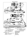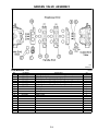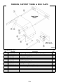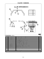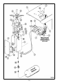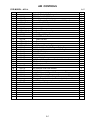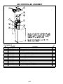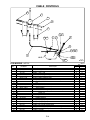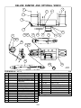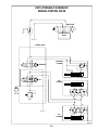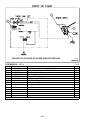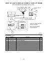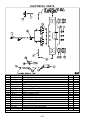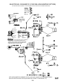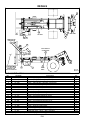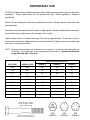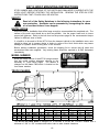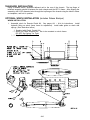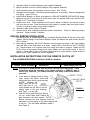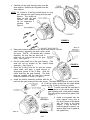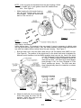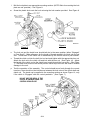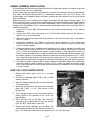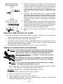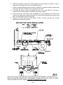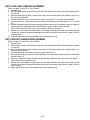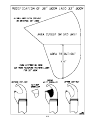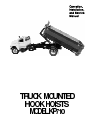
1
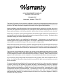
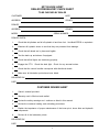
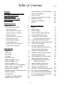
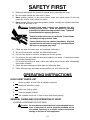
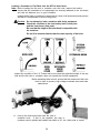
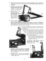
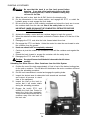
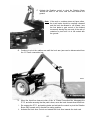
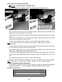
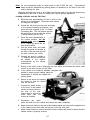
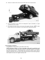
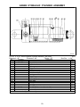
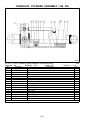
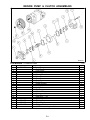
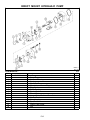
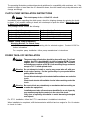
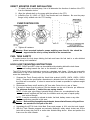
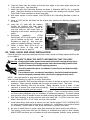
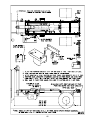
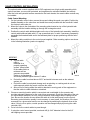
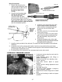
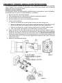
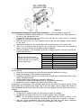
Operation,
Installation,
and Service
Manual
A note to our customers, parts managers and dealers:
This manual has been prepared to assist you in the proper use, daily care, and operation of
your new K--PAC equipment. It contains specific information on the many built--in features
of your equipment, the accessories and options that are available, general specifications, and
instructions for making minor adjustments.
Read this manual carefully before operating your K--PAC equipment, and keep it in a
convenient location for later reference.
In order to ensure that you have the most current owner’s manual available for your
equipment, we have added a revision code to each manual. Please note the information
listed below and specify when placing service calls or ordering parts.
Manual for Model: KP710
This manual covers models beginning with Serial #: 2000
Manual #: 9710--1
Rev.:
ISSUED TO:
ISSUED BY:
Owner’s Name
Krause Dealer
Mailing Address
City
City
State
State
Date of Purchase
Warranty
K--PAC EQUIPMENT DIVISION OF
KRAUSE CORPORATION
P.O. BOX 2707
Hutchinson, Kansas 67504--2707
The Krause Corporation (herein referred to as Krause), Hutchinson, Kansas expressly warrants each new
product manufactured by it to be free from defects in materials and workmanship under normal use for
a period of 365 days from date of shipment from Krause, to the original retail purchaser.
Krause’s obligation under this warranty is limited to repairing and/or replacing, at its option, any part or
parts within the applicable warranty period, as set out above, which shall be returned by the owner or any
Krause authorized dealer to the factory, and which shall disclose to Krause’s satisfaction to be defective.
Krause may, at its option, elect to grant adjustments in the field through an authorized representative and
may thereby elect to waive the requirement that parts be returned to Krause’s factory. All claims shall be
processed through your Krause authorized dealer.
A new warranty period is not established for replacements. Replacements are warranted for the
remaining portion of the original warranty period. The repair or replacement of defective parts under this
warranty will be made without charge to the owner except for transportation.
Krause does not warranty electric motors, hydraulic pumps and cylinders, accessories and other parts not
manufactured by Krause, but supplied with or as a part of Krause products. Krause will, however, obtain
and pass on any adjustments provided by the manufacturers of such parts under these manufacturer’s
warranties.
The provisions of this warranty do not apply to any product or parts which have been subject to misuse,
negligence or accident, or which have been repaired or altered outside of Krause’s factory in any way so
as in the judgement of Krause to affect adversely its performance or reliability. Neither does this warranty
apply to normal maintenance service and parts, or to normal deterioration due to wear and exposure.
Any service part sold by Krause shall be warranted for thirty (30) days from date of shipment from our
factory. No credit for labor will be allowed under this warranty if the part, upon our inspection, proves to
be non--defective.
To the extent allowed by applicable law, this warranty is expressly in lieu of other warranties, expressed
or implied, in fact or by law, including any implied warranty of merchantability of fitness for a particular
purpose. The remedies of repair or replacement as set forth are the only remedies under this warranty.
Krause disclaims any obligations or liability for loss of time, inconvenience, commercial loss or direct
consequential, special or incidental damages. This warranty is in lieu of any other obligation or liability
of Krause of any nature whatsoever by reason of the manufacture, sale, lease or use of such products
and Krause neither assumes, nor authorizes anyone to assume for it, any other obligation or liability in
connection with such products.
KP710 HOOK HOIST
DEALER PREDELIVERY CHECK SHEET
TO BE CHECKED BY DEALER
CUSTOMER
DATE
ADDRESS
COUNTY
DEALER
ADDRESS
COUNTY
MODEL
SERIAL NUMBER
DEALER CHECK:
1.
Check that all cylinders are full of hydraulic oil and free of air. Use Mobil DTE25 or equivalent.
2.
Examine all hydraulic hoses to see that they are protected from damage.
3.
Check that all decals are in place and legible.
4.
Test the back--up and alarms if equipped.
5.
Check that all tail lights are functioning properly.
6.
Engage the P.T.O. Check the dash light. Check for any unusual noises.
7.
Check that the control handles correspond with directional decals.
8.
Make sure all lubrication points have been lubed.
DELIVERED BY:
DATE
CUSTOMER REVIEW SHEET
1.
Owner’s manual provided.
2.
Warranty card is filled out and mailed.
3.
Review the safety warnings and cautions as listed in this manual.
4.
Review the container loading, and unloading procedures.
5.
Explain the importance of proper maintenance of the boom pivot, boom slide and hydraulic
components.
6.
Review all of the lubrication points.
DELIVERED BY:
DATE
1
Table of Contents
WARRANTY
Rev.2/08
DELUXE BUMPER w/ OPTIONAL WINCH
P20
DEALER PREDELIVERY CHECK SHEET
1
HYDRAULIC SCHEMATIC
P21
CUSTOMER REVIEW SHEET
1
HOIST UP LIGHT
P22
TABLE OF CONTENTS
2
HOIST--UP LIGHT & BACK--UP ALARM
P23
HOOK HOIST SPECIFICATIONS
3
ELECTRICAL PARTS
P24
SAFETY DECALS
4
ELECTRICAL SCHEMATIC
P25
DECALS
P26
OPERATING SECTION
SAFETY FIRST
O1
OPERATING INSTRUCTIONS
O1
SAFETY
A1
Hook Hoist Check List
O1
INSTALLATION
A1
General Guidelines for Operation
O1
MODEL NUMBER
A1
Loading A Container or Flat Rack
O1
TRUCK CHASSIS, SPECIFICATIONS
A1
Dumping A Container
O4
CLUTCH PUMP INSTALLATION
A2
Unloading Flat Rack or Container
O4
Winch Operation (Option)
O6
Flat Rack Operation (Option)
O6
POWER TAKE--OFF INSTALLATION
A2
Flat Rack Specifications
O6
DIRECT MOUNTED PUMP INSTALLATION
A3
Loading a Vehicle onto a Flat Rack
O7
FUEL TANK ADJUSTMENT
A3
K--PAC Warranty Information
O8
HOOK HOIST MOUNTING
A3
OIL TANK, VALVE AND HOSE INSTALL.
A4
INSTALLATION SECTION
Fanbelt Clutch Pump Installation
Mounting Bracket For Clutch Pump
PARTS SECTION
A2
A2
CABLE CONTROL INSTALLATION
A6
TOOL BOX
P1
HYDRAULIC PRESSURE GAUGE
A7
HYDRAULICS
P3
PNEUMATIC CONTROL INSTALLATION
A8
MAIN FRAME
P5
TAILBOARD INSTALLATION
A10
FLAT RACK
P6
DELUXE BUMPER w/OPTIONAL WINCH
A10
HYDRAULIC TANK
P7
DELUXE BUMPER INSTALLATION
A11
GREEN CYLINDER 5 x 49--3/4
P8
GREEN CYLINDER 3 x 35
P9
INSTALLATION INSTRUCTIONS FOR
REMOTE CLUTCH KIT
A11
GREEN CYLINDER 3 x 48
P10
WIRING HARNESS INSTALLATION
A15
MUNCIE PUMP & CLUTCH ASSEMBLIES
P11
HOIST UP LIGHT INSTALLATION
A15
DIRECT MOUNT HYDRAULIC PUMP
P12
HYDRAULIC SYSTEM START--UP
A16
GRESEN VALVE ASSEMBLY
P13
REFLECTIVE TAPE INSTALLATION SHEET
A17
FENDERS, SUPPORT TUBES, MUD FLAPS
P14
KP710 PAD & SHIM REPLACEMENT
A18
PLASTIC FENDERS
P15
KP710 BOOM CYLINDER REPLACEMENT
A18
AIR CONTROLS
P17
36” TO 33” BOOM INSTRUCTION SHEET
A19
AIR CONTROL TOWER ASSEMBLY
P18
9710--SUB ILLUSTRATION
A21
REMOTE VALVE & CONTROLS
P19
2
SPECIFICATIONS
Chassis C.A.:
Frame Width:
G.V.W.:
Frame Height:
Frame:
Load Rating:
Dump Angle:
Operating Pressure:
Gear Pump:
Operation:
Hook Height:
SPECIFICATIONS AND FEATURES INCLUDE:
Rev.7/21/00
33”, 36”, 54” (108/120 CA)
Weight: 2,650 lbs.
Hydraulic Planetary: 4 ton or 6 ton 50’ of 7/16” cable w/hook,
level wind feature
Cylinders: Twin double acting 5 x 50 Cylinder
3 x 35 Boom Cylinder (108/120/138 CA)
3 x 48 Boom Cylinder (156 CA)
Low Pressure American S.A.E Hydraulic System
Gear driven hydraulic pump
Braided and socked hose
Phenolic pads in boom
Sliding “L” arm
2 Container Locks
Gravity lock on hook
108”, 120”, 138”, 156”
34” (Outside) + reinforcement thickness
33,000lbs. Min.
To 40” top of chassis
“Lo-- Pro” recommended (108/120 CA)
Full length 3” w x 6”h square tube
20,000 lbs. with suitable G.V.W.
including body weight
50_ with suitable body length
3000 PSI
23 gpm @ 1500 rpm direct mount STD.
In-- cab controls standard
54”, 62” (138/156 CA)
3
SAFETY DECALS
See Parts Listing page for part number and proper location.
4
SAFETY FIRST
A. Read and understand this operator’s manual before operating the hoist.
B. Be sure safety decals are clean and in place.
C. Never position yourself, or any other person, under any raised portion of the hoist
unless the hoist is firmly resting on blocks.
D. Never operate this unit unless the hydraulic system, including the cylinders and lines,
are full of oil and free of air.
Warning: Escaping fluid under pressure can penetrate the skin
causing serious injury. Avoid the hazard by relieving
pressure before disconnecting hydraulic lines. Tighten all
connections before applying pressure.
Search for leaks with a piece of cardboard. Protect hands
and body from high pressure fluids.
If an accident occurs, see a doctor immediately. Any fluid
injected into the skin must be surgically removed within a
few hours or gangrene may result.
E.
F.
G.
H.
Check the area for power lines and overhead obstructions.
Be sure the area and container are clear of personnel.
Do not load, dump or unload a container on uneven ground.
Do not move the truck while the hoist and container are raised. A raised load creates
a top heavy unstable load.
I. Do not use any method to hold a valve open which will not let the valve automatically
close when released.
J. Check the pivot bushing and slide pads for excessive wear.
K. Check all snap rings and shaft securing bolts to be sure they are tight.
OPERATING INSTRUCTIONS
HOOK HOIST CHECK LIST
A.
Check hydraulic oil level with all cylinders retracted.
B.
Grease all lubrication points.
C.
Rollers are free to rotate.
D.
Tires are properly inflated.
E.
The container hook lock is free to move and works properly.
GENERAL GUIDELINES FOR OPERATION OF HOIST
LOADING A CONTAINER OR FLAT RACK
Caution: Be sure the area in which the hoist is to be operated is level,
clear of personnel, as well as obstacles overhead and on
the ground. Operating on a unlevel surface could cause
damage to the load or hoist equipment.
O1
Loading a Container or Flat Rack onto the KP710 Hook Hoist
Note: Before loading the flat rack or container onto the hoist, inspect the load to
ensure that the materials to be transported are securely fastened to the tie--downs
and that all fasteners are in good condition.
Inspect the flat rack or container to ensure that it is clear of all obstructions and persons
and that it is not fastened or stuck to the ground.
Caution: Do not attempt to load a container with faulty equipment.
Check the condition of the hook safety latch, boom pivot
and the inner boom slide pads.
Be sure that the height of the hoist hook is compatible with
the container.
Do not lift a container heavier than the rated capacity of the hoist.
Inspect the condition of the “A” Frame and be sure that the combined weight of the pay
load and the flat rack or container does not exceed the 20,000# equipment.
Before activating either control, ensure that the area around the hook
hoist is clear of persons, high voltage overhead wires and other
obstructions.
M9710-- 5
A. Line up the hoist truck boom with the rack or
container hook. If this is not possible, the rack or
container can be picked and loaded from within a 30_ arc, either side of center.
O2
B. Engage the parking brake, depress the clutch and engage the P.T.O. Activate the
In--Cab Control to slide the Hook Arm back to the fully retracted position (this is very
important).
C. Activate the In--Cab Control to
pivot the Rotation Boom from
the back of the cab to the
container “A” Frame height
position behind the truck.
D. Disengage the P.T.O. and
brake and back--up
the truck until the
hook jaw engages
the “A” Frame bar.
Stop the vehicle,
set the brake and
engage the P.T.O.
M9710-- 6
E. Push the rotation
control forward
to move the Rotation Boom forward until the bottom of the rack or container is
approximately 10 inches above the guide rollers at the back of the truck. The operator
may be required to release the brake so that the truck can be steered until the guide
rollers align with the sills of the rack or container.
F. If the sills on the bottom of the rack or container are not
in line with the guide rollers and the truck, the operator
must reposition.
G. When the sills and rollers line up continue to activate
the control to move the rack or container onto the hoist
frame. By releasing the brake and allowing the
truck to roll back under the load, dragging the
rear end of the rack or container along the
ground can be minimized.
H. Continue the loading procedure until the
rack or container is off the ground and
re--apply the brake to eliminate further
movement of the truck.
The Rotation Control should be activated
until the sills of the rack or
container are in full contact
with the hoist frame.
M9710-- 7
I. Activate the Hook Arm Control to extend the
Hook Arm which will pull the rack or container
towards the back of the truck cab to engage the
rack or container sills with the four safety locks
on the hoist frame.
J. Disengage the P.T.O. Observe road and weather
conditions and drive with the caution required for
a vehicle under load.
M9710-- 8
O3
DUMPING A CONTAINER
Caution: Be sure that the truck is on firm level ground before
dumping. If one side of the load breaks loose in this high
center of gravity position, a truck on unstable footing may
roll over on its side.
A. When the path is clear, back the K--PAC Hoist to the dumping site.
B. Put the transmission in the neutral position, and engage the P.T.O. or switch the
hydraulic pump on and engage the truck brake.
C. Be sure that the path is clear including overhead and retract the hook arm to move
the container back from the cab and free of the safety locks on the frame.
IMPORTANT: INNER BOOM MUST BE COMPLETELY RETRACTED BEFORE
RAISING THE HOIST.
D. Activate the rotation control until the container begins to touch the ground.
E. When the material has been dumped, activate the Rotation Boom to lift the bin off the
ground.
F. Disengage the P.T.O. and drive the hoist forward about three feet.
G. Re--engage the P.T.O. and brake. Active the control to rotate the arm forward to raise
the container from the ground.
H. Hook arm should still be completely retracted.
I. Continue to pivot the rotation arm towards the cab until the container rests against the
frame.
J. Extend the hook forward to engage the container with the safety locks.
K. Disengage the P.T.O. and drive safely.
Caution: Do not pull forward until the hoist is lowered to the full--down
position.
Unloading Flat Racks Bins or Other Containers from the Hoist System
A. Position the rear of the truck approximately 10 feet in front of the desired resting place
for the rack or container. This will allow for the distance the rack or container will travel
during the unloading procedure.
B. Put the truck transmission in neutral and engage the parking brake.
C. Inspect the desired area for obstruction both around and overhead
and instruct all persons to stand
clear of the equipment.
D. Inspect the load on the truck to
ensure that it will remain stable
during the unloading procedure.
E. Engage the truck’s P.T.O. and
activate the Hook Arm Control to
retract the Hook Arm completely.
This procedure will push the rack or
container away from the back of
the truck cab.
M9710-- 8
O4
F. Activate the Rotation control to pivot the Rotation Boom
toward the back of the truck, until the load touches the
ground.
Note: If the rack or container does not have rollers,
the truck brake should be carefully released
and the truck be allowed to roll forward, (use
the foot brake to gain control of the forward
movement) leaving the rear end of the rack of
container to pivot until it is in full contact with
the ground.
M9710-- 7
G. Continue to pivot the rotation arm until the hook arm jaws can be disconnected from
the “A” Frame connection bar.
M9710-- 9
H. When the Hook Arm Jaws are clear of the “A” Frame Connection Bar, disengage the
P.T.O. and after ensuring that the path is clear, move the truck forward about three feet.
I. Re--engage the P.T.O. and parking brake and activate the control to pivot the Rotation
Boom fully forward until it reaches its resting position.
J. Activate the Hook Arm Control and extend the Hook Arm towards the truck cab.
O5
Winch Operation (Optional Equipment)
Caution: Set brake before operating winch.
The winch controls are located at the rear of the truck, on the driver side.
M9710-- 11
M9710-- 10
There are two levers; the top lever operates the winch under power and the bottom lever
operates the free wheel control on the winch.
To operate the winch in the free wheel mode, raise the lever and position it into the second
notch.
To lock the free wheel lever in the free wheel position, lower the lever until the second
notch rests in the bottom of the key hole.
The winch cable can then be pulled out to the desired length without restraint.
Note: The cable should never be pulled out beyond a single wrap of cable on
the drum.
The winch can be returned to the power position by lifting the free wheel lever and pulling
it out so that the first notch locks into the key hole.
To power the winch cable in or out, be sure that the free wheel lever is locked in the first
notch before activating the winch power control lever.
To retract the cable hydraulically, pull the power control lever towards the front of the truck.
To extend the cable hydraulically, push the power control lever towards the rear of the
truck.
The cable will stop when the control is in the neutral position.
Read the winch manufacturer’s instructions for more information on the winch operation.
Note: Never jam any of the Hoist Hydraulic Controls into the operating position.
Flat Rack Operation (Optional Equipment)
The optional K--PAC flat rack can be used to transport a variety of materials and equipment
including automobiles. It can be equipped with stake pockets and head board.
Flat Rack Specifications
Length . . . . . . . . . . . . . . . . . . . . . . . . . . . . . . . . . . . . . . . 17--1/2 feet
Width . . . . . . . . . . . . . . . . . . . . . . . . . . . . . . . . . . . . . . . . . . 92 inches
Weight . . . . . . . . . . . . . . . . . . . . . . . . . . . . . . . . . . . . . . . . . 2,080 lbs.
Maximum deck load . . . . . . . . . . . . . . . . . . . . . . . . . . . . . 7,000 lbs.
O6
Note: Do not concentrate loads on small areas of the K--PAC flat rack. Concentrated
loads should be distributed by placing planks of hardwood on the deck of the rack
before placing the load.
Magnetic tail lights may need to be installed on the rear end of the flat rack when being
transported on the hoist in order to comply with vehicle lighting regulations.
Loading a Vehicle onto the Flat Rack
A. Back the hoist approximately 20 feet in front of the
vehicle to be transported. Disconnect and remove
the magnetic tail lights.
M9710-- 12
B. Unload the flat rack from the hoist according
to the normal unloading procedures, and
leave the hook engaged to the “A” Frame
Connecting Bar. This will ensure that the
flat rack does not move while the vehicle
is being loaded onto the rack.
C. Place the truck’s transmission in
the neutral position, set the
parking brake and engage the
P.T.O. Place the winch into the
free wheel position.
D. Pull the winch hook and cable
through the guide slot located at
the front of the rack and out until
the hook reaches the vehicle.
E. Connect the hook to a bridle or
“V” Strap so that the vehicle can
be loaded in the manner
recommended by the vehicle
manufacturer.
F. Return to the winch control, disengage the free wheel and activate the winch cable
control to put minor tension on the cable.
G. If the vehicle to be loaded is disabled, straighten the
wheels to ensure proper loading, place the
transmission in neutral and release the
parking brake.
H. Return to the winch and operate
the control to load the vehicle
onto the flat rack.
I. Connect two safety chains
to the front of the loaded
vehicle and secure them to
the front of the rack,
making sure to remove as
much slack from the
chains as possible.
M9710-- 13
J. Disconnect
the
winch
cable and hook from the vehicle and retract the cable completely.
K. Attach two more chains to the rear of the loaded vehicle and connect the opposite end
of the chains to the chain slots on the rear of the flat rack deck.
L. Attach chain binders to remove the slack from the chains and check to ensure that the
loaded vehicle is properly secured.
O7
M. Continue to load the flat rack onto the K--PAC hoist in the normal manner.
M9710-- 14
N. Put the transmission of the vehicle to be transported in park (if automatic) or in gear
(if manual) and set its brake.
O. Re--examine the safety chains and reconnect the magnetic tail lights. NOTE: Amber
beacon lights may be necessary in some states when transporting vehicles.
M9710-- 15
K--PAC Warranty Information
Congratulations on the purchase of the KP710 Hook Hoist.
K--PAC Equipment, Division of Krause Corporation, takes pride in engineering and
manufacturing products which are of the finest quality and highest standard. As a result,
we stand behind any K--PAC Equipment product or component claimed to be defective
during the warranty period. To avoid delays with the service process, please read the
warranty instructions (in the first section of this manual) at the time of the vehicle purchase;
and complete and return the supplied warranty card.
O8
THE FOLLOWING ILLUSTRATED PARTS SECTION HAS BEEN
COMPILED TO REFLECT PART NUMBERS REQUIRED TO ORDER
PARTS, AND TO SUPPORT THE INSTALLATION SECTION FOR
DIMENSIONS AND DESCRIPTIONS OF ALL PARTS, BOLTS, PINS,
ETC.
THE OPERATOR CAN ALSO IDENTIFY PART NAMES TO
CLARIFY PROPER OPERATIONAL STEPS.
TOOL BOX
FOR MODELS -- KP710
Item
1
2
3
4
5
6
6/97
Part Number
9606--111--0
82--245
9606--112--0
62--708
63--110
64--110
Part Description
Left Tank Strap Weldment
Steel Tool Box
Right Tank Strap Weldment
5/8NC x 2--1/2” GD.8 Cap Screw
5/8NC Lock Nut
5/8” STD. Flat Washer
P1
Qty.
1
1
1
4
4
4
P2
FOR MODEL - KP710
Item
1
2
3
4
5
6
7
8
9
10
11
12
13
14
15
16
17
18
19
20
21
22
23
24
25
26
27
28
29
30
31
32
33
34
35
36
37
38
39
40
41
42
43
44
45
46
47
48
49
Part Number
47483
47773
47848
47109
47772
47484
46680
46305
45714
45303
4594
C2377
C2253
47798
17287
C5480
C6071
C2270
47842
47841
47108
62285
62286
47840
49631
47133
47796
47111
C4498
47785
45740
47147
47797
47781
47766
47780
15463
46395
47777
45712
47765
C1057
C5511
C2282
C0075
45289
18552
45522
45734
47776
C0930
0342
HYDRAULICS -- MODEL KP710
Part Description
1/2” x 65”(JIC) 3000 PSI Hose Assembly
37_ Flare Male Coupler Hydraulic Fitting
1/2” x 82” Hydraulic Tube Assembly
3/4(M)JIC to 3/4(F)JIC 90_ Swivel Hydraulic Fitting
37_(M) Bulkhead Tee Hydraulic Fitting
1/2” x 30” (JIC) 3000 PSI Hose Assembly
O--Ring 37_ Flare 90_ Ell Hydraulic Fitting
5” x 49--3/4” (#600--3244) Hydraulic Cylinder Assembly
3” x 35” Hydraulic Cylinder Assembly
3” x 48” Hydraulic Cylinder Assembly
3/4(M) O--Ring to 3/4(M) JIC Adapter Hydraulic Fitting
3/4NPT (F) Pipe Tee Hydraulic Fitting
3/4--14 Pipe Close Nipple Hydraulic Fitting
3/4NPT(M) to 3/4 Hose Straight Hydraulic Fitting
1NPT to 3/4NPT Hex Reducer Hydraulic Fitting
3/4ID x 155” Suction Hose
Hose Clamp (1--3/16” to 1--3/8”)
1/2NPT(M) to 3/4 Hose End Hydraulic Fitting
3/4(M) O--Ring to 1/2NPT(F) 90_ Hydraulic Fitting
Valve SD4--1(SV) -- 2BSLD--SAE
9/16(M) O--Ring to 3/4(M) JIC Hydraulic Fitting
1/2” x 162” JIC Black 2W Hose Assembly
1/2” x 24” JIC 90_ Black 2W Hose Assembly
3/4(M) JIC to 7/8(M) O--Ring 90_ Hydraulic Fitting
9,000 # Winch (30--282 Series)
12,000 # Winch (30--286 Series)
3/4” x 18” Low Pressure Hose
7/8(M) O--Ring to 3/4 (M) JIC Adapter Hydraulic Fitting
1--1/16 O--Ring to 1--1/16 JIC Hydraulic Fitting
SP Control Valve V20 (Reversed w/ Free Flow Spool)
Power Beyond Sleeve SAE #10 (V20 Valve)
1--1/16 O--Ring to 1--1/16 JIC 90_ Hydraulic Fitting
1--1/16(M) to 3/4NPT (F) 90_ Hydraulic Fitting
3/4” x 60” JIC 3000 PSI Hose Assembly
1--1/16(M) JIC to 1NPT (M) Hydraulic Fitting
Gear Pump (P20A396QUYL20--65)
Sight Gauge w/ Temp 5”
Hydraulic Tank Weldment
3/4NPT Magnetic Plug
Oil Strainer -- 25 GPM
1--1/4NPT(M) to 1--1/4NPT(F) 90_ Hydraulic Fitting
1--1/4NPT Close Nipple Hydraulic Fitting
1--1/4NPT(F) x 1--1/4NPT Ball Valve
1--1/4NPT(M) to 1--1/4 Hose Hydraulic Fitting
Hose Clamp (T--Bolt Type)
1--1/4ID x 69” 100R4 Hose Assembly
Filler Cap Assembly
In--Tank Filter
Filter Element (Long)
Hose Clamp -- 1/2”O.D.
5/16NC x 3” GD5 Cap Screw
5/16NC Nylon--Top Lock Nut
P3
2/07
Qty.
4
4
2
3
2
6
5
2
1
1
2
1
1
3
1
1
4
1
1
1
2
1
2
2
1
1
1
5
1
1
1
1
1
1
1
1
1
1
1
1
1
1
1
2
2
1
1
1
1
3
3
3
P4
MAIN FRAME
FOR MODELS -- ALL
Item
Part Number
2/07
Part Description
Qty.
Item
31
32
1
2
3
60-- 701
64-- 146
9610-- 355-- 0
9606-- 15-- 0
5/32”DIA. x 1-- 1/4” Cotter Pin
5/8” SAE Flat Washer
Lock Plate Weldment (54”, 62”)
Hook Lock Weldment (36”)
1
2
1
1
4
5
6
7
8
D
60-- 270
82-- 242
64-- 162
62-- 300
9610-- 136-- 0
9610-- 54-- 0A
5/8”DIA. x 3” Clevis Pin
Shock Pad
1/2” SAE Flat Washer
1/2NC x 1” GD5 Cap Screw
36” Inner Boom Weldment
54” Inner Boom Weldment
1
1
1
1
1
1
D
9610-- 62-- 0A
62” Inner Boom Weldment
1
K
9610-- 354-- 0A
54” Inner Boom Weldment
1
K
9610-- 362-- 0A
62” Inner Boom Weldment
1
lH
62-- 718
9610-- 120-- 5A
9610-- 00-- 10
9610-- 00-- 14
3/8NC x 1”Flat Head Allen Bolt
Inner Boom Pad (Large)
Shim, .06 Thick
Shim, .12 Thick
6
1
2
2
12
13
14
9610-- 00-- 12
99-- 197
23-- 721
23-- 722
Rod Pin - Extend Cylinder
1-- 1/4” DIA. Retaining Ring
3” x 35” Hydraulic Cylinder
3” x 48” Hydraulic Cylinder
1
2
1
1
15
16
17
9610-- 120-- 7
99-- 201
9610-- 620-- 0
9610-- 638-- 0
Cylinder Pin - Extend Cylinder
1” DIA. Retaining Ring
Outer Boom Weldment (120)
Outer Boom Weldment
1
2
1
1
18
19
65-- 113
9610-- 26-- 0A
1/4NF Zerk
Rod End Pin Weldment - Lift
Cylinder
3
2
20
21
22
64-- 108
64-- 107
62-- 420
1/2” STD. Flat Washer
1/2” STD. Lock Washer
1/2NC x 1-- 1/4” GD5 Cap
Screw
5
5
5
23-- 703
64-- 165
62-- 803
64-- 103
9610-- 00-- 4
9610-- 00-- 3
5” x 49-- 3/4” Hydraulic Cylinder
3/8” SAE Flat Washer
3/8NC x 7/8” GD5 Cap Screw
3/8” STD. Lock Washer
1/8” Shim - Pad Retainer
1/16” Shim - Pad Retainer
2
8
8
8
2
2
9710-- 0-- 9
9610-- 120-- 2A
9610-- 00-- 8
9610-- 00-- 15
Pad Retainer
Outer Boom Pad
Shim, .06 Thick
Shim, .10 Thick
2
2
2
2
9
10
11
D
H
H
H
K
23
24
25
26
27
H
lH
H
H
H
28
29
30
H
H
H
H
Part Number
Part Description
Qty.
9610-- 120-- 3A
9610-- 538-- 0
Inner Boom Pad (Small)
Frame Extension Weldment
(138)
2
1
9610-- 556-- 0
Frame Extension Weldment
(156)
1
33
9610-- 28-- 0A
Base End Pin Weldment - Lift
Cylinder
2
34
35
36
37
63-- 134
65-- 101
9274-- 415-- 3
62-- 123
3/8NC Nylon-- Top Lock Nut
1/8” STD. Zerk
Bolt Collar - Roller
3/8NC x 3-- 1/2” GD5 Cap
Screw
2
2
2
2
38
64-- 154
3-- 1/8” x 2-- 1/8” x 10 Ga.
Machine Bushing
2
39
40
41
42
9274-- 412-- 0
9610-- 520-- 0
9610-- 27-- 0
64-- 199
Outside Roller
Main Frame Weldment
Main Pivot Shaft Weldment
3” x 2” x 10 Ga. Machine
Bushing
2
1
1
4
43
44
45
46
47
48
49
64-- 109
9606-- 108-- 10
9606-- 108-- 9
9606-- 105-- 0
9606-- 108-- 8
63-- 108
62-- 351
5/8” STD. Lock Washer
Special Bolt
Retainer Washer
Guide Roller Assembly
Roller Shaft
1/2NC Nylon-- Top Lock Nut
1/2NC x 4-- 1/2” GD5 Cap
Screw
2
2
2
2
1
1
1
50
51
52
53
54
55
9606-- 208-- 15A
9606-- 208-- 22
62-- 395
64-- 108
63-- 107
9610-- 80-- 0
Lock Plate (KP706)
Hold Down Spacer (KP706)
1/2NC x 6” GD5 Cap Screw
1/2” STD. Flat Washer
1/2NC Lock Nut
Rt. Hold Down Weldment
(KP710)
2
2
4
4 /8
4 /8
1
56
9610-- 81-- 0
Lt. Hold Down Weldment
(KP710)
1
57
58
59
62-- 351
9710-- 0-- 15
99-- 221
1/2NC x 4-- 1/2”GD5 Cap Screw
Boom Rest
Loctite (use on l items)
8
1
H
H
D
K
H
P5
108/120 CA Models
138/156 CA Models
Included in 9710--84--0 Pad & Shim Kit
FLAT RACK
FOR MODELS -- KP710
Item
1
2
3
4
5
6
7
8
9
Part Number
9606--45--4A
53--152
9606--45--5
99--200
9602--3--0
9602--2--0A
60--217
64--113
60--724
4/02
Part Description
Roller
Flanged Wear Bushing (3/4” O.D. x 5/8” I.D.)
Roller Pin
Retainer Ring -- 5/8”
ICC Slider Tube Weldment
ICC Bumper Weldment
3/4” DIA. x 5” Clevis Pin
3/4” STD. Flat Washer
1/8” DIA. x 1--1/4” Cotter Pin
P6
Qty.
1
2
1
2
3
3
9
12
9
HYDRAULIC TANK ASSEMBLY
FOR MODELS -- KP710
Item
1
2
3
4
5
6
7
8
9
10
11
12
Part Number
9610--35--0
25--235
25--215
64--148
62--763
25--2375
25--1184
25--1190
75--137
25--233
75--161
25--2374
9/01
Part Description
Hydraulic Tank Weldment
Sight Gauge w/ Temp. 5”
Filler Cap Assembly
5/16” STD. Lock Washer
5/16NC x 1” Socket Head Cap Screw
In--Tank Filter (TIF08--025--G)
1NPT to 3/4NPT Reducer Hydraulic Fitting
3/4(M)NPT to 3/4(F)NPT Service Tee Hydraulic Fitting
3/4NPT Pipe Plug
Oil Strainer (25 GPM)
1--1/4NPT Square Head Black Pipe Plug
3/4NPT Magnetic Plug
P7
Qty.
1
1
1
2
2
1
1
1
2
1
1
1
HYDRAULIC CYLINDER ASSEMBLY
23--703 5” x 49--3/4” Hydraulic Cylinder Assembly (LIFT)
Retracted -- 60”
Extended -- 109--3/4”
Stroke -- 49--3/4”
Item
1
2
3
4
5
6
7
8
9
10
11
12
13
14
15
16
17
18
19
20
Part Number
25--2433
K
K
K
K
K
K
K
K
D
D
23--804
Part Description
Manufacturer’s Label
Counterbalance Valve
Full Locknut
Wear Ring
Piston Seal
Piston
O--Ring
Rod Assembly
Barrel Assembly
Sleeve
Wear Ring
O--Ring
Back--up Washer
Rod Seal
Lock Wire
Rod Wiper
Washer
Cap Screw
Lock Washer
Steel O--Ring Plug
Seal Kit ( K Items Included in Kit)
Not Included in Cylinder Assembly
P8
4/00
Rod Dia. -- 2--1/2”
Qty.
1
2
1
2
1
1
1
1
1
1
2
1
1
1
1
1
1
2
2
3
GREEN HYDRAULIC CYLINDER ASSEMBLY
Rev.9/01
23--721 3” x 35” Green Hydraulic Cylinder Assembly (EXTEND)
Retracted -- 45”
Extended -- 80”
Stroke -- 35”
Item
1
2
3
4
5
6
7
8
9
10
11
12
13
14
15
16
Part Number
25--2433
K
K
K
K
K
K
K
D
D
23--803
Part Description
Manufacturer’s Label
Counterbalance Valve
Full Locknut
Piston
Piston Seal
O--Ring
Barrel Assembly
Rod Assembly
Head
Wear Ring
O--Ring
Back--up Washer
Lock Wire
Rod Seal
Rod Wiper
Steel Plug (not shown)
Seal Kit ( K Items Included in Kit)
Not Included in Cylinder Assembly
P9
9/01
Rod Dia. -- 1--3/4”
Qty.
1
2
1
1
1
1
1
1
1
1
1
1
1
1
1
1
HYDRAULIC CYLINDER ASSEMBLY (156 CA)
Rev.9/01
23--722 3” x 48” Hydraulic Cylinder Assembly (BOOM EXTEND)
Retracted -- 58”
Extended -- 106”
Stroke -- 48”
Item
1
2
3
4
5
6
7
8
9
10
11
12
13
14
15
Part Number
25--2433
K
K
K
K
K
K
K
D
D
23--803
Part Description
Manufacturer’s Label
Counterbalance Valve
Full Locknut
Piston
Piston Seal
O--Ring
Barrel Assembly
Rod Assembly
Head
Wear Ring
O--Ring
Back--up Washer
Rod Seal
Rod Wiper
Steel Plug (not shown)
Seal Kit ( K Items Included in Kit)
Not Included in Cylinder Assembly
P10
9/01
Rod Dia. -- 1--3/4”
Qty.
1
2
1
1
1
1
1
1
1
2
1
1
1
1
1
MUNCIE PUMP & CLUTCH ASSEMBLIES
M9305--23
FOR MODELS -- H SERIES PUMP
Item
1
2
3
4
5
6
7
8
9
10
11
12
13
14
15
16
17
18
19
20
21
Part Number
25--2139
25--2165
25--2166
25--2167
7/00
Part Description
H Series Pump
Shaft Seal
Front Cover
Bushings
Balance Seal
Wear Plate
Gear Set
Body Seal
Dowel Pins
Pump Housing
Rear Cover
Lock Washer
Cap Screw
Woodruff Key
Nut
Snap Ring
Pipe Plug -- 3/4
Pipe Plug -- 1--1/4
Clutch
Coil -- Clutch
Pulley -- Clutch
1/2NF Hex Locking Jam Nut
P11
Qty.
1
1
4
2
2
1
2
4
1
1
4
4
1
1
1
1
1
1
1
1
1
DIRECT MOUNT HYDRAULIC PUMP
M9610--7
Rev.1/99
FOR MODELS Item
1
2
3
4
5
6
7
8
9
10
11
12
13
14
15
16
Part Number
25--2391
6/97
Part Description
Gear Pump
Snap Ring
Outboard Bearing
Seal
Shaft End Cover
Check Assemblies or Plug
Ring Seals
Roller Bearings
Pocket Seals
Thrust Plates
Integral Drive Shaft and Gear Set
Gasket Seals
Gear Housing
Port End Cover
Washer
Stud or Cap Screw
Nut
P12
Qty.
1
GRESEN VALVE ASSEMBLY
7/00
M9706--21
FOR MODELS -- ALL
Item
1
2
3
4
5
6
7
8
9
10
Part Number
25--2495
25--2409
25--2413
25--2508
25--2408
25--2502
25--2412
25--2411
11/00
Part Description
Gresen V20 2 Spool Valve Assembly (Reversed)
Main Relief Valve
Relief Valve Seal Kit (WH Std. Relief)
Valve Section -- 4 Way, 3 Position, Free Flow Spool (Reversed)
Valve Section Seal Kit
Valve Section -- 4 Way, 3 Position Spool (Reversed)
Outlet Cover
Hex Nut
Lock Washer
Studs
Inlet Cover
P13
Qty.
1
1
1
1
1 / Section
1
1
6
6
3
1
FENDERS, SUPPORT TUBES & MUD FLAPS
Match Drill (4)
Holes .562 DIA.
M9706--22
Rev.3/01
FOR MODELS - ALL
Item
1
2
3
4
5
6
7
8
9
Part Number
9305--55--0A
9305--57--0A
9305--56--0
62--503
63--106
44--129
62--108
9274--0--1
63--134
9610--0--13
4/01
Part Description
Standard Fender Weldment -- (Width = 25--1/2”)
Narrow Fender Weldment -- (Width = 22--1/4”)
Fender Support Weldment
1/2NC x 1--1/2” Set Screw
1/2NC Hex Nut
Mud Flap
3/8NC x 1” GD.5 Cap Screw
Mud Flap Backing Plate
3/8NC Self Locking Nut
Fender Mounting Bracket (Optional)
P14
Qty.
1
1
2
2
2
1
4
1
4
Spec.
PLASTIC FENDERS
FOR MODELS -- KP710
Item
Part Number
1
2
3
4
5
6
7
8
9
10
K
2/07
44--190
44--188
82--255
K
K
K
K
44--220
9724--0--1
62--367
63--140
Part Description
Set of Plastic Fenders -- 52”
Set of Plastic Fenders -- 44”
Mounting Kit for 44--190
5/16NC x 1” Hex Head Cap Screw
5/16” STD. Flat Washer
5/16NC Nylon--Top Lock Nut
5/16NC x 1--1/4” Carrier Bolt
Ironman Mud Flap (24” x 24”)
Mud Flap Backing Plate
3/8NC x 3/4” Hex Flange Serrated Bolt
3/8NC Hex Flange Serrated Nut
Items Included in 82--255 Mounting Kit
P15
Qty.
1
1
16
23
23
7
2
2
8
8
Rev. 10/04
M9200-- 86
P16
AIR CONTROLS
FOR MODEL -- KP710
Item
1
2
3
4
5
6
7
8
9
10
11
12
13
14
15
16
17
18
19
20
21
22
23
24
25
26
27
28
29
30
31
32
33
2/07
Part Number
62--394
63--167
25--2495
9610--45--0
82--315
82--124
9274--196--0
9274--196--2
62--530
64--100
63--100
9274--196--3
9274--196--4
9274--196--1
62--342
62--115
64--104
64--103
63--102
82--157
62--485
64--158
64--170
63--151
82--313
82--314
82--163
82--167
74--478
Part Description
Qty.
Hydraulic Tank -- 20 Gallon
5/16NC x 2--1/2” GD5 Cap Screw
5/16NC Nylon Lock Nut
Control Valve -- 2 Spool V20 (Reversed Wiff Spool)
Handle Kit -- V20 Valve
Air Actuator Assembly
1
3
3
1
2
2
Air Line -- 80’
Air Control Tower Assembly
Tower
1/4NC x 1/2” Cap Screw
1/4” STD. Lock Washer
1/4NC Hex Nut
Cover
Cap
Air Control Mounting Plate
1/4NC x 3/4” Hex Washer Thread Cutting Screw
3/8NC x 1--1/2” Hex Washer Thread Cutting Screw
3/8” STD. Flat Washer
3/8” STD. Lock Washer
3/8NC Hex Nut
Joystick Controller
#10NC x 1/2” Cross Recess Pan Head Machine Screw
P.T.O. Indicator Light
Air Valve
#10 Flat Washer
#10 External Tooth Lock Washer
#10 Hex Nut
1/8NPT Male -- 1/4” Tube 90_ Compression Fitting
1/4” Tube Quick Lock Tee
3/8NPT Male -- 1/4” Tube Straight Compression Fitting
Pressure Protection Valve (customer supplied)
1/4NPT Hex Nipple
Decal -- Important Operation Instructions
1
1
14
14
14
1
1
1
4
4
4
4
4
1
4
1
1
4
4
4
1
1
1
1
1
1
P17
AIR CONTROLLER ASSEMBLY
FOR MODELS - ALL
Item
1
2
3
4
5
6
7
2/07
Part Number
Part Description
82--341
Tower Cover (Stainless Steel)
79--579
LED Lamp (Includes retaining clip)
82--313
Elbow, Swivel
82--314
Tee, Swivel
82--124
Air Line 1/4od SAE J844 Type “A”
82--346
Connector, Swivel
82--332
Pneumatic Controller, 2--Section
82--333
Pneumatic Controller, 3--Section
8
74--636
Decals, Controls
9
82--343
Clear Cap
82--339
O--Ring (between sections)
82--344
Conversion Kit from 2 To 3 Sections
82--345
Conversion Kit To Electric PTO Switch
Doubled Quantities Reflect 2--Sections / 3 SectionsK
P18
Qty.
1
2
2
1
Spec.
4/6K
1
1
1
2/3K
2/4K
CABLE CONTROLS
15
1
2
16
17
6
18 19
4
7
8
5
10
9 10 11
3
10 12
VALVE
13 14
FOR MODELS -- KP710
Item
Part Number
1
2
3
82--238
9274--0--1305
72--132
72--131
72--109
9610--0--17
9610--0--23
72--108
4
5
6
7
D
D
D
8
K
K
H
H
H
H
K
K
9
10
11
12
13
14
15
16
17
18
19
9610--45--0
9610--108--1
25--2505
25--2199
25--2201
62--106
62--839
63--141
62--115
62--420
63--107
Rev. 4/07
M9706-- 23
10/07
Part Description
Controller
Control Mount
Cable -- 108” Long
Cable -- 156” Long
Cable -- 252” Long
Control Cable Bulkhead Plate
Control Cable Bulhead Plate
Clevis Kit (Includes ONE each of D Items)
Clevis w/ 3/8” Hold
Pin
Cotter Pin
Handle Kit (Includes K Items)
Valve Handle
V--20 Valve Linkage Kit (Includes H Items)
Link
Cotter Pin
Link Plate
Pin
Handle Bracket
Screw
1/4NC x 4” GD5 Cap Screw
1/4NC x 6” GD5 Cap Screw
1/4NC Hex Flange Serrated Nut
3/8NC x 1--1/2” Hex Washer Thread Cutting Screw
1/2NC x 1--1/4” GD5 Cap Screw
1/2NC Lock Nut
P19
Qty.
2 spool 3 spool
2
2
2
2
2
1
0
2
3
2
3
3
3
0
1
3
2
3
3
0
3
3
2
2
0
3
3
3
2
2
DELUXE BUMPER AND OPTIONAL WINCH
4
7
6
5
3
2
1
8
16 15
17
14
13
12
11
10
9
18 19
20
21 22
24
25
23
Rev.2/08
M9606-- 34
FOR MODELS -- KP710
Item
1
2
3
4
5
6
7
8
9
10
11
12
13
14
15
Part Number
9606-- 47-- 0
82-- 254
9606-- 45-- 1
62-- 342
62-- 103
See page P3
9606-- 45-- 2
99-- 200
64-- 200
9606-- 45-- 4A
9606-- 45-- 6
53-- 152
9606-- 45-- 5
82-- 298
62-- 118
Part Description
Winch Control
Knob - 1/2NC Threads
Cover Plate - Left
1/4NC x 3/4” Hex Washer Thread
Cutting Screw
1/4NC x 2” GD5 Cap Screw
Winch Control Valve
Cover Plate - Right
Retainer Ring - 5/8”
1”OD x 5/8”ID x 1/16” Bushing
Roller
Threaded Rod
Flanged Bushing 3/4”OD x 5/8”ID
Roller Pin
Yoke Kit - 5/16UNF Threads
3/8NC x 2-- 1/2”GD5 Cap Screw
Qty.
1
1
1
8
2
1
1
4
4
2
1
4
2
2
1
Item
16
17
18
19
Part Number
63-- 134
82-- 251
82-- 249
82-- 250
20
21
22
23
24
25
K
K
K
P20
2/08
Part Description
Qty.
3/8NC Nylon-- Top Lock Nut
1
Tensioner Wire Rope Kit 10”Drum 1
9,000# Winch
1
12,000# Winch
1
Remote Clutch Assembly (see
82-- 263
1
pages A11-- A14)
62-- 432
5/16NC x 1”GD5 Cap Screw
2
63-- 167
5/16NC Nylon-- Top Lock Nut
2
9606-- 46-- 0A Bumper Shell Weldment
1
9606-- 48-- 0
Clutch Rod Weldment
1
82-- 252
Cable w/ Hook
1
Supplied with Clutch Control Kit
KP710 HYDRAULIC SCHEMATIC
MANUAL CONTROL VALVE
WINCH VALVE
WINCH
CONTROL VALVE
A
EXTENSION
CYLINDER
B
EXTENSION
A
B
A
B
LIFT
LIFT
CYLINDER
B
A
B
A
LIFT
CYLINDER
REV.10/07
M9710-- 1
P21
HOIST UP LIGHT
USE WITH 79-250 BACK-UP ALARM (SINGLE FUNCTION)
FOR MODELS - KP710
Item
1
2
3
4
5
6
K
2/07
Part Number
K
79--580
79--269
79--581
9716--0--30
79--248
62--422
63--141
Rev.2/08
Part Description
Hoist Up Light (Requires 3/4” DIA Hole)
Hoist Up Light (Requires 7/8” DIA Hole)
Pigtail, 16”
Bracket -- Safety Switch
Remote Switch
1/4NC x 1--1/4” GD5 Cap Screw
1/4NC Hex Flange Serrated Nut
Current
P22
Qty.
1
1
2
1
1
3
3
HOIST UP LIGHT & BACK--UP ALARM w/ HOIST--UP ALARM
HOIST UP LIGHT AND BACK UP ALARM WITH HOIST UP ALARM
4
3
5
6
7
PLUGS INTO BACK UP
CIRCUIT
8
POS
NEG
-
POS
BATTERY
+
-
WBL
+
FUSE
2
PLUGS INTO GROUND CIRCUIT
RED
HOIST UP LIGHT
IN DASH
COLORED
WHITE
TRUCK CAB
+
NEG
BLACK
HOIST UP LIGHT
IN AIR CONTROL TOWER
CLIP BULLET CONNECTORS FROM
PIGTAIL AS NECESSARY
HOIST
UP
PTO
ENGAGED
HOIST UP LIGHTS IN CAB ARE
POLARITY SENSITIVE
PTO ON
PTO OFF
1
REV 2/08
M9710--29
FOR MODELS -- KP710
Item
1
2
3
4
5
6
7
8
2/07
Part Number
79--580
79--581
9716--0--30
62--422
63--141
79--248
79--610
79--606
Part Description
Hoist Up Light (for 3/4” DIA hole)
Pigtail, 192”
Switch Mounting Plate
1/4NC x 1--1/4” GD5 Cap Screw
1/4NC Hex Flange Serrated Nut
Remote Switch
Back--Up Alarm, Dual Function
Pigtail, 21”
P23
Qty.
1
3
1
3
3
1
1
3
ELECTRICAL PARTS
Item
Part Number
Part Description
1
79--591
Main Wiring Harness
2
79--592
Rear Sill Wiring Harness
3
79--593
Rear I.D. Harness
4
79--594
2--Conductor Harness
5
79--580
LED Lamp, Red
6
79--589
Grommet, For 2” Round Lamp
7
79--584
Led Lamp, 2” Round, Red
8
79--590
Grommet, For Oval Lamp
9
79--613
LED Lamp, Oval, S/T/T
10
79--611
Back--Up Lamp, Oval
11
79--491
License Plate Bracket & Lamp
12
79--606
Pigtail, 21”
13
79--581
Pigtail, 192”
14
79--610
Back--Up Alarm, Dual Function
15
9716--0--30
Switch Mounting Plate
16
79--248
Remote Switch
17
62--422
1/4NC x 1--1/4” GD5 Cap Screw
18
63--141
1/4NC Hex Flange Serrated Nut
* Items not included with tailboard (no bumper)
P24
Qty.
0
0
0
1
1
0
0
0
0
0
1
3
3
1
1
1
3
3
Bumper*
1
1
1
3
5
3
3
4
2
2
ELECTRICAL SCHEMATIC (FOR DELUXE BUMPER OPTION)
LED LAMPS ARE POLARITY SENSITIVE. IF A LAMP DOES NOT FUNCTION, SWITCH BULLET TERMINAL CONNECTIONS.
GROUND
AUXILIARY
LEFT TURN
STOP (5-- Wire)
RIGHT TURN
TAIL
BACK-- UP
HARNESS
GREEN (RIGHT)
YELLOW (LEFT)
DUMMY
PLUGS
DO NOT REMOVE
DUMMY PLUGS IF
TERMINAL IS NOT
UTILIZED.
RED
BROWN
WHITE
DETAIL B
(Left & Right Sides)
BLUE
BROWN
GREEN
YELLOW
WHITE
RED
DETAIL A
BLACK
HARNESS
WHITE /
BLACK /
YELLOW /
/
RED
GREEN /
BROWN /
/
BLUE
FUNCTION
GROUND
AUXILIARY
LEFT TURN
STOP (5-- Wire)
RIGHT TURN
TAIL
BACK-- UP
REMOVE DUMMY PLUGS FROM FEMALE BULLET TERMINALS
AS NECESSARY. DO NOT REMOVE DUMMY PLUGS IF
TERMINAL IS NOT UTILIZED. AUXILIARY FUNCTION CAN
BE UTILIZED TO ADD WORK LIGHTS IF DESIRED OR IN
CONNECTING HOIST-UP / BACK-UP ALARM.
NOTE: WHEN CONNECTING HARNESSES, PIGTAILS, AND LAMPS, CONNECT PER LIKE NUMBERS SHOWN
ABOVE AS WIRE COLORS MAY DIFFER (BLACK WIRE MAY CONNECT TO BROWN WIRE, ETC.)
P25
DECALS
DANGER
STAND CLEAR!
12
XX,000 LBS
MODEL
SERIAL
XX,000 LBS
18
IMPORTANT
14
REAR VIEW
15
WARNING
TOP VIEW
74 - 596
3
VIEW THROUGH
CAB WINDOW
2
16
17
1
8
BOTH SIDES OF
OUTER BOOM
9
10
6
ON CAB AT
11 EYE
LEVEL
WARNING
DANGER
STAND CLEAR!
WARNING
3 4 5 13 14
INSIDE OF CAB
NEXT TO CONTROLS
6
7
12
BOTH
SIDES
FOR MODELS - KP710
Item
1
2
3
4
5
6
7
8
9
10
11
12
13
14
15
16
17
18
K
Rev. 7/07
M9710-- 20
10/07
Part Number
Part Description
Decal Kit (Includes D Items Below)
9710--50--0
D 74--485
Decal -- DANGER Powerlines (Hooklift)
D 74--482
Decal -- CAUTION Inner Boom
D 74--478
Decal -- IMPORTANT Operation Instructions
D 74--486
Decal -- WARNING Align Container
D 74--297
Decal -- WARNING Uneven Ground
D 74--276
Decal -- WARNING Hydraulic Safety
D 74--627
Decal -- Iron Man
D 74--648
Decal -- Krause Trademark
D 74--490
Decal -- DANGER Hook Height Must Match
D 74--512
Decal -- K--Pac Patent
D 74--477
Decal -- CAUTION Operate on Level
D 74--302
Decal -- DANGER Stand Clear
D 74--542
Decal -- Hoist Up
D 74--481
Decal -- CAUTION Do Not Drive PTO
D 74--476
Decal -- CAUTION Set Brake
D 74--483
Decal -- Winch Instructions
D 74--596
Decal -- Warning, Stand Clear
D 74--491
Decal -- 20,000 Lbs.
K 74--600
Reflective Tape -- Red/White (NOT SHOWN)
K 74--601
Reflective Tape -- White (NOT SHOWN)
Specify exact quantity needed. See page A16 for suggested locations on truck frame
P26
Qty.
1
1
2
1
1
3
1
2
1
1
1
3
1
2
1
1
1
2
20 Ft.
4 Ft.
PROPER BOLT USE
DO NOT use these values if a different torque value or tightening procedure is given for a specific
application. Torque values listed are for general use only. Check tightness of fasteners
periodically.
Shear bolts are designed to fail under predetermined loads. Always replace shear bolts with
identical grade.
Fasteners should be replaced with the same or higher grade. If higher grade fasteners are used,
these should only be tightened to the strength of the original.
Tighten plastic insert or crimped steel--type lock nuts to approximately 110 percent of the dry
torque shown in the chart, applied to the nut, not to the bolt head. Tighten toothed or serrated--type
lock nuts to the full torque value.
NOTE: “Lubricated” means coated with a lubricant such as engine oil, or fasteners with phosphate and
oil coatings. “Dry” means plain or zinc plated without any lubrication. Tighten lubricated bolts
to approximately 80% of dry bolts.
BLACK OR PLATED BOLTS
BOLT SIZE
WRENCH SIZE
GRADE 2
GRADE 5
GRADE 8
3/8”
9/16”
20
33
45
7/16”
5/8”
32
52
70
1/2”
3/4”
50
80
105
5/8”
15/16”
100
150
210
3/4”
1--1/8”
160
260
375
7/8”
1--5/16”
175
415
600
1”
1--1/2”
250
625
880
1--1/8”
1--11/16”
375
850
1400
1--1/4”
1--7/8”
530
1100
1765
1--1/2”
2--1/4”
930
1400
2540
KP710 HOIST MOUNTING INSTRUCTIONS
STUDY NAMES AND LOCATIONS OF THE PARTS AND FAMILIARIZE YOURSELF WITH THE
HOOK HOIST BEFORE STARTING THE INSTALLATION. READING THE STEP--BY--STEP
INSTRUCTIONS THAT FOLLOW WILL BE HELPFUL.
SAFETY
Read all of the Safety Notations in the following instructions for your
own protection. Accidents can be prevented by recognizing the cause
of an accident before it can happen.
INSTALLATION
Select an area for installation that will be large enough to accommodate the completed unit. The
surface of the work area should be as level as possible. Use the proper hand tools to insure
proper bolt tightness. Refer to the bolt chart on the previous page for the recommended torque
values for different sizes of bolts.
If a forklift is to be used to lift the KP710 from the transport vehicle to the installation area, care
should be taken not to engage chains or hooks to areas of the Hook Hoist which may cause
damage to hydraulic hoses or any parts of the structure.
Before starting installation procedures, check the shipping list to ensure that all parts and
accessories have been supplied. Any missing items should be reported to K--PAC equipment
immediately.
MODEL NUMBER
Know the model number of the KP710 being mounted.
Use this model number whenever referring to the
assembly or parts listing pages. The number is
stamped on the Name Plate which is located on the
front frame member.
TRUCK CHASSIS
A
B
C
D
E
F
108“
120“
138“
156”
38”
38”
38”
38”
40”
40”
40”
40”
146”
158”
177.75”
193.75”
124.62”
136.62”
156.81”
174.81”
11”
11”
11”
11”
36” boom
28”
28”
N/A
N/A
G
54” boom
15”
15”
21”
21”
62” boom
NA
NA
14”
14”
36” boom
35.5”
35.5”
N/A
N/A
H
54” boom
53”
53”
53”
53”
Rev.5/06
62” boom
NA
NA
60.5”
60.5”
The KP710--120 Hook Hoist is designed for a minimum of 33,000 lbs. G.V.W.R. chassis with a
minimum of 108” to 156” unobstructed behind cab--to--axle chassis clearance.
A1
The preceding illustration provides dimensional guidelines for compatibility with containers, etc. If the
chassis is higher or lower than the 40” dimension shown, then the lowest hook pickup dimension will
change accordingly.
CLUTCH PUMP INSTALLATION INSTRUCTIONS
Danger:
This clutch pump is for a 12 Volt D.C. circuit.
Immediately upon unpacking the clutch pump, check for shipping damage by spinning the clutch
by hand. If any metallic rubbing is heard, do not attempt to repair the clutch. Return the clutch
to Muncie for replacement.
This package should contain the following:
1
1
1
2
2
------
Clutch Pump
12 Foot Length of Wire
Rocker Switch & Light
Ring Terminals
Star Washers
3
2
1
2
1
------
Sta--Kon Terminals
Butt Splice
Switch Mounting Bracket
Screws, Lockwashers & Nuts
In--Line Fuse
Fanbelt Clutch Pump Installation
Mounting Bracket For Clutch Pump
K--PAC has clutch pump engine mounting kits for selected engines. Contact K--PAC for
further information.
For complete pump installation follow pump manufacturer’s instructions.
POWER TAKE--OFF INSTALLATION
Caution: The power take--off selection should be done with care. For diesel
engines, the P.T.O. should be 85% to 100% of engine R.P.M. For gas
engines, the P.T.O. should be 65% to 80% of engine R.P.M. The direct
mounted pump requires a SAE B 2--bolt mounting flange and must
accept a 7/8” 13 tooth splined shaft.
Warning: Do not attempt to install or service any power take--off with your
truck engine running. Put the ignition keys in your pocket before
getting under the truck.
Do not allow truck engine to be started while workmen are under the
truck.
Block truck wheels with suitable chocks before working under the
truck.
Warning: Be sure to block any raised body or mechanism before working on
or under the equipment.
Installed power take--offs must never be shifted in or out of gear by
any means except by the controls in the cab of the truck.
Stay clear of spinning driveshafts to avoid becoming entangled
and injured.
For P.T.O. installation, follow the P.T.O. manufacturer’s installation instructions.
When installation is completed, refill the transmission with fluid and run engine for 5 to 10 minutes
to check for leaks.
A2
DIRECT MOUNTED PUMP INSTALLATION
1. To install a direct mounted pump, first of all determine the direction of rotation of the PTO
from the illustration below.
2. Align the splined shaft on the pump with the splines in the PTO.
3. Install the four (2) 1/2NC x 2” GD.5 Cap Screws and Lock Washers. Be sure the pump
flange is fully seated onto the PTO housing.
PUMP POSITION FOR:
M9305--46
M9610--19
Rev.7/99
4. Tighten all hardware.
Warning: Direct mounted hydraulic pumps weighing more than 50 Lbs. should be
supported at the rear by a strap attached to the transmission.
FUEL TANK SAFETY
If needed remove the fuel straps holding fuel tank and lower the fuel tank to a safe shielded
position during hoist installation.
HOOK HOIST MOUNTING INSTRUCTIONS
NOTE: RIGHT and LEFT sides can be established by standing behind the truck frame
and looking towards the front or the direction of travel.
The KP710 Hook Hoist is designed to mount on a standard truck frame. If there are unmovable
obstructions on top of the truck frame, you must add spacers to raise the hoist frame to clear, or
move the obstructions.
1. Compare the Truck Chassis with the Hook Hoist ordered (108CA, 120CA, 138CA, 156CA
Hoist). Compare the specification dimensions to determine how far forward on the chassis
the Hoist can be mounted. It is best to mount as far forward as possible for optimum weight
distribution.
2. Recommended frame cutoff would be 38” from axle Center--Line to rear of frame.
3. If chassis is longer than the above CA’s the chassis can be cut off shorter per difference.
The minimum would be 1” behind the rear spring shackle.
NOTE: If bolts, pipe, pipe fittings, hydraulic fittings, hoses, etc., are substituted for the
hardware supplied with the hoist, the installer must use parts of equal quality
and service strength.
NOTE: It may be necessary to relocate air tanks, fuel tank, battery cases or any other
accessories mounted in this area.
Caution: Before drilling through the truck chassis, be sure that all hoses, wiring and lines
are moved out of the path of the drill.
4. Unpackage the KP710 Hook Hoist Main Frame and prepare to lift it onto the truck chassis.
5. With the Truck Chassis prepared as previously illustrated, safely attach chains and lift the
hoist with a heavy duty fork lift or some other suitable lifting device. Move and position the
frame over the truck chassis.
A3
6. Lower the frame onto the chassis so that the back angle on the frame aligns with the end
of the truck frame. See illustration.
7. Attach the 9610--00--2 Mounting Brackets as shown in illustration (M9710--19) on opposite
page. Reposition Brackets as necessary to not interfere with existing truck brackets. Install
Front Roller Frame extension as shown and weld.
8. With frame square on truck chassis, weld TEN 9610--00--2 Mounting Brackets in place on
frame.
9. Using a 17/32” drill bit, drill holes into the chassis rails matching the Mounting Brackets on
the frame.
10. Insert the 1/2” bolts with flat washers
through the brackets and truck frame,
install lock washers and nuts. Tighten all
nuts and bolts per bolt torque chart at
beginning of this section, matching the bolt
grade.
11. Hold--down
installation:
KP706
Hold--downs, KP710 Hold--downs, or both
can be installed on this unit. Install per
illustration on page A5. Also see parts
pages for hardware callouts if needed.
12. Install a Boom Rest (9710--0--15) as
shown in photo at right weld per
instructions shown on page P4.
OIL TANK, VALVE AND HOSE INSTALLATION
M9710-- 26
Clean all hydraulic components and keep all hoses, tubes, valves and fittings capped until they are
to be installed.
BE SURE TO READ THE SAFETY INFORMATION THAT FOLLOWS!
Warning: Escaping fluid under pressure can penetrate the skin causing serious injury.
Avoid the hazard by relieving pressure before disconnecting hydraulic lines.
Tighten all connections before applying pressure.
Search for leaks with a piece of cardboard. Protect hands and body from high
pressure fluids.
If an accident occurs, see a doctor immediately. Any fluid injected into the skin
must be surgically removed within a few hours or gangrene may result.
NOTE: Use pipe sealant on pipe thread joints ONLY.
Refer to parts drawing on page P2 for steps listed below.
1. Attach the Hydraulic Tank mounting brackets to the side of the tank as shown in the following
illustration. Align mounting brackets with top edge and ends of tank. Tack weld.
2. Mount Tank Assembly onto truck as shown. Watch clearance on top of hoist. If more
clearance is desired, then lower tank accordingly. Check for adequate clearance between
bottom of tank assembly and the ground.
3. Clamp Tank Assembly to truck frame in desired position. Check mounting bracket location
on frame leaving adequate room for installation of cables and plumbing. If present location
does not work, move to suitable location and weld mounting brackets to tank as shown above.
4. With Tank Assembly in position desired, mark and match drill 11/16”Dia. holes into frame.
Attach Tank with 5/8” x 2--1/2” Bolts and lock nuts provided.
5. Install valve fittings and hoses as shown (on Parts Section pages P2--P3 “HYDRAULICS”)
for routing proper valve bank and function to cylinder, etc. Install sleeve over bundle of hoses
for protection. Route hoses to clear sharp obstructions to protect from wear.
6. Be sure to install hoses on proper valve bank because the valve sections are different.
7. The routing of the hoses from the Lift Cylinders to bulkhead tees must be done carefully.
MAKE SURE that hoses are not twisted and will have adequate flexibility during operation.
A4
A5
VALVE CONTROL INSTALLATION
The optional cable controls supplied with K--PAC equipment are a high--quality assembly which
seal out moisture, are corrosion protected, and engineered to minimize backlash (lost motion).
After the hoist and hydraulic tank are mounted to the truck chassis, the remote cable controls may
be installed.
Cable Control Mounting:
1. On the hydraulic control valve, remove the screws holding the spool cover plate. Position the
handle assembly on the valve face and install the screws provided with the handle kit. Install
the clevis pin and cotter pin.
2. Mount the valve to the underside of the mounting plate located on top of the hydraulic tank
assembly with the handles sticking up through the rectangular cutout.
3. Position the control cable bulkhead plate on the top of the hydraulic tank assembly. Install the
control cable bulkhead plate with 1/2” cap screws and nuts, or weld. If necessary, temporarily
assemble the threaded cable end to the bulkhead plate for proper positioning with the valve
handles.
4. Mount the cable controllers to the control mount supplied. Other mounting options are shown
in the following illustration (parts not supplied).
IMPORTANT:
a. A good cable
path is
essential for a
properly operating
system. Keep bends
in the cable path to a
minimum and as
generous as possible.
Under no circumstances
M9200-- 35
should any bend be tighter than an 8” radius.
b. Protect the cable from heat above 225_F and avoid hot areas such as the exhaust
system, etc.
c. Protect the cable from physical damage such as pinching or crushing and do not use
cable supports which may crush or deform the cable.
d. Allow room for flexing where the cable is attached to moving parts of the equipment so
that the cable is neither kinked nor stretched.
5. Choose a mounting location which is convenient and comfortable for the operator and
provides adequate clearance for the control lever movement. Check the underside of the cab
for reinforcement members, air lines, wiring harnesses, and linkages before cutting into the
floor. Be sure the location chosen allows the cable to be led easily away from the control.
Reversing control direction usually is not necessary. In most cases, the direction of the lever
movement for a given valve function can be changed by switching the hydraulic lines at the
valve. If this is not an option, control operation can be changed simply by turning the cable
controller 180_.
6. Cut a hole for the control cables to pass through.
7. If using the control mount provided, mark and drill (4) .343” diameter holes for the 3/8”
self--tapping screws provided.
A6
Cable Connections
1. Remove the screw from the
cable controller where the cable
end will install. Do NOT remove
the other screws passing
through the cable control
housing.
2. Screw the hex threaded cable
end into the cable controller
end. Moving the cable
controller handle will allow
easier access to start the thread. If
the hex threaded cable end is not visible,
make certain the cable is free to slide back
and forth and shake the cable end with the
end in the downward position.
M9200--36
3. Install the control head end of the cable
into the cable controller. Reinstall the
cable controller screw passing through
the groove in the end of the cable
housing.
4. Check the control for free movement and
correct valve control.
5. To connect the cable to the valve handle,
start by removing the mounting nut from
the cable assembly. (Large nut in the
photo above)
6. Install the threaded portion of the cable
assembly through the bulkhead weldment
and replace the mounting nut.
7. Install the clevis provided to the cable end. The cable end should be parallel to the bulkhead
weldment.
8. Locate the clevis on the control valve handle. If a hole is not provided in the control valve
handle for the clevis, drill a .375” diameter hole through the valve handle as illustrated. Install
pin and keeper included with clevis.
9. Do a final check of the controls for free movement and correct valve control.
HYDRAULIC PRESSURE GAUGE
M9706-- 33
A7
1. Locate and remove plug from port used for
pressure gauge.
2. Install Pressure Gauge with fittings or
adapters as needed.
3. Remove Acorn Nut from adjusting screw.
4. Loosen Jam Nut.
5. Using allen wrench, adjust to proper
pressure.
6. Tighten Jam Nut, holding adjustment screw
in position.
7. Re--install Acorn Nut.
8. Test unit for proper operation, re--adjust to
correct pressure if needed.
9. Remove test Pressure Gauge and re--install
plug.
10. Re--test unit checking for leaks and proper
operation.
PNEUMATIC CONTROL INSTALLATION INSTRUCTIONS
The optional pneumatic controller provided with K--PAC equipment are dual three--way regulating
valves. Output of the controllers is proportional to the control lever position and is balanced
against the force of an internal spring.
Pneumatic Actuator Installation
The pneumatic actuator has been partially assembled and pre--lubricated for ease of installation.
The actuator does not have to be disassembled for installation.
1. Remove the valve if previously installed.
2. Find a suitable area free of dust and dirt to attach the pneumatic actuators.
3. Set the hydraulic valve on its mounting base.
4. Determine which spools are to be pneumatically controlled.
5. From the valve assembly:
a. Remove and discard the original retainer screws and valve spring cover.
b. Retain the handle end of the spool. Remove and discard the 5/16” shoulder bolt from
the end of the valve spool exposed by the removal of the valve spring cover.
c. Remove and discard the original centering spring and two original centering cups.
d. Insure the original seal retainer on the valve spool is properly seated.
6. Apply a small bead of removable thread lock to the threads of the spool adapter (item 1).
Holding the spool on the opposing end, hand tighten the assembly using a flat screwdriver
through the rear fitting port into the end of the piston (item 12). DO NOT USE AN AIR GUN.
7. Secure the actuator assembly to the valve body using the four (4) socket head cap screws and
lock washers (items 4 & 7). Test for proper alignment by turning the valve spool. The spool
should rotate freely.
8. Mount the valve and install fittings.
M9806--7
M9806--7
A8
M9806--8
Pre--Assembled Pneumatic Control Tower Installation ---- See Parts Section page P18
1. Determine a suitable location which is in a comfortable location for the driver and not in
the way of the transmission lever.
2. Position the lower bolt holes so that the bolts will miss any cable, wires or structural
members in or under the cab floor.
3. Mark and drill the four (4) .343” diameter holes for the 3/8” self--tapping screws supplied
for the tower.
4. Determine a location in the area between the mounting holes to run the air lines.
5. Drill a 2” to 3” diameter hole through the floor of the truck. Remove all burrs and sharp
edges. Line the hole with the grommet material supplied.
6. Using the washers on the underside of the floor, attach the tower to the floor with the 3/8”
screws and lock nuts.
Silver:
Blue:
Green:
Orange:
Yellow:
Red:
Black:
Silver:
White:
After the control tower has been
mounted, the air lines can be routed.
The air line tubing is color coded as
shown in table at right:
Supply
Winch / Cable In
Winch / Cable Out
Hoist Raise / On
Hoist Raise / Off
PTO
Exhaust
Auxiliary In
Auxiliary Out
To remove an air line from a fitting, push the line in, hold the internal sleeve of the fitting then pull
the air line out.
1. Pass the air lines through the hole lined with grommet material in the floor.
2. Route the exhaust air line outside of the truck cab.
3. Determine a suitable route for the air lines to the control valve. Avoid sharp bends, sharp
edges, and heat sources.
4. Install supplied elbow fittings into pneumatic actuators.
5. Connect the air lines to the elbow fittings in the pneumatic actuators.
6. Bundle the air lines together and secure out of harm’s way.
A decal with an assortment of .94” diameter labels are provided with the owner’s manual. These
decal labels can be applied to the under side of the clear plastic caps to identify the function of
each pneumatic control handle. After the decals have been applied, snap the clear covers into the
handles.
Start--up Procedure
1. Charge the air system of the truck and check all lines for leakage.
2. Operate the controllers and check for correct hydraulic valve movement.
NOTE: The controllers pressurize the port toward which the handle is moved. If the
function is to be reversed, exchange the air lines at the controller or actuator.
3. After the correct connections have been made, and the hoist has been completely
installed, engage the P.T.O. to check out the operation of the hoist.
A9
TAILBOARD INSTALLATION
Using a suitable device, assemble tailboard unit to the rear of the chassis. The top flange of
tailboard assembly should fit between the truck chassis and the KP710 frame. After aligning the
assembly, drill 21/32” diameter holes through the top flange of the chassis using the holes in frame
as templates, and bolt in position.
OPTIONAL WINCH INSTALLATION (includes Deluxe Bumper)
WINCH INSTALLATION
1. Assemble winch for Remote Clutch Kit. See pages A11 -- A14 for instructions. Install
hydraulic fitting on winch (leave loose for adjustment). Install cable guide on winch with
springs. (See illustration below)
* Supplied with Clutch Control Kit.
* * Spring on Cable Tensioner Kit. Ear to be mounted on winch frame.
DO NOT Get Spring Too Tight.
* * * Supplied with Winch.
A10
2.
3.
4.
5.
6.
7.
8.
9.
10.
Assemble Winch to Deluxe Bumper using supplied hardware.
Mount hydraulic control to Deluxe Bumper using supplied hardware.
Route hydraulic lines from hydraulic control to winch. (See P2--P3)
Assemble control linkage. Test fit and adjust linkage prior to mounting. Remove linkage after
test--fitting. (see A13--A14)
Install Deluxe Bumper w/ Winch as explained in DELUXE BUMPER INSTALLATION below.
Mark and cut hole in truck frame for winch control rods as required. Make sure rods DO NOT
DRAG or HIT truck frame or bumper.
Install control rods. Check adjustment from test fit (adjust if needed), and secure in place
with lock nuts on rods. Route hoses along truck frame to hydraulic tank from winch control.
Connect to hydraulic system using fittings supplied.
Assemble cable guide rollers to bumper.
Operate winch after completing hydraulic system connections. Check for leaks and proper
operation. Adjust controls if required.
DELUXE BUMPER INSTALLATION
1. Using a floor jack or suitable lifting device, assemble Deluxe Bumper to the rear of the truck
chassis, (the top flange of the Deluxe Bumper should fit between the truck chassis and the
KP710 frame).
2. After aligning assembly, drill 21/32” diameter holes through top flange of the truck chassis
using the hole of the hoist frame as a guide. Install bolts in holes but DO NOT TIGHTEN
yet. Adjust bumper so it is square with truck frame and clamp in position. Match drill SIX
21/32” holes in side plates through truck frame (Make sure area behind holes is clear of
objects.) Install bolts in holes just drilled, adjust bumper to proper position, tighten bolts the
proper specs, check bumper for correct alignment.
INSTALLATION INSTRUCTIONS FOR THE REMOTE CLUTCH KIT
Fits all WARN INDUSTRIAL 9,000 and 12,000 lb. winches.
Items Included in this Kit
1. Remote Clutch Assembly
2. Instructions
3. Replacement parts list
NOTE: It is easier to install the kit with the winch removed from the vehicle. These
illustrations show the assembly of the remote clutch to a SERIES 9 and 12
winch only; therefore, you should carefully read these instructions before
you start.
a. If the winch is equipped with a safety
latch, remove the socket head bolts
holding the latch onto the gear housing.
(NOTE:
Although the
safety latch will not be
used with this kit, you
must reinstall the two bolts to fill the
tapped holes in the gear housing.)
See Figure 1 to the right.
b. With the winch lying horizontal, remove
the ten socket head bolts holding the
gear housing to the drum support. (NOTE:
Before removing the gear housing, mark the
placement of the housing on the drum support with
a felt pen. This will make installation easier.)
See Figure 2.
A11
FIGURE 1.
M9606--37
c. Carefully pull the gear housing away from the
drum support. Remove the old gasket from the
drum support.
NOTE: On 12,000 lb. (5,400 kg) models there is a ring
gear between the gear housing and the drum
support. This should be
taken off with the gear
housing and should
not be separated if
possible.
See
Figure 2.
FIGURE 2.
M9606--38
d. Remove the detent assembly or the clutch shaft retainer from the
gear housing, depending on which winch model
you have. (NOTE: On Models with a detent
assembly, be sure that the steel ball is
taken out, so it will not fall into the gear
train.) See Figure 3.
e. Pull the clutch shaft out of the gear housing. (This
shaft will not be needed for the remote clutch
FIGURE 3.
assembly.) See Figure 3.
f. Place the O--Ring from the kit onto the remote
clutch shaft, and apply a small amount of
all--purpose grease to the O--Ring. Slide the
clutch shaft into the gear housing. The shaft
must be installed with the stop pins oriented
toward the detent as shown in Figure 4.
M9606--39
g. Install the detent assembly provided with the kit,
back into the gear housing in the order shown. The large detent spacer is used for 9,000
lb. (4,100 kg) winch models and the small detent
spacer for the 12,000 lb (5,400 kg) models.
NOTE: To make sure that the steel ball is
in the groove of the clutch shaft, tilt the
gear housing back a little while installing.
This will help the steel ball into place.) See
Figure 4.
M9606--40
FIGURE 4.
A12
h. Install a new gasket onto the
drum support, being sure to
line up the holes of the gasket
with the holes in the drum
support. It may be easier to
hold the gasket in place if you
apply a slight coat of grease to
the gasket face.
NOTE: If the ring gear was separated from the gear housing (12,000
lb. models only) a new gasket should be installed there
also. See Figure 5.
i. While keeping the felt marks lined up,
bolt the gear housing back onto the
drum support. Torque the socket head
bolts to 100--120 Lb.--in.
M9606--41
Figure 5.
NOTE:
The gear housing
may need to be lined--up
before bolting down. For housing to line--up properly, it may be necessary to slightly rotate
the ring gear inside the gear housing. Also, the detent assembly can be temporarily removed,
but must be installed before bolting down the gear housing. See Figure 5.
j. Bolt the clutch lever onto the clutch shaft using a 3/8” flat washer and 3/8NC hex nut.
(See Figure 6) The position of the clutch lever on the clutch shaft may be adjusted for
different control locations, but the WARN supplied decal can only be used if the clutch
is in the “Engaged” position with the control pushed
in. Figure 7 shows a typical installation where the
decal can be used. The clutch lever should always
travel through a 135_ arc from “Engaged to “Free
Spool” positions as shown. The lever must also
travel symmetrically about the centerline as shown
in Figure 7.
M9606--42
Figure 6.
k. Attach the ball joint rod end onto the
clutch lever using the three 3/8” flat
washers, 3/8NC Hex head nut and
bolt as shown in Figure 8.
A13
Figure 7.
M9606--43
l. Bolt the lock plate to an appropriate mounting surface. (NOTE: Bolts for mounting the lock
plate are not provided.) See Figure 9.
m. Screw the plastic knob onto the lock rod using the lock washer provided. See Figure 9.
M9606--44
M9606--45
Figure 9.
Figure 8.
n. The lock rod and the clutch lever should both be in the same position (either “Engaged”
or Free Spool”). Make allowance for the length of thread needed in the lock rod and rod
end. Thread size of the clutch rod is determined by the remote clutch kit part number.
o. Thread the clutch rod into the ball joint rod end and tighten with the appropriate hex nut.
Attach the lock rod to the clutch rod and lock with the hex nut. (See Figure 10). Adjust
the length of the clutch rod so the clutch lever travels through the correct arc. (See Figure
7) The clutch lever must not be forced past the travel stop, since this will result in internal
damage to the unit.
p. Test the operation of the assembly. The control should move freely through the correct
travel arc; there should not be interference between the lock nuts on the clutch shaft and
clutch rod. The decal can be applied to the mounting surface as shown Figure 10, only
if the clutch is “Engaged” with the control pushed in. (See Figure 7)
DO NOT USE THE DECAL IF THE
CLUTCH IS ENGAGED WHEN THE
CONTROL IS PULLED OUT.
Figure 10.
A14
M9606--46
WIRING HARNESS INSTALLATION
A license lamp and bracket are provided with the hoist. Mount the bracket in a location at the rear
of the truck that will not be obstructed.
A three--lamp bar is provided with the tailboard to mount at the horizontal center of the tailboard.
This meets the Federal Lighting Guide for Identification Lamps on the rear. S/T/T lamps, side
marker lamps, rear clearance lamps, and back--up lamps are also required, but are not provided
with the tailboard.
Wiring harnesses and a complete set of lights is provided with the Deluxe Bumper option. The
KP710 should be wired in the manner recommended by the truck manufacturer and should adhere
to the laws governing vehicles of the same classification. Refer to Parts section pages P20 for
bumper parts identification, P24 for electrical parts identification and location, and page P25 for
electrical schematic.
1. Connect the 79--591 Main Wiring Harness to the truck’s wiring referring to the electrical
schematic.
2. Connect the other wiring harnesses to the 79--591 Main Wiring Harness. No splicing is
required nor is it recommended.
3. Attach the white ground wires with ring terminals on the left and right sides to the bumper
with 1/4” screws.
4. Install lamp grommets into bumper. Connect the wiring harnesses to the lights using
information provided on page P25. Connect white wires of lamps to ground as LED lights
may be polarity sensitive.
5. Clearance lamps must be installed near the widest point of truck to indicate truck width, and
be visible from the back of the truck. 79--580 lamps are provided. These can be mounted
into a .75”DIA. hole placed in the fenders, fender bracket, or other fabricated bracket. To
install, connect the lamp to the 2--conductor harness by connecting the bullet terminals. Slide
the rubber grommet off of the lamp base then push and seat the grommet into the .75”DIA.
hole. Insert the lamp base into the grommet and gently push in. The 2--conductor harness
male bullet terminals can be plugged into connectors provided in the main wiring harnesses.
6. Test lights for proper working order. If marker lamps or identification lamps do not illuminate,
switch wire leads to check if polarity is correct. If S/T/T or Back--Up lamps do not work, check
to be sure connections are secure and that wiring harness connected to truck wiring system
is wired correctly.
HOIST--UP LIGHT INSTALLATION
1. Retract and rotate inner boom to a rearward
position.
2. Position the mounting plate (9716--0--30) on hoist
frame as shown.
3. Weld the switch mounting plate to hoist frame with
.19 groove welds.
4. Mount the remote switch (79--248) to the mounting
plate with 1/4NC x 1--1/4” Cap Screws & Hex
Flange Nuts.
5. Pick a suitable location on the truck dash which is
plainly visible to the operator for the “Hoist Up”
warning light.
6. Drill a 3/4” Dia. hole for the light. The “Hoist UP”
decal is to be located under or near the warning
light. DO NOT install light at this time.
7. Pigtails with bullet terminals are provided. The
female bullet terminals will be used at the hoist up
light. The male bullet terminals on the pigtail may be cut off if not used.
A15
M9710--25
5/02
8. Connect the wires per the wiring in “Hoist Up Light” and
“Back--Up Alarm with Hoist--Up Alarm” in the Parts Section in
this manual. NOTE: The optional Air Control Tower also has
a hoist up light. Power wires from both lights can be “T”
connected and ground wires can be “T” connected. Do not
wire in series as if one light should fail, neither light would
function.
9. CAUTION: The LED warning light is polarity sensitive.
Connect the bullet terminals from the white ground wire of the
light to the pigtail wire running to ground. Connect the bullet
terminals from the colored wire of the light to the pigtail wire
running to the power source. Verify the light works before
proceeding.
10. Slide the rubber grommet off of the light base then push and
seat the grommet into the drilled hole. The outside edge of
the grommet should be flush with the mounting surface. Insert
the light into the grommet by gently pressing in the light.
11. Check that the “Hoist Up” warning light is ON.
12. Rotate inner boom back to normal position. Light should go
OFF.
BACK--UP ALARM and HOIST--UP ALARM
With hoists so equipped, the dual function Back--Up Alarm also functions as a Hoist--Up Alarm.
1. Locate and mount the back--up alarm at the rear of the truck.
2. Wire the back--up alarm per page P29 in this manual.
3. Test back--up alarm and hoist--up alarm. IMPORTANT: Back--up alarm should sound only
when the back--up lights are on. The Hoist--Up alarm should be a warble sound and start
functioning when the hoist is slightly raised.
4. Install “Alarm Must Sound” decal inside the cab in full view of the operator.
HYDRAULIC SYSTEM START--UP PROCEDURE
Warning: Escaping fluid under pressure can penetrate the skin causing serious
injury. Avoid the hazard by relieving pressure before disconnecting
hydraulic lines. Tighten all connections before applying pressure.
Search for leaks with a piece of cardboard. Protect hands and body
from high pressure fluids.
If an accident occurs, see a doctor immediately. Any fluid injected into
the skin must be surgically removed within a few hours or gangrene
may result.
Caution: Do not operate the pump until the system is filled with oil. Damage
to the pump bearing and shafts can occur.
1. Fill the reservoir up to 2” from the top of the tank with a high quality of SAE 10 hydraulic
oil i.e.: Shell (Tellus 22), Texaco (Rando 22) or Mobil DTE 25.
IMPORTANT: NEVER USE A FOAMING (DETERGENT) TYPE OIL.
2. Check the hoist for loose parts, tools, clamps or chains.
3. Check the overhead area for obstructions.
4. Clear all equipment from under the rear of the hoist.
5. Slowly extend the cylinders. Check for binding, rubbing of hoses or metal--to--metal
interference between hoist and truck parts.
A16
6. Operate all hydraulic functions to the full capacity for approximately 5 minutes in order to
bleed off any entrapped air from the hydraulic system.
7. Perform a loading procedure with a flat rack or dump bin to put the hydraulic system under
load and check all connections and components for leaks.
8. If no leaks are visible, remove and replace the rack or bin on the KP710 4 to 5 times to
ensure that all moving parts are functioning freely and properly.
9. Load the flat rack or bin with a load comparable to the full capacity of the KP710 and
perform the loading and unloading procedure to ensure that all hydraulic lines and moving
parts are functioning properly under load.
10. Operate the winch control and Free--Wheel Control to ensure that they are correctly
adjusted and functioning properly.
REFLECTIVE TAPE INSTALLATION
REFLECTIVE TAPE LOCATIONS AND LENGTHS ARE FOR REFERENCE, YOUR REFLECTIVE
TAPE LOCATION MAY DIFFER DUE TO EQUIPMENT OPTIONS. REFLECTIVE TAPE TO COVER
TRUCK CHASSIS OR HOIST FRAME, PER ANSI STANDARD Z245-1-1999
A17
KP710 PAD AND SHIM REPLACEMENT
Refer to pages P4 and P5 in this manual.
1. Extend boom.
2. From the outer boom, remove the screws (item 25) that retain the shims and pad retainer (items
27 and 28).
3. Remove retaining ring (item 13) and rod pin (item 12) connecting the boom cylinder (item 14) to
the inner boom (item 8).
4. Carefully slide the inner boom out of the outer boom (item 17) to access the wear pads.
5. On the inner boom, remove screws (item 9) that retain the shims and pads (items 10, 11, 30, and
31).
6. Replace the pads using shims as necessary between the inner boom and the pads to minimize
clearances when assembled with the outer boom. Apply Loctite to screw threads.
7. Insert inner boom into outer boom. Add or remove shims if necessary.
8. Replace the pad retainers using shims as necessary between the outer boom and the pad
retainers to minimize clearances between the outer boom and the inner boom. Apply Loctite to
screw threads.
9. Align cylinder with pin hole and install rod pin and retaining ring.
KP710 BOOM CYLINDER REPLACEMENT
Refer to pages P4 and P5 in this manual.
1. Extend boom.
2. From the outer boom, remove the screws (item 25) that retain the shims and pad retainer (items
27 and 28).
3. Remove retaining ring (item 13) and rod pin (item 12) connecting the boom cylinder (item 14) to
the inner boom (item 8).
4. Carefully slide the inner boom out of the outer boom (item 17).
5. Remove retaining ring (item 16) and rod pin (item 15) connecting the stationary end of the boom
cylinder (item 14).
6. Remove / replace the boom cylinder and install rod pin and retaining ring removed in step 5.
7. Insert inner boom into outer boom.
8. Replace the pad retainers using shims as necessary between the outer boom and the pad
retainers to minimize clearances between the outer boom and the inner boom. Apply Loctite to
screw threads.
9. Align cylinder with pin hole and install rod pin and retaining ring.
A18
A19
This page intentionally left blank
A20
A21
This page intentionally left blank
A22