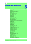
Download Removal and Installation 5
Transcript
Removal and Installation 5 6 Introduction 6-2 Service Calibration Guide to Removal and Installation 6-8 Window 6-13 Covers and Trims 5-17 Rear Tray 6-36 Rear Cover 6-37 Media Lever 6-38 Media Lever Position Sensor 6-41 Cutter Assembly 6-43 Left Rear Tray Support 6-46 Front Panel 6-48 Top Cover 6-51 Window Position Sensor 6-54 Ink Supply Tubes Support Rail 6-56 Service Station 6-60 Drop Detector 6-64 Aerosol Fan Assembly 6-65 Primer Assembly 6-67 PrintMech PCA 6-71 Pen to Paper Space (PPS) Solenoid 6-73 Spindle 6-75 Left Spindle Holder 6-76 Right Spindle Holder 6-77 Clean Out Assembly 6-78 Out Of Paper Sensor 6-79 Left Roll Guide 6-82 Right Roll Guide 6-83 Encoder Strip (with spring and attachment nut) 6-84 Clean Encoder Strip Procedure 6-86 Trailing Cable (with Carriage PCA Cover) 6-92 Carriage Assembly and Trailing Cable 6-100 Extra High PRS Wedge 6-109 Carriage Rear Bushing 6-113 Belt Assembly 6-115 Scan-Axis Motor 6-116 Carriage Rail Oiler 6-120 Color Sensor ESP (spectrophotometer) 6-122 Line Sensor 6-128 Carriage Cover (includes Carriage Latch) 6-133 Carriage PCA 6-138 Right Ink Supply Station 6-143 Left Ink Supply Station 6-147 Ink Supply Tubes 6-151 Formatter 6-159 Electronics Module (Main PCA and PSU) 6-161 Starwheel Assembly 6-164 Print Zone Overdrive 6-169 Left Spittoon 6-173 Encoder Disk and Encoder Sensor 6-176 Media Advance Drive 6-180 Media Advance Roller 6-185 Pinchwheel Assembly 6-191 Pinch Roller 6-199 Rubber Pinchwheel Kit 6-200 Left Starwheel Lifter 6-204 Right Starwheel Lifter 6-207 Starwheel Motor 6-211 Full Bleed Foam 6-213 Designjet Z Series — Service Manual 6-1 Removal and Installation Introduction This chapter is a step-by-step guide to the removal and installation of the key components of the printer. You may find it useful to check off the steps as they are performed. Use the illustrations for each procedure to identify the parts referred to in the text. The procedures appear in order of removal. The whole machine can be stripped down by starting at the beginning of this chapter and working through the subsequent procedures. Before using this chapter to remove and install a new component, always make sure that you have performed the relevant service test from Chapter 4. If the test passes you will not need to replace the component. Safety Precautions Review the instructions identified by WARNING and CAUTION symbols before you service the printer. Follow these warnings and cautions for your protection and to avoid damaging the printer. Serious shock hazard leading to death or injury may result if you do not take the following precautions: •Ensure that the ac power outlet (mains) has a protective earth (ground) terminal. •Switch the plotter off, and disconnect it from the power source prior to performing any maintenance. •Prevent water or other liquids from running onto electrical components or circuits, or through openings in the module. Electrostatic Discharge (ESD) Precautions To prevent damage to the Printer circuits from high-voltage electrostatic discharge (ESD): 1.Do not wear clothing that is subject to static build-up. 2. Do not handle integrated circuits (ICs) in carpeted areas. 3. Do not remove an IC or a printed circuit assembly (PCA) from its conductive foam pad or conductive packaging until you are ready to install it. 4. Ground (earth) your body while disassembling and working on the Printer. 5. After removing a cover from the Printer, attach an earthing (ground) lead between the PCA common and earth ground. Touch all tools to earth ground to remove static charges before using them on the Printer. 6. After removing any PCA from the Printer, place it on a conductive foam pad or into its conductive packaging to prevent ESD damage to any ICs on the PCA. 6-2 Designjet Z Series — Service Manual Removal and Installation - Introduction Required Tools All the special tools and equipment required to disassemble, service and repair the Printer are provided in the Toolkit P/N . Some tools can be ordered seperately from the toolkit. Refer to Page 524. The Toolkit contains the following tools: Description/Comments HP Part Number Spanner 13 mm Q6675-67011 Alcohol Q6675-60070 Allen Key #2 Q6675-60041 Cleaning Cloth 9300-2531 Cleaning Sponge/Bag Assembly C6071-60218 Flex Contacts Cleaning Support Q1271-60754 Lubricant Oil Q6675-60061 Isopropyl Alcohol Q6675-60091 Media Driver Adjustment Tool Q6675-67009 Handle for Media Driver Tool Support Q6675-67010 Oil Dispenser Q6675-60062 Pinchwheel Alignment Tool Q5669-20595 Pinchwheel Insertion Tool Q5669-20594 Protective Plastic Gloves Q6675-60035 T-15 Screwdriver 8710-2456 Tweezers Q6675-60037 You will also need the following standard hand tools: Standard Tool Requirements Description/Comments Long Torx Screwdriver Torx Bit (75 mm) Size 1/4 inch drive 8 10 15 20 Philips Screwdriver 1 Pliers N/A Snips N/A Pipe Spanner Flat Bladed Screwdriver Designjet Z Series — Service Manual 5.5 mm N/A 6-3 Removal and Installation System Diagrams Primer components Primer schematic 6-4 Designjet Z Series — Service Manual Removal and Installation - System Diagrams Electronic layout Designjet Z Series — Service Manual 6-5 Removal and Installation Main electronics and cabling 6-6 Designjet Z Series — Service Manual Removal and Installation - System Diagrams Ink supply station schematic Designjet Z Series — Service Manual 6-7 Removal and Installation Service Calibration Guide to Removal and Installation Using the Service Calibration Guide When you remove most printer components, you will need to perform a particular set of Service Calibrations and Diagnostic tests to ensure proper printer performance. The Service Calibration Matrix explains which service calibrations and diagnostic tests (top row) need to be performed whenever you remove and install particular printer components (left most column). A number in the body of the table indicates that the service calibration of the same column must be performed whenever you remove the corresponding component. The calibrations must be performed in the order they are numbered. Start by locating the component you have removed and installed in the left most column. Even if you do not replace the removed component with a new component, you still need to perform all the calibrations indicated by the matrix EXCEPT reset life counters, which only needs to be done when a new component is installed to replace a failing component. The Service Calibration Matrix 6-8 Service Station 1 2 3 Aerosol Fan Assembly 1 2 3 Drop Detector 1 2 Designjet Z Series — Service Manual Removal and Installation - Service Calibration Guide to Removal and Installation Service Station Spittoon 1 2 Primer Assembly 1 2 Left Ink Supply Station 1 Right Ink Supply Station 1 Carriage Cover 3 1 2 Carriage Latch 3 1 2 Carriage PCA 3 1 2 PrintMech PCA 1 Front Panel 1 Power Supply Unit (PSU) 1 Main PCA 1 Ink Supply Tubes 1 2 3 Media Advance Drive 1 3 2 Encoder Disk 1 3 2 Encoder Sensor 1 3 2 Media Advance Roller 1 3 Carriage Assembly 2 Designjet Z Series — Service Manual 5 4 1 4 2 3 6 6-9 Removal and Installation Belt Tensioner 2 1 4 3 Belt Assembly 2 1 4 3 5 Scan-Axis Motor 2 1 4 3 5 Trailing Cable 2 1 4 3 5 Carriage Rear Bushing 2 1 4 3 1 5 Line Sensor 3 2 Window Position Sensor 2 1 Out of Paper Sensor 1 Right Roll Guide 1 Left Roll Guide 1 Clean Out Assembly 1 Pen to Paper Space (PPS) Solenoid Encoder Strip 1 1 Starwheel Assembly 1 Starwheel Motor 1 2 Left Starwheel Lifter 1 2 Right Starwheel Lifter 6-10 Designjet Z Series — Service Manual Removal and Installation - Service Calibration Guide to Removal and Installation Print Zone Overdrive 1 Media Lever Position Sensor 1 Pinchwheel Assembly 1 2 Pinch Roller * If you replace more than half of the rollers, perform 3, Paper Advance Calibration 1 2 Preventive Maintenance Kit #1 2 1 3 4 3 Preventive Maintenance Kit #2 1 Preventive Maintenance Kit #3 1 Cutter Assembly 1 3 2 Color Sensor ESP (spectrophotometer) 3 Top Cover 1 Ink Supply Tubes Support 2 5 1 2 1 2 Rail Designjet Z Series — Service Manual 6-11 Removal and Installation Performing the Service Calibrations and Diagnostic Tests When you are ready to perform the service calibrations and diagnostic tests that correspond to the component you have installed or replaced, consult the following page numbers for procedures: PRS Test - Refer to Page 3-9. Scan Axis Test - Refer to Page 3-11. Cutter test - Refer to Page 3-16. Star Wheel Lifter test - Refer to Page 3-7. 2. Paper Drive - Refer to Page 3-18. 3. Electronics Module - Refer to Page 3-22. 4. Carriage Assembly - Refer to Page 3-27. 5. Sensors - Refer to Page 3-33. 6. Color Sensor ESP (spectrophotometer) - Refer to Page 3-36. 7. Ink Delivery System (IDS) - Refer to Page 3-38. 8. Service Station - Refer to Page 3-45. Paper Advance Calibration - Refer to Page 4-6. Drop Detector Calibration - Refer to Page 4-12. Line Sensor Calibration - Refer to Page 4-15. 4. Reset Life Counters - Refer to Page 3-66. (after replacement only) 6-12 Designjet Z Series — Service Manual Removal and Installation - Window Window Removal Switch off the printer and remove the power cable. The Window can also be removed with the Top Cover to avoid scratching the Window. To remove the Window with the Top Cover, Refer to Page 6-51. 1. Open the Window. 2. Remove the two T-15 screws that secure the left Window hinge locking plate to the Top Cover. 3. Remove the left Window hinge locking plate from the Top Cover. Designjet Z Series — Service Manual 6-13 Removal and Installation 4. Remove the Damper Rotary from the Top Cover. 5. Remove the T-15 screws that secure each of the remaining three Window hinge locking plates to the Top Cover. 6. Remove the remaining three Window hinge locking plates from the Top Cover. 6-14 Designjet Z Series — Service Manual Removal and Installation - Window 7. Remove the remaining three Damper Rotary pieces from the Top Cover. 8. Grip the Window at the left and right edges and move it horizontally towards the right as far as it will go. 9. Pull the Window towards the front to disengage the hinges. Designjet Z Series — Service Manual 6-15 Removal and Installation 10. Lift the Window vertically out of the printer. 6-16 Designjet Z Series — Service Manual Removal and Installation - Front Cover Front Cover Removal Switch off the printer and remove the power cable. 1. Squeeze each of the four attachment clips under the Front Cover, to release the cover from the printer. 2. Carefully pull the bottom of the Front Cover forwards until you can release it from its attachments. 3. Unhook the Front Cover from the four attachments and remove it from the printer. 1 2 Designjet Z Series — Service Manual 6-17 Removal and Installation Media Output Assembly Removal Switch off the printer and remove the power cable. 1. Remove the Front Cover (refer to page 617). 2. Remove four T-15 screws that secure the Media Output Assembly to the printer. On some printers, the Left and Right Front Trim is integrated with the Output Support. On some 24 inch printers, the center Output Support is replaced by a small cylinder (that is not attached to the Media Output Assembly). Otherwise, the procedure remains the same, but the printer may appear differently than shown. 3. Release the four attachment clips. 4. Unclip the Media Output Assembly from the clips and remove it from the printer. 2 1 6-18 Designjet Z Series — Service Manual Removal and Installation - Right Front Trim Right Front Trim Removal Switch off the printer and remove the power cable. 1. Remove the Front Cover (refer to page 617). 2. Remove the Media Output Assembly (refer to page 6-18). 3. Remove two T-15 screws that secure the Right Front Trim to the printer. On some printers, the Right Front Trim is integrated with the Output Support. In this case, you need to remove three screws that secure the Right Front Trim to the printer (shown in the small graphic on the left). Once you have removed the three screws, you are free to remove the Right Front Trim from the printer. 4. Open the Right Ink Cartridge Door. 5. Unclip the Right Front Trim. Designjet Z Series — Service Manual 6-19 Removal and Installation 6. Remove Right Front Trim from the printer. 6-20 Designjet Z Series — Service Manual Removal and Installation - Left Front Trim Left Front Trim Removal Switch off the printer and remove the power cable. 1. Remove the Front Cover (refer to page 617). 2. Remove the Media Output Assembly (refer to page 6-18). 3. Remove two T-15 screws that secure the Left Front Trim to the printer. On some printers, the Left Front Trim is integrated with the Output Support. In this case, you need to remove three screws that secure the Left Front Trim to the printer (shown in the small graphic on the left). Once you have removed the three screws, you are free to remove the Left Front Trim from the printer. 4. Open the Left Ink Cartridge Door. 5. Unclip the Left Front Trim. Designjet Z Series — Service Manual 6-21 Removal and Installation 6. Remove Left Front Trim from the printer. 6-22 Designjet Z Series — Service Manual Removal and Installation - Right Ink Cartridge Door Right Ink Cartridge Door Removal Switch off the printer and remove the power cable. 1. Open the Right Ink Cartridge Door. 2. Unclip the right side of the Right Ink Cartridge Door. 3. Unclip the left side of the Right Ink Cartridge Door. Designjet Z Series — Service Manual 6-23 Removal and Installation 4. Remove the Right Ink Cartridge Door. 6-24 Designjet Z Series — Service Manual Removal and Installation - Left Ink Cartridge Door Left Ink Cartridge Door Removal Switch off the printer and remove the power cable. 1. Open the Left Ink Cartridge Door. 2. Unclip the left side of the Left Ink Cartridge Door. 3. Unclip the right side of the Left Ink Cartridge Door. Designjet Z Series — Service Manual 6-25 Removal and Installation 4. Remove the Left Ink Cartridge Door. 6-26 Designjet Z Series — Service Manual Removal and Installation - Right Cover Right Cover Removal Switch off the printer and remove the power cable. 1. Remove the Front Cover (refer to page 617). 2. Open the Right Ink Cartridge Door. 3. Remove the Ink Cartridges from the printer. 4. Remove one T-15 screw that secures the Right Cover to the printer (at the rear of the Printer). Designjet Z Series — Service Manual 6-27 Removal and Installation 5. Remove one T-15 screw that secures the Right Cover to the printer (at the rear of the Printer). 6. Remove one T-15 screw that secures the Right Cover to the printer (at the rear of the printer). 7. 6-28 Remove one T-15 screw that secures the Right Cover to the printer (accessible under the Front Cover). Designjet Z Series — Service Manual Removal and Installation - Right Cover 8. Remove one T-15 screw that secures the Right Cover to the printer (accessible from within the cartridge bay). 9. Unclip the Right Trim. 10. Remove the Right Cover from the printer. Designjet Z Series — Service Manual 6-29 Removal and Installation Left Cover Removal Switch off the printer and remove the power cable. 1. Remove the Front Cover (refer to page 617) 2. Open the Left Ink Cartridge Door. 3. Press the clip to release the Left Cover Finishing Panel. 4. Remove the Left Cover Finishing Panel. 6-30 Designjet Z Series — Service Manual Removal and Installation - Left Cover 5. Unclip the spring from the attachment points on the Media Lever and Left Cover. 1 2 6. Remove three T-15 screws that secure the Media Lever. 7. Designjet Z Series — Service Manual Remove the Ink Cartridges from the Printer. The illustration shows the Z2100 which has only two Ink Cartridges, for the Z3100 there are six Ink Cartridges. 6-31 Removal and Installation 8. For the Z2100, carefully push the edge of the Ink Trim Assembly to the left. For the Z3100, continue from step 11 of this procedure. 9. Lift the right edge of the Ink Trim Assembly. 10. Remove the Ink Trim Assembly from the Printer. 6-32 Designjet Z Series — Service Manual Removal and Installation - Left Cover 11. Use a flat bladed screwdriver to unclip the two attachment clips of the Formatter Housing. 12. Lift the Formatter Housing out of the printer. 13. Remove one T-15 screw that secures the Left Cover (top rear, accessible under the Formatter Housing). Designjet Z Series — Service Manual 6-33 Removal and Installation 14. Remove one T-15 screw that secures the Left Cover (bottom rear). 15. Remove one T-15 screw that secures the Left Cover (bottom rear). 16. Remove one T-15 screw that secures the Left Cover (bottom front, accessible under Front Cover). 6-34 Designjet Z Series — Service Manual Removal and Installation - Left Cover 17. Remove one T-15 screw that secures the Left Cover (top front, accessible Ink Cartridge Door). 18. Unclip the Left Trim. 19. Remove the Left Cover from the Printer. Designjet Z Series — Service Manual 6-35 Removal and Installation Rear Tray Removal Switch off the printer and remove the power cable. 1. Open the Rear Tray to approximately 10 degrees less than the fully open position. Some printers have Rear Trays with tray extensions and some printers do not have extension trays. Rear Tray with tray extensions shown. 2. Lift the Rear Tray vertically enough (approximately 20 mm) to allow the rear attachment lugs to be out of the locked position. Rear Tray with tray extensions shown. 3. Carefully slide the Rear Tray out of the printer. Rear Tray with tray extensions shown. 6-36 Designjet Z Series — Service Manual Removal and Installation - Rear Cover Rear Cover Removal Switch off the printer and remove the power cable. 1. Remove the Rear Tray (refer to page 6-36). 2. Remove the Right Cover (refer to page 627). 3. Remove the Left Cover (refer to page 6-30). 4. Remove ten T-15 screws that secure the Rear Cover to the printer. 5. Remove the Rear Cover from the printer. Designjet Z Series — Service Manual 6-37 Removal and Installation Media Lever Removal Switch off the printer and remove the power cable. 1. Open the Ink Cartridge Door. 2. Press the clip to release the Left Cover Finishing Panel. 3. Remove the Left Cover Finishing Panel. 6-38 Designjet Z Series — Service Manual Removal and Installation - Media Lever 4. Unclip the spring from the attachment points on the Media Lever and Left Cover. 1 2 5. Remove three T-15 screws that secure the Media Lever. 6. Lift the Media Lever of the mounting. Designjet Z Series — Service Manual 6-39 Removal and Installation 7. 6-40 Remove the Media Lever from the printer. Designjet Z Series — Service Manual Removal and Installation - Media Lever Position Sensor Media Lever Position Sensor Removal Switch off the printer and remove the power cable. 1. Raise the Media Lever. 2. Remove the Left Cover (refer to page 6-30). 3. Disconnect the Media Lever Position Sensor. 4. Remove one T-15 screw that secures the Media Lever Position Sensor to the Scan Side Panel. 5. Rotate the Media Lever Position Sensor vertically to disengage the attachment lug from the Scan Side Panel. Designjet Z Series — Service Manual 6-41 Removal and Installation 6. Remove the Media Lever Position Sensor. When you finish installing or replacing this component, you must perform the necessary Service Calibrations. To find which calibrations you must perform, Refer to page 6-8, Service Calibration Guide to Removal and Installation. 6-42 Designjet Z Series — Service Manual Removal and Installation - Cutter Assembly Cutter Assembly Removal Switch off the printer and remove the power cable. 1. Remove the Left Cover Finishing Panel (refer to step 3 of the Left Cover removal procedure on page 5-30). 2. Fully loosen the cutter rail end cap attachment screw. 3. Remove the cutter rail end cap. 4. Slide the Cutter Assembly out of the printer. When you install the new Cutter Assembly, follow the installation instructions provided with the new Cutter Assembly. Designjet Z Series — Service Manual 6-43 Removal and Installation Right Rear Tray Support Removal Switch off the printer and remove the power cable. 1. Remove the Rear Tray (refer to page 6-36). 2. Remove the Right Cover (refer to page 627). 3. Remove the Left Cover (refer to page 6-30). 4. Remove the Rear Cover (refer to page 637). 5. Remove two T-15 screws that secure the Right Rear Tray Support to the printer. 6. Rotate the Right Rear Tray Support counterclockwise approximately 30 degrees. 6-44 Designjet Z Series — Service Manual Removal and Installation - Right Rear Tray Support 7. Designjet Z Series — Service Manual Remove the Right Rear Tray Support from the printer. 6-45 Removal and Installation Left Rear Tray Support Removal Switch off the printer and remove the power cable. 1. Remove the Rear Tray (refer to page 6-36). 2. Remove the Right Cover (refer to page 627). 3. Remove the Left Cover (refer to page 6-30). 4. Remove the Rear Cover (refer to page 637). 5. Remove two T-15 screws that secure the Left Rear Tray Support to the printer. 6. Rotate the Left Rear Tray Support clockwise approximately 30 degrees. 6-46 Designjet Z Series — Service Manual Removal and Installation - Left Rear Tray Support 7. Designjet Z Series — Service Manual Remove the Left Rear Tray Support from the printer. 6-47 Removal and Installation Front Panel Removal Switch off the printer and remove the power cable. 1. Open the Window. 2. With strong pressure, squeeze the top edge of the front panel enough to release the attachment clips, and begin rotating the Front Panel vertically in the next step. 3. Rotate the front panel vertically. 6-48 Designjet Z Series — Service Manual Removal and Installation - Front Panel 4. Disconnect the interface cable from the Front Panel. 5. Push in the clip that prevents the Ferrite Core from being removed. Some printers do not have a Ferrite Core. If the printer does not have a Ferrite Core, carefully remove the interface cable from the Front Panel. If the printer does have a Ferrite Core, continue with the service manual procedure. 6. Slide the Ferrite Core out of the brackets. Designjet Z Series — Service Manual 6-49 Removal and Installation 7. Remove the Front Panel. When you reinstall the Front Panel, you must make sure that the Ferrite Core is correctly positioned. The Ferrite Core is necessary to avoid electrostatic interference being generated. When you finish installing or replacing this component, you must perform the necessary Service Calibrations. To find which calibrations you must perform, Refer to page 6-8, Service Calibration Guide to Removal and Installation. 6-50 Designjet Z Series — Service Manual Removal and Installation - Top Cover Top Cover Removal Switch off the printer and remove the power cable. 1. Remove the Window (refer to page 6-13). 2. Remove the Right Cover (refer to page 627). 3. Remove the Left Cover (refer to page 6-30). 4. Remove the Rear Tray (refer to page 6-36). 5. Remove the Rear Cover (refer to page 637). 6. Remove the Front Panel (refer to page 648). 7. Remove the four T-15 top screws that secure the Top Cover to the printer. 8. Remove the front T-15 screw that secures the front left side of the Top Cover to the printer. Designjet Z Series — Service Manual 6-51 Removal and Installation 9. Carefully pull the attachment clip forward until you can lift the bottom left corner of the Top Cover approximately 10 mm. 2 1 10. Remove the front T-15 screw that secures the front left side of the Top Cover to the printer. 2 11. Carefully pull the attachment clip forward until you can lift the bottom left corner of the Top Cover approximately 10 mm. 1 6-52 Designjet Z Series — Service Manual Removal and Installation - Top Cover 12. Lift the Top Cover of the printer sufficiently to gain access to the Front Panel ribbon cable. 13. Unroute the Front Panel ribbon cable from the two cable clamps on the bottom surface of the Top Cover. 14. Lift the Top Cover off the printer. When you finish installing or replacing this component, you must perform the necessary Service Calibrations. To find which calibrations you must perform, Refer to page 6-8, Service Calibration Guide to Removal and Installation. Designjet Z Series — Service Manual 6-53 Removal and Installation Window Position Sensor Removal Switch off the printer and remove the power cable. 1. Remove the Right Cover (refer to page 627). 2. Remove the Left Cover (refer to page 6-30). 3. Remove the Front Panel (refer to page 648). 4. Remove the Top Cover (refer to page 651). 5. Disconnect the Window Position Sensor. 6. Remove one T-15 screw that secures the Window Position Sensor to the printer. 6-54 Designjet Z Series — Service Manual Removal and Installation - Window Position Sensor 7. Remove the Window Position Sensor to the printer. When you finish installing or replacing this component, you must perform the necessary Service Calibrations. To find which calibrations you must perform, Refer to page 6-8, Service Calibration Guide to Removal and Installation. Designjet Z Series — Service Manual 6-55 Removal and Installation Ink Supply Tubes Support Rail Removal Switch off the printer and remove the power cable. 1. Remove the Right Cover (refer to page 627). 2. Remove the Left Cover (refer to page 6-30). 3. Remove the Front Panel (refer to page 648). 4. Remove the Top Cover (refer to page 651). 5. Remove the Window Position Sensor (refer to page 6-54). 6. Remove the Ink Supply Tubes from the Ink Supply Tubes Support Rail. 7. 6-56 Remove the T-15 screws that secure the rear attachment brackets to the Ink Supply Tubes Support Rail. Designjet Z Series — Service Manual Removal and Installation - Ink Supply Tubes Support Rail 8. Remove the T-15 screw that attaches the right bonding cable. 9. Remove the T-15 screw that attaches the left bonding cable. 10. Remove the T-15 screw that attaches the left bonding cable. If you are working with a newer printer, the screw location may be different. Designjet Z Series — Service Manual 6-57 Removal and Installation 11. Remove two T-15 screws that secure the Ink Supply Tubes Support Rail to the right Top Cover Support. 12. Remove two T-15 screws that secure the Ink Supply Tubes Support Rail to the left Top Cover Support. 13. Slide the rail to the enough to disengage it from the attachment lug. 6-58 Designjet Z Series — Service Manual Removal and Installation - Ink Supply Tubes Support Rail 14. Carefully slide the Ink Supply Tubes Support Rail to the left until the right end is clear of the right Top Cover Support. 15. Remove the Ink Supply Tubes Support Rail from the printer. When you reinstall the Ink Supply Tubes Support Rail make sure that the attachment lug is correctly engaged with the right Top Cover Support. When you reinstall the Ink Supply Tubes Support Rail make sure all the attachment brackets and bonding leads are correctly connected. These are important to avoid electrostatic interference being generated. When you finish installing or replacing this component, you must perform the necessary Service Calibrations. To find which calibrations you must perform, Refer to page 6-8, Service Calibration Guide to Removal and Installation. Designjet Z Series — Service Manual 6-59 Removal and Installation Service Station Removal Switch off the printer and remove the power cable. 1. Remove the Right Cover (refer to page 627). 2. Disconnect the Ink Supply Station ribbon connector and two lower connectors from the PrintMech PCA. The Ink Supply Station ribbon connector has to be disconnected so the other cables can an be unrouted 3. Unroute the two cables disconnected in step 2 from the two cable clamps below the PrintMech PCA. 4. Remove the grounding cable attachment screw from the PrintMech PCA. 6-60 Designjet Z Series — Service Manual Removal and Installation - Service Station 5. Disconnect connector from the Drop Detector Motor and Drop Detector Sensor. 6. Unroute the cables disconnected in steps 4 and 5 from the two cable clamps. 7. Disconnect the Aerosol Fan Assembly inline connector. Some printers function without an aerosol fan. If the printer does not have an aerosol fan, make the inline connection during installation even though there is no fan. Designjet Z Series — Service Manual 6-61 Removal and Installation 8. Loosen the T-10 uncapping screw sufficiently so you can manually move the Carriage Assembly in step 9. 9. Push the Carriage Assembly into the print path to gain access to two T-15 screws that secure the Service Station to the Carriage Rail. 10. Use a allen key provided in the tool kit to remove two allen screws that secure the Service Station to the Carriage Rod. Support the Service Station so it does not fall when you remove the attachment screws. 6-62 Designjet Z Series — Service Manual Removal and Installation - Service Station 11. Unclip the clip to release the Service Station from the printer. 12. Lower the Service Station from the printer. 13. Lower the right of the Service Station enough to allow you to slide it carefully out of the printer. When you finish installing or replacing this component, you must perform the necessary Service Calibrations. To find which calibrations you must perform, Refer to page 6-8, Service Calibration Guide to Removal and Installation. Designjet Z Series — Service Manual 6-63 Removal and Installation Drop Detector Removal Switch off the printer and remove the power cable. 1. Remove the Right Cover (refer to page 627). 2. Remove the Service Station (refer to page 6-60). 3. Unroute the Drop Detector ribbon cable from the Service Station cable clamps. 4. Remove the T-15 screw that secures the Drop Detector to the Service Station. 5. Lift the Drop Detector off the Service Station. When you finish installing or replacing this component, you must perform the necessary Service Calibrations. To find which calibrations you must perform, Refer to page 6-8, Service Calibration Guide to Removal and Installation. 6-64 Designjet Z Series — Service Manual Removal and Installation - Aerosol Fan Assembly Aerosol Fan Assembly Removal Switch off the printer and remove the power cable. 1. Remove the Right Cover (refer to page 627). 2. Disconnect the Aerosol Fan Assembly inline connector. 3. Remove the four T-15 screws that secure the Aerosol Fan Assembly to the Service Station. The four access holes in the Aerosol Fan Assembly housing are the same size as the attachment screw diameter so you will need a normal Torx Screwdriver, not a multi-tool, to remove the screws. Designjet Z Series — Service Manual 6-65 Removal and Installation 4. Remove the Aerosol Fan Assembly from the Service Station. When you reinstall the Aerosol Fan Assembly make sure you position it so that the power cable is on the outside exiting to the right. When you finish installing or replacing this component, you must perform the necessary Service Calibrations. To find which calibrations you must perform, Refer to page 6-8, Service Calibration Guide to Removal and Installation. 6-66 Designjet Z Series — Service Manual Removal and Installation - Primer Assembly Primer Assembly Removal Switch off the printer and remove the power cable. 1. Remove the Right Cover (refer to page 627). 2. Remove the Service Station (refer to page 6-60). 3. Pull out the spitting tube from the Service Station Spittoon and unroute it from the attachment clip. 4. Unroute the cable assembly from attachment clip on the Service Station Spittoon. 5. Unclip the front left clip that secures the Service Station to the Service Station Spittoon. Designjet Z Series — Service Manual 6-67 Removal and Installation 6. Unclip the front left clip that secures the Service Station to the Service Station Spittoon. 7. Carefully raise the Service Station vertically from the clip side (by approximately 30 degrees) until you can disengage it form the three attachments on the opposite side to remove it from the Left Spittoon. 8. Disconnect the three Primer Assembly tubes. It is recommended that you use protective gloves when handling the Primer Assembly Use a suitable method to identify each Primer Assembly tube for correct re-connection during assembly components. 6-68 Designjet Z Series — Service Manual Removal and Installation - Primer Assembly 9. Unroute the three Primer Assembly tubes. 10. Remove the T-15 screw that secure the Primer Assembly to the Service Station. 11. Tilt the Primer Assembly to disengage the lower edge. Designjet Z Series — Service Manual 6-69 Removal and Installation 12. Lower the Primer Assembly to disengage the top attachment lugs. 13. Remove the Primer Assembly from the Service Station. When you install the Primer Assembly make sure you connect the three primer tubes in accordance with their identification markings. When you finish installing or replacing this component, you must perform the necessary Service Calibrations. To find which calibrations you must perform, Refer to page 6-8, Service Calibration Guide to Removal and Installation. 6-70 Designjet Z Series — Service Manual Removal and Installation - PrintMech PCA PrintMech PCA Removal Do NOT remove and install both the PrintMech PCA and the Formatter at the same time. If you have previously removed and installed the Formatter, make sure that you complete the procedure and the instructions provided on the flyer that accompanies the Formatter. Refer to Page 6-159 before installing the PrintMech PCA. Switch off the printer and remove the power cable. 1. Remove the Right Cover (refer to page 627). 2. Disconnect all the electrical connectors from the PrintMech PCA. 3. Remove the grounding cable attachment screw from the PrintMech PCA. Designjet Z Series — Service Manual 6-71 Removal and Installation 4. Remove the three T-15 screws that secure the PrintMech PCA to the Service Station. 5. Remove the PrintMech PCA from the printer. When you finish installing or replacing this component, you must perform the necessary Service Calibrations. To find which calibrations you must perform, Refer to page 6-8, Service Calibration Guide to Removal and Installation. 6-72 Designjet Z Series — Service Manual Removal and Installation - Pen to Paper Space (PPS) Solenoid Pen to Paper Space (PPS) Solenoid Removal Switch off the printer and remove the power cable. 1. Remove the Right Cover (refer to page 627). 2. Unroute the Pen to Paper Space (PPS) Solenoid cable from the cable clamp. 3. Disconnect the Pen to Paper Space (PPS) Solenoid connector from the PrintMech PCA. 4. Remove two T-15 screws that secure the Pen to Paper Space (PPS) Solenoid to the printer. Designjet Z Series — Service Manual 6-73 Removal and Installation 5. Remove the Pen to Paper Space (PPS) Solenoid from the printer. When you finish installing or replacing this component, you must perform the necessary Service Calibrations. To find which calibrations you must perform, Refer to page 6-8, Service Calibration Guide to Removal and Installation. 6-74 Designjet Z Series — Service Manual Removal and Installation - Spindle Spindle Removal Switch off the printer and remove the power cable. 1. Pull the left end of the Spindle (viewed from the front of the printer) out of the Left Spindle Holder. It is normal to encounter Spindles of different diameters and weights. Rear Tray with tray extensions shown. 2. Lift the Spindle out of the printer towards the left (viewed from the front of the printer). Rear Tray with tray extensions shown. Designjet Z Series — Service Manual 6-75 Removal and Installation Left Spindle Holder Removal Switch off the printer and remove the power cable. 1. Remove the Spindle (refer to page 6-75). 2. Remove two T-15 screws that secure the Left Spindle Holder to the printer. 3. Rotate the Left Spindle Holder towards the left. 4. Remove the Left Spindle Holder from the printer. 6-76 Designjet Z Series — Service Manual Removal and Installation - Right Spindle Holder Right Spindle Holder Removal Switch off the printer and remove the power cable. 1. Remove the Spindle (refer to page 6-75). 2. Remove two T-15 screws that secure the Right Spindle Holder to the printer. 3. Rotate the Right Spindle Holder towards the right. 4. Remove the Right Spindle Holder from the printer. Designjet Z Series — Service Manual 6-77 Removal and Installation Clean Out Assembly Removal Switch off the printer and remove the power cable. 1. Remove the Spindle (refer to page 6-75). 2. Disconnect the Out Of Paper Sensor in-line connector and unroute the its cable. 3. Remove the four T-15 screws that secure Clean Out Assembly to the printer. Rear Tray with tray extensions shown. 4. Beginning with the left side, slide the Clean Out Assembly out of the printer. Double check that you haven´t broken the Out Of Paper Sensor on the left side of the Clean Out Assembly. Rear Tray with tray extensions shown. 6-78 When you finish installing or replacing this component, you must perform the necessary Service Calibrations. To find which calibrations you must perform, Refer to page 6-8, Service Calibration Guide to Removal and Installation. Designjet Z Series — Service Manual Removal and Installation - Out Of Paper Sensor Out Of Paper Sensor Removal Switch off the printer and remove the power cable. 1. Remove the Spindle (refer to page 6-75). 2. Remove the Clean Out Assembly (refer to page 6-78). 3. Unroute the Out Of Paper Sensor electrical cables from the Clean Out Assembly. 4. Unroute (unwind) the Out Of Paper Sensor electrical cables from the Out Of Paper Sensor cover. 5. Press the clip to remove the Out Of Paper Sensor cover from the Clean Out Assembly. Designjet Z Series — Service Manual 6-79 Removal and Installation 6. Rotate the Out Of Paper Sensor cover approximately 45 degrees. 7. Remove the Out Of Paper Sensor cover from the Clean Out Assembly 8. Squeeze the Out Of Paper Sensor attachment clips to remove it from the Clean Out Assembly. 6-80 Designjet Z Series — Service Manual Removal and Installation - Out Of Paper Sensor 9. Lift the Out Of Paper Sensor out of the Clean Out Assembly. When you finish installing or replacing this component, you must perform the necessary Service Calibrations. To find which calibrations you must perform, Refer to page 6-8, Service Calibration Guide to Removal and Installation. Designjet Z Series — Service Manual 6-81 Removal and Installation Left Roll Guide Removal Switch off the printer and remove the power cable. 1. Remove the Spindle (refer to page 6-75). 2. Remove the Clean Out Assembly (refer to page 6-78). 3. Remove five T-15 screws that secure Left Roll Guide to the printer. 4. Lower the left end and remove the Left Roll Guide from the printer. When you finish installing or replacing this component, you must perform the necessary Service Calibrations. To find which calibrations you must perform, Refer to page 6-8, Service Calibration Guide to Removal and Installation. 6-82 Designjet Z Series — Service Manual Removal and Installation - Right Roll Guide Right Roll Guide Removal Switch off the printer and remove the power cable. 1. Remove the Spindle (refer to page 6-75). 2. Remove the Clean Out Assembly (refer to page 6-78). 3. Remove the Left Roll Guide (refer to page 6-82). 4. Remove seven T-15 screws that secure Right Roll Guide to the printer. 5. Lower the right end and remove the Right Roll Guide from the printer. When you finish installing or replacing this component, you must perform the necessary Service Calibrations. To find which calibrations you must perform, Refer to page 6-8, Service Calibration Guide to Removal and Installation. Designjet Z Series — Service Manual 6-83 Removal and Installation Encoder Strip (with spring and attachment nut) Removal Switch off the printer and remove the power cable. 1. Remove the Right Cover (refer to page 627). 2. Remove the Left Cover (refer to page 6-30). 3. Remove the T-15 screw that secures Encoder Strip to the printer. 4. Grip the Encoder Strip and move it towards the left to take off the tension until you have completed the next step. 5. Unclip the Encoder Strip from it’s attachment lugs. 6-84 Designjet Z Series — Service Manual Removal and Installation - Encoder Strip (with spring and attachment nut) 6. Loosen the T-10 uncapping screw sufficiently so you can manually move the Carriage Assembly in step 7. 7. Push the Carriage Assembly into the print path. 8. Unclip the Encoder Strip tensioner from the right hand end. There are two sizes of nuts on the Encoder Strip tensioner. If you are working with a newer printer, the nut will be smaller. 2 1 Designjet Z Series — Service Manual 6-85 Removal and Installation 9. Carefully pull the Encoder Strip out of the printer from the right hand end. When you finish installing or replacing this component, you must perform the necessary Service Calibrations. To find which calibrations you must perform, Refer to page 6-8, Service Calibration Guide to Removal and Installation. Clean Encoder Strip Procedure 1. Make sure that the printer is OFF and that the carriage assembly is located at the service station on the far right side of the printer. 2. Use tap water and a small cloth that will not leave fibers in the printer to clean the encoder strip. Dampen the cloth and remove any excess water so that the cloth is damp but not wet. 6-86 Designjet Z Series — Service Manual Removal and Installation - Encoder Strip (with spring and attachment nut) 3. Open the window. 4. Hold the cloth in an inverted "U" shape around the encoder strip and carefully wipe until no ink residue appears on the cloth. Be very careful not to scratch the encoder strip with your fingernail or any other object. 5. Do not hold the cloth as shown. Designjet Z Series — Service Manual 6-87 Removal and Installation 6. Hold the cloth as shown, in the appropriate "U" shape. 7. Do not move the carriage assembly away from the service station. 8. Close the window. 6-88 Designjet Z Series — Service Manual Removal and Installation - Encoder Strip (with spring and attachment nut) 9. On the front panel, select the ink icon, and then select Replace Printheads. The carriage assembly moves to the left and stops in the correct position to remove the printheads. 10. Turn off the printer the power switch on the back of the printer. 11. Open the window and move the carriage assembly further to the left, allowing you to access the service station. Designjet Z Series — Service Manual 6-89 Removal and Installation 12. Clean the part of the encoder strip next to the service station by repeating steps 2 to 6. 13. Close the window. When you are done, make sure to turn the printer back on. 6-90 Designjet Z Series — Service Manual Removal and Installation - Encoder Strip Encoder Strip Removal Switch off the printer and remove the power cable. 1. Remove the Right Cover (refer to page 627). 2. Remove the Left Cover (refer to page 6-30). 3. Remove the Encoder Strip (with spring and attachment nut) (refer to page 6-84). 4. Use the spanner provided in the tool kit to remove the 13 mm locking nut that secures the Encoder Strip to the Encoder Strip Spring. There are two sizes of nuts. If you are working with a newer printer, the nuts will be smaller. 5. Remove the Encoder Strip Spring. When you finish installing or replacing this component, you must perform the necessary Service Calibrations. To find which calibrations you must perform, Refer to page 6-8, Service Calibration Guide to Removal and Installation. Designjet Z Series — Service Manual 6-91 Removal and Installation Trailing Cable (with Carriage PCA Cover) Removal Switch off the printer and remove the power cable. 1. Remove the Left Cover (refer to page 6-30). 2. Remove the Right Cover (refer to page 627). 3. Remove the Front Panel (refer to page 648). 4. Remove the Top Cover (refer to page 651). 5. Remove the Window Position Sensor (refer to page 6-54). 6. Remove the Ink Supply Tubes Support Rail (refer to page 6-56). 7. Loosen the T-10 uncapping screw sufficiently so you can manually move the Carriage Assembly in step 8. 8. Push the Carriage Assembly into the print path. 6-92 Designjet Z Series — Service Manual Removal and Installation - Trailing Cable (with Carriage PCA Cover) 9. Unclip the small cover of the Carriage PCA. 10. Remove the small cover of the Carriage PCA. 11. Disconnect the two ribbon cables of the Trailing Cables from the Carriage PCA. Designjet Z Series — Service Manual 6-93 Removal and Installation 12. Straighten the two ribbon cables of the Trailing Cables and remove the Ferrite Core. 13. Slide the Trailing Cables out of the attachment clips of the Carriage Assembly. 14. Use a short torx screwdriver to remove the two T-10 screws that secure the center attachment of the Trailing Cables. 6-94 Designjet Z Series — Service Manual Removal and Installation - Trailing Cable (with Carriage PCA Cover) 15. Unclip the center attachment of the Trailing Cables. 2 1 16. Remove the Trailing Cables from the double sided adhesive pad that attaches it to the printer. Some printers have clips instead of adhesive pads that attach the Trailing Cables to the printer. In this case, unclip the Trailing Cables from the printer. 17. Disconnect the two ribbon cables of the Trailing Cables from the Electronics Module. Designjet Z Series — Service Manual 6-95 Removal and Installation 18. Unroute the Trailing Cables. 19. Unclip and remove the cable clamp of the Trailing Cables. 20. Unclip and remove the cable clamp of the Trailing Cables. 6-96 Designjet Z Series — Service Manual Removal and Installation - Trailing Cable (with Carriage PCA Cover) 21. Unroute the Trailing Cables. 22. Remove the Trailing Cables from the printer. Installation Make sure to install the new Carriage PCA Cover when you reinstall the Trailing Cable. Some printers have clips instead of adhesive pads that attach the Trailing Cables to the printer. Use the adhesive pads or clips that are included in the Trailing Cable service kit, replacing the clips or adhesive pads as necessary. When you finish installing or replacing this component, you must perform the necessary Service Calibrations. To find which calibrations you must perform, Refer to page 6-8, Service Calibration Guide to Removal and Installation. Make sure you carry out the following actions during the installation of the Trailing Cable 1. Use an alcohol (from the Lubrification Kit or Tool Kit) dampened cloth to remove all traces of residual adhesive (remaining from the double sided pads removed in step 16) from the printer before applying new pads in the same positions as the original pads. Designjet Z Series — Service Manual 6-97 Removal and Installation 2. Make sure both ribbon cables of the Trailing Cable are routed below the lower attachment clips of the Carriage Assembly. 3. Make sure that the Ferrite Core is correctly positioned so that the small cover of the Carriage PCA closes correctly to avoid possible friction damage to the Trailing Cable during operation of the printer. 4. When you replace the Carriage PCA Cover, use the new part included in the Carriage PCA service kit. 6-98 Designjet Z Series — Service Manual Removal and Installation - Trailing Cable (with Carriage PCA Cover) 5. Make sure that the Carriage PCA Cover is closed correctly to avoid damage to the Trailing Cable. Designjet Z Series — Service Manual 6-99 Removal and Installation Carriage Assembly and Trailing Cable Removal Switch off the printer and remove the power cable. 1. Remove the Front Cover (refer to page 617). 2. Remove the Right Cover (refer to page 627). 3. Remove the Left Cover (refer to page 6-30). 4. Remove the Cutter Assembly (refer to page 6-43). 5. Remove the Front Panel (refer to page 648). 6. Remove the Top Cover (refer to page 651). 7. Remove the Window Position Sensor (refer to page 6-54). 8. Remove the Ink Supply Tubes Support Rail (refer to page 6-56). 9. Loosen the T-10 uncapping screw to manually uncap the Service Station before removing the Encoder Strip (with spring and attachment nut) (refer to page 6-84). 10. Remove the Encoder Strip (with spring and attachment nut) (refer to page 6-84). 11. If necessary manually move the Carriage Assembly fully right into the docking station. 12. Use a short torx screwdriver to remove the two T-10 screws that secure the center attachment of the Trailing Cables. 6-100 Designjet Z Series — Service Manual Removal and Installation - Carriage Assembly and Trailing Cable 13. Unclip the center attachment of the Trailing Cables. 2 1 14. Remove the Trailing Cables from the two double sided adhesive pads that attach it to the printer. Some printers have clips instead of adhesive pads that attach the Trailing Cables to the printer. In this case, unclip the Trailing Cables from the printer. 15. Disconnect the two ribbon cables of the Trailing Cables from the Electronics Module. Designjet Z Series — Service Manual 6-101 Removal and Installation 16. Unroute the Trailing Cables. 17. Unclip and remove the cable clamp of the Trailing Cables. 18. Unclip and remove the cable clamp of the Trailing Cables. 6-102 Designjet Z Series — Service Manual Removal and Installation - Carriage Assembly and Trailing Cable 19. Unroute the Trailing Cables. 20. Open the Carriage Cover. The illustration shows the Z2100 which has four Printheads. For the Z3100, there are six Printheads. 21. Remove all the Printheads. Designjet Z Series — Service Manual 6-103 Removal and Installation 22. Remove the four T-15 screws that secure the Ink Supply Tubes to the Carriage Assembly. 23. Carefully lift out the Ink Supply Tubes and close the carriage cover at the same time. 24. Close and lock the Carriage Cover. 6-104 Designjet Z Series — Service Manual Removal and Installation - Carriage Assembly and Trailing Cable 25. Push the Carriage Assembly into the print path. 26. Loosen the T-15 screw Belt Tensioner to the printer to remove the tension from the belt. 27. Leave the Belt Tensioner in place with all the tension removed. Designjet Z Series — Service Manual 6-105 Removal and Installation 28. Remove the Belt Assembly from the ScanAxis Motor drive wheel. 29. Remove the two T-15 screw that secure the Media Lever attachment plate. 30. Remove the Media Lever attachment plate. 6-106 Designjet Z Series — Service Manual Removal and Installation - Carriage Assembly and Trailing Cable 31. Disconnect the Pinchwheel Lifter Sensor. 32. Unroute the cables from the cable clamps on the Scan Side Panel. 33. Remove the seven T-15 screw that secure the Scan Side Panel to the printer. Designjet Z Series — Service Manual 6-107 Removal and Installation 34. Remove the Scan Side Panel. 35. Carefully slide the Carriage Assembly, Belt Assembly and Trailing Cable out of the printer. Before you reinstall the Carriage Assembly use an alcohol dampened cloth to remove all traces of residual adhesive (remaining from the double sided pads removed in step 14) from the printer before applying new pads or clips in the same positions as the original pads. When reinstalling the Carriage Assembly, take caution not to damage the PRS Slider. When you finish installing or replacing this component, you must perform the necessary Service Calibrations. To find which calibrations you must perform, Refer to page 6-8, Service Calibration Guide to Removal and Installation. 6-108 Designjet Z Series — Service Manual Removal and Installation - Extra High PRS Wedge Extra High PRS Wedge Replacement Switch off the printer and remove the power cable. 1. Remove the Carriage Assembly and Trailing Cable from the unit using the procedures documented (Refer to page 5100). 2. Slide the 2 Levels Wedge to the left position. 3. Lift the top of the PRS Tension Spring and pull it away from the Carriage to release the tension. Designjet Z Series — Service Manual 6-109 Removal and Installation 4. Slide the center of the PRS Tension Spring from the post. 5. Remove the PRS Tension Spring from the Carriage. 6. Remove the Slider Bushing Guide from the Carriage. 6-110 Designjet Z Series — Service Manual Removal and Installation - Extra High PRS Wedge 7. Slide the 2 Levels Wedge to the right position. 8. Rotate the 2 Levels Wedge and remove it from the carriage. 9. Install the new 2 Levels Wedge, taking care to fit it properly to the carriage. Designjet Z Series — Service Manual 6-111 Removal and Installation 10. Slide the new 2 Levels Wedge to the left position. 11. Reinstall the outside Slider Bushing Guide. 12. Replace the PRS Torsion Spring, taking care that it holds the Slider Bushing Guide properly. 13. Reinstall the Carriage Assembly and Trailing Cable, (Refer to page 5-100). When you finish installing or replacing this component, you must perform the necessary Service Calibrations for the Carriage Assembly. To find which calibrations you must perform, Refer to page 6-8, Service Calibration Guide to Removal and Installation. The Extra High PRS Wedge service part includes extra PRS Torsion Springs (Q5669-00269), Slider Bushing Guides (Q5669-40502) and 2 Level Wedges (C7769-40065) in case these parts are damaged during installation. 6-112 Designjet Z Series — Service Manual Removal and Installation - Carriage Rear Bushing Carriage Rear Bushing Removal Switch off the printer and remove the power cable. 1. Remove the Front Cover (refer to page 617). 2. Remove the Right Cover (refer to page 627). 3. Remove the Left Cover (refer to page 6-30). 4. Remove the Cutter Assembly (refer to page 6-43). 5. Remove the Front Panel (refer to page 648). 6. Remove the Top Cover (refer to page 651). 7. Remove the Window Position Sensor (refer to page 6-54). 8. Remove the Ink Supply Tubes Support Rail (refer to page 6-56). 9. Remove the Encoder Strip (with spring and attachment nut) (refer to page 6-84). 10. Remove the Carriage Assembly and Trailing Cable (refer to page 6-100). 11. Squeeze the left hand clip of the Carriage Rear Bushing sufficiently to be able to release it from the Carriage Assembly. Designjet Z Series — Service Manual 6-113 Removal and Installation 12. Rotate the Carriage Rear Bushing vertically and remove it from the Carriage Assembly. When you reinstall the Carriage Rear Bushing, use the Oil and Oil Dispenser from the Lubrification Kit to add 2-3 drops of oil to the small depression in it. When you finish installing or replacing this component, you must perform the necessary Service Calibrations. To find which calibrations you must perform, Refer to page 6-8, Service Calibration Guide to Removal and Installation. 6-114 Designjet Z Series — Service Manual Removal and Installation - Belt Assembly Belt Assembly Removal Switch off the printer and remove the power cable. 1. Remove the Carriage Assembly and Trailing Cable (refer to page 6-100). 2. Slide the Belt Assembly out of the attachment on the Carriage Assembly. 3. Remove the pulley to release the Belt Assembly from the Belt Tensioner. When you finish installing or replacing this component, you must perform the necessary Service Calibrations. To find which calibrations you must perform, Refer to page 6-8, Service Calibration Guide to Removal and Installation. Designjet Z Series — Service Manual 6-115 Removal and Installation Scan-Axis Motor Removal Switch off the printer and remove the power cable. 1. Remove the Right Cover (refer to page 627). 2. Remove the Left Cover (refer to page 6-30). 3. Loosen the T-10 uncapping screw sufficiently so you can manually move the Carriage Assembly in step 4. 4. Push the Carriage Assembly into the print path. 5. Loosen the T-15 screw Belt Tensioner to the printer to remove the tension from the belt. 6-116 Designjet Z Series — Service Manual Removal and Installation - Scan-Axis Motor 6. Leave the Belt Tensioner in place. 7. Remove the Belt Assembly from the drive wheel of the Scan-Axis Motor. 8. Remove three T-15 screws that secure the Scan-Axis Motor to the printer. Designjet Z Series — Service Manual 6-117 Removal and Installation 9. Unroute the Scan-Axis Motor supply cable from the cable clamp. 10. Disconnect the Scan-Axis Motor supply connector from PrintMech PCA. 11. Remove three T-15 screws that secure the Scan-Axis Motor to the printer. 6-118 Designjet Z Series — Service Manual Removal and Installation - Scan-Axis Motor 12. Carefully pull the Scan-Axis Motor out of the printer (10 mm) until you can rotate it approximately 30 degrees counterclockwise. 2 1 13. Remove the Scan-Axis Motor from the printer. When you finish installing or replacing this component, you must perform the necessary Service Calibrations. To find which calibrations you must perform, Refer to page 6-8, Service Calibration Guide to Removal and Installation. Designjet Z Series — Service Manual 6-119 Removal and Installation Carriage Rail Oiler Removal Switch off the printer and remove the power cable. 1. Remove the Right Cover (refer to page 627). 2. Remove the T-15 Carriage Rail Oiler attachment screw. 3. Remove the Carriage Rail Oiler from the printer. When you reinstall the Carriage Rail Oiler, use the Oil and Oil Dispenser from the Lubrification Kit to add 2-3 drops of oil to the foam of the Carriage Rail Oiler and in the small depression of the Carriage Rear Bushing. 6-120 Designjet Z Series — Service Manual Removal and Installation - Carriage Rail Oiler 4. Add 2 or 3 drops of oil in the depression where the Slider fits. Designjet Z Series — Service Manual 6-121 Removal and Installation Color Sensor ESP (spectrophotometer) Removal Switch off the printer and remove the power cable. 1. Remove the Right Cover (refer to page 627). 2. Remove the Left Cover (refer to page 6-30). 3. Remove the Front Panel (refer to page 648). 4. Remove the Top Cover (refer to page 651). 5. Remove the Window Position Sensor (refer to page 6-54). 6. Remove the Ink Supply Tubes Support Rail (refer to page 6-56). 7. Open the Carriage Cover. The illustration shows the Z2100 which only has four Printheads, for the Z3100 there are six Printheads. 8. Remove all the Printheads. 6-122 Designjet Z Series — Service Manual Removal and Installation - Color Sensor ESP (spectrophotometer) 9. Remove the four T-15 screws that secure the Ink Supply Tubes to the Carriage Assembly. 10. Carefully lift out the Ink Supply Tubes and close the carriage cover at the same time. 11. Close and lock the Carriage Cover. Designjet Z Series — Service Manual 6-123 Removal and Installation 12. Carefully move the Ink Supply Tubes into the print path. 13. Unclip and slide off the small cover of the Carriage Assembly Carriage PCA. 14. Remove one T-15 screws that secures the large cover of the Carriage PCA. 6-124 Designjet Z Series — Service Manual Removal and Installation - Color Sensor ESP (spectrophotometer) 15. Remove the large cover of the Carriage PCA. 16. Disconnect the Color Sensor ESP (spectrophotometer) electrical connection from the Carriage PCA. 17. Remove one T-10 screw that secures the Color Sensor ESP (spectrophotometer) to the Carriage Assembly. Designjet Z Series — Service Manual 6-125 Removal and Installation 18. Loosen the T-10 uncapping screw sufficiently so you can manually move the Carriage Assembly in step 25. 19. Push the Carriage Assembly into the print path enough to allow access to the Color Sensor ESP (spectrophotometer). 20. Carefully unroute the Color Sensor ESP (spectrophotometer) cable from the Carriage Assembly. 6-126 Designjet Z Series — Service Manual Removal and Installation - Color Sensor ESP (spectrophotometer) 21. Remove one T-10 screw that secures the Color Sensor ESP (spectrophotometer) to the Carriage Assembly. 22. Remove the Color Sensor ESP (spectrophotometer) from Carriage Assembly. When you reinstall the Color Sensor ESP (spectrophotometer), be very careful not to overtighten the attachment screw because this can cause irreparable damage to it. Take care when you route the Color Sensor ESP (spectrophotometer) cable so it lays flat and is not twisted. This ensures that when you reconnect it to the connector in the Carriage Assembly it is connected correctly. If the cable has been twisted during Designjet Z Series — Service Manual 6-127 Removal and Installation Line Sensor Removal Switch off the printer and remove the power cable. 1. Remove the Right Cover (refer to page 627). 2. Remove the Left Cover (refer to page 6-30). 3. Remove the Front Panel (refer to page 648). 4. Remove the Top Cover (refer to page 651). 5. Remove the Window Position Sensor (refer to page 6-54). 6. Remove the Ink Supply Tubes Support Rail (refer to page 6-56). 7. Open the Carriage Cover. The illustration shows the Z2100 which only has four Printheads, for the Z3100 there are six Printheads. 8. Remove all the Printheads. 6-128 Designjet Z Series — Service Manual Removal and Installation - Line Sensor 9. Remove the four T-15 screws that secure the Ink Supply Tubes to the Carriage Assembly. 10. Carefully lift out the Ink Supply Tubes and close the carriage cover at the same time. 11. Close and lock the Carriage Cover. Designjet Z Series — Service Manual 6-129 Removal and Installation 12. Carefully move the Ink Supply Tubes into the print path. 13. Unclip and slide off the small cover of the Carriage Assembly Carriage PCA. 14. Remove one T-15 screws that secures the large cover of the Carriage PCA. 6-130 Designjet Z Series — Service Manual Removal and Installation - Line Sensor 15. Remove the large cover of the Carriage PCA. 16. Disconnect the Line Sensor electrical connection from the Carriage PCA. 17. Carefully unroute the Line Sensor cable from the Carriage Assembly. Designjet Z Series — Service Manual 6-131 Removal and Installation 18. Remove one T-10 screw that secures the Line Sensor to the Carriage Assembly. 19. Remove the Line Sensor from Carriage Assembly. 1 2 When you finish installing or replacing this component, you must perform the necessary Service Calibrations. To find which calibrations you must perform, Refer to page 6-8, Service Calibration Guide to Removal and Installation. 6-132 Designjet Z Series — Service Manual Removal and Installation - Carriage Cover (includes Carriage Latch) Carriage Cover (includes Carriage Latch) Removal Switch off the printer and remove the power cable. 1. Remove the Right Cover (refer to page 627). 2. Remove the Left Cover (refer to page 6-30). 3. Remove the Front Panel (refer to page 648). 4. Remove the Top Cover (refer to page 651). 5. Remove the Window Position Sensor (refer to page 6-54). 6. Remove the Ink Supply Tubes Support Rail (refer to page 6-56). 7. Open the Carriage Cover. The illustration shows the Z2100 which only has four Printheads, for the Z3100 there are six Printheads. 8. Remove all the Printheads. Designjet Z Series — Service Manual 6-133 Removal and Installation 9. Remove the four T-15 screws that secure the Ink Supply Tubes to the Carriage Assembly. 10. Carefully lift out the Ink Supply Tubes and close the carriage cover at the same time. 11. Close and lock the Carriage Cover. 6-134 Designjet Z Series — Service Manual Removal and Installation - Carriage Cover (includes Carriage Latch) 12. Carefully move the Ink Supply Tubes into the print path. 13. Unclip and slide off the small cover of the Carriage Assembly Carriage PCA. 14. Remove one T-15 screws that secures the large cover of the Carriage PCA. Designjet Z Series — Service Manual 6-135 Removal and Installation 15. Remove the large cover of the Carriage PCA. 16. Disconnect the six ribbon cables of Carriage Cover from the Carriage Assembly PCB. 17. Remove six T-10 screws that secure the Carriage Assembly Cover hinge. 6-136 Designjet Z Series — Service Manual Removal and Installation - Carriage Cover (includes Carriage Latch) 18. Carefully lift the Carriage Cover in the vertical position to remove it from the Carriage Assembly. When you finish installing or replacing this component, you must perform the necessary Service Calibrations. To find which calibrations you must perform, Refer to page 6-8, Service Calibration Guide to Removal and Installation. Designjet Z Series — Service Manual 6-137 Removal and Installation Carriage PCA Removal Switch off the printer and remove the power cable. 1. Remove the Right Cover (refer to page 627). 2. Remove the Left Cover (refer to page 6-30). 3. Remove the Front Panel (refer to page 648) 4. Remove the Top Cover (refer to page 651). 5. Remove the Window Position Sensor (refer to page 6-54). 6. Remove the Ink Supply Tubes Support Rail (refer to page 6-56). 7. Open the Carriage Cover. The illustration shows the Z2100 which only has four Printheads, for the Z3100 there are six Printheads. 8. Remove all the Printheads. 6-138 Designjet Z Series — Service Manual Removal and Installation - Carriage PCA 9. Remove the four T-15 screws that secure the Ink Supply Tubes to the Carriage Assembly. 10. Carefully lift out the Ink Supply Tubes and close the carriage cover at the same time. 11. Close and lock the Carriage Cover. Designjet Z Series — Service Manual 6-139 Removal and Installation 12. Carefully move the Ink Supply Tubes into the print path. 13. Unclip and slide off the small cover of the Carriage Assembly Carriage PCA. 14. Remove one T-15 screws that secures the large cover of the Carriage PCA. 6-140 Designjet Z Series — Service Manual Removal and Installation - Carriage PCA 15. Remove the large cover of the Carriage PCA. 16. Disconnect the ten ribbon cables from the Carriage Assembly PCB. 17. Press the locking clip to release the Carriage Assembly PCB from the carriage. Designjet Z Series — Service Manual 6-141 Removal and Installation 18. Remove the Carriage PCA from the carriage. When you finish installing or replacing this component, you must perform the necessary Service Calibrations. To find which calibrations you must perform, Refer to page 6-8, Service Calibration Guide to Removal and Installation. 6-142 Designjet Z Series — Service Manual Removal and Installation - Right Ink Supply Station Right Ink Supply Station Removal Switch off the printer and remove the power cable. 1. Remove the Right Cover (refer to page 627). 2. Remove two T-10 screws that secure the Right Side Plate of the Ink Supply Station. 3. Remove the Right Side Plate of the Right Ink Supply Station. 4. Remove two T-10 screws that secure the Left Side Plate of the Right Ink Supply Station. Designjet Z Series — Service Manual 6-143 Removal and Installation 5. Remove the Right Ink Supply Station bonding cable. 6. Remove the Right Side Plate of the Right Ink Supply Station. 7. 6-144 Remove the T-15 screw that secures the Right Ink Supply Station to the printer. Designjet Z Series — Service Manual Removal and Installation - Right Ink Supply Station 8. Remove the two T-15 screws that secure the Right Ink Supply Station to the printer. 9. Disconnect the three connectors from the Right Ink Supply Station. If you need to change the ISS Harness Cable, make sure you keep the previously used plastic connector. The new cable will arrive with a female end, which you will replace with the existing male end. 10. Unroute the three cables from the Right Ink Supply Station. Designjet Z Series — Service Manual 6-145 Removal and Installation 11. Carefully lift the Cartridge Tubes Connector out of the Right Ink Supply Station. 12. Carefully lift the Right Ink Supply Station enough so that you can rotate it clockwise to release the front attachment from the printer. 1 2 13. Carefully lift the Right Ink Supply Station completely out of the printer. When you finish installing or replacing this component, you must perform the necessary Service Calibrations. To find which calibrations you must perform, Refer to page 6-8, Service Calibration Guide to Removal and Installation. 6-146 Designjet Z Series — Service Manual Removal and Installation - Left Ink Supply Station Left Ink Supply Station Removal Switch off the printer and remove the power cable. 1. Remove the Left Cover (refer to page 6-30). 2. Remove two T-10 screws that secure the Left Side Plate of the Left Ink Supply Station. 3. Remove the Left Side Plates of the Left Ink Supply Station. 4. Remove two T-10 screws that secure the Right Side Plate of the Left Ink Supply Station. Designjet Z Series — Service Manual 6-147 Removal and Installation 5. Remove the Left Ink Supply Station bonding cable. 6. Remove the Right Side Plate of the Left Ink Supply Station. 7. 6-148 Remove the T-15 screw that secures the Left Ink Supply Station to the printer. Designjet Z Series — Service Manual Removal and Installation - Left Ink Supply Station 8. Remove the two T-15 screws that secure the Left Ink Supply Station to the printer. 9. Disconnect the three connectors from the Left Ink Supply Station. If you need to change the ISS Harness Cable, make sure you keep the previously used plastic connector. The new cable will arrive with a female end, which you will replace with the existing male end. 10. Unroute the three cables from the Left Ink Supply Station. Designjet Z Series — Service Manual 6-149 Removal and Installation 11. Carefully lift the Cartridge Tubes Connector out of the Left Ink Supply Station. 12. Carefully lift the Left Ink Supply Station enough so that you can rotate it counterclockwise to release the front attachment from the printer. 1 2 13. Carefully lift the Left Ink Supply Station completely out of the printer. When you finish installing or replacing this component, you must perform the necessary Service Calibrations. To find which calibrations you must perform, Refer to page 6-8, Service Calibration Guide to Removal and Installation. 6-150 Designjet Z Series — Service Manual Removal and Installation - Ink Supply Tubes Ink Supply Tubes Removal Switch off the printer and remove the power cable. 1. Remove the Right Cover (refer to page 627). 2. Remove the Left Cover (refer to page 6-30). 3. Remove the Front Panel (refer to page 648). 4. Remove the Top Cover (refer to page 651). 5. Open the Carriage Cover. The illustration shows the Z2100 which only has four Printheads, for the Z3100 there are six Printheads. 6. Remove all the Printheads. Designjet Z Series — Service Manual 6-151 Removal and Installation 7. Remove the four T-15 screws that secure the Ink Supply Tubes to the Carriage Assembly. 8. Carefully lift out the Ink Supply Tubes and close the carriage cover at the same time. 9. Close and lock the Carriage Assembly cover. 6-152 Designjet Z Series — Service Manual Removal and Installation - Ink Supply Tubes 10. Carefully feed the Ink Supply Tubes into the print path area. 11. Remove the top T-15 screw that secures Ink Supply Tubes guide to the printer. 12. Remove the two front T-15 screws that secure Ink Supply Tubes guide to the printer. Designjet Z Series — Service Manual 6-153 Removal and Installation 13. Carefully lift the Ink Supply Tubes guide enough until you can slide it forwards out of the printer. 1 2 14. Gently move the Ink Supply Tubes from the printer. 15. Use a flat bladed screwdriver to release all the Ink Supply Tubes clamps from the printer. 6-154 Designjet Z Series — Service Manual Removal and Installation - Ink Supply Tubes 16. Remove two T-10 screws that secure the right Side Plate of the Right Ink Supply Station. 17. Remove the Right Side Plate of the Right Ink Supply Station. 18. Remove two T-10 screws that secure the left Side Plate of the Right Ink Supply Station. Designjet Z Series — Service Manual 6-155 Removal and Installation 19. Remove the Right Ink Supply Station bonding cable. 20. Remove the left Side Plate of the Right Ink Supply Station. 21. Carefully lift the Cartridge Tubes Connector out of the Right Ink Supply Station. 6-156 Designjet Z Series — Service Manual Removal and Installation - Ink Supply Tubes 22. Remove two T-10 screws that secure the left Side Plate of the Left Ink Supply Station. 23. Remove the left Side Plate of the Left Ink Supply Station. 24. Remove two T-10 screws that secure the right Side Plate of the Left Ink Supply Station. Designjet Z Series — Service Manual 6-157 Removal and Installation 25. Remove the Left Ink Supply Station bonding cable. 26. Remove the right Side Plate of the Left Ink Supply Station. 27. Carefully lift the Ink Supply Tubes out of the printer. After you reinstall the Ink Supply Tubes, run the Purge Tubes Service Utility before performing the necessary service calibrations. Refer to Page 3-62. When you finish installing or replacing this component, you must perform the necessary Service Calibrations. To find which calibrations you must perform, Refer to page 6-8, Service Calibration Guide to Removal and Installation. 6-158 Designjet Z Series — Service Manual Removal and Installation - Formatter Formatter Removal Do NOT remove and install both the PrintMech PCA and the Formatter at the same time. If you have previously removed and installed the PrintMech PCA, make sure that you complete the procedure and perform the necessary Service Calibrations. Refer to Page 6-71 to make sure you have completed the procedure, and Refer to Page 6-8, Service Calibration Guide to Removal and Installation, to check what Service Calibrations you should perform. Switch off the printer and remove the power cable. 1. Fully loosen the two locking thumbscrews that secure the Formatter in the printer. 1. Begin lifting the Formatter from the printer. Push the clips and provide upward force at the same time. Designjet Z Series — Service Manual 6-159 Removal and Installation 2. Lift the Formatter out of the printer. When you install a new formatter follow the instructions provided on the Flyer that accompanies it to set up the printer. 6-160 Designjet Z Series — Service Manual Removal and Installation - Electronics Module (Main PCA and PSU) Electronics Module (Main PCA and PSU) Removal Switch off the printer and remove the power cable. 1. Remove the Left Cover (refer to page 6-30). 2. Disconnect all the connectors on the Electronics Module. 3. Unroute all the cables disconnected in the previous step. 4. Remove two T-15 screws that secure the Electronics Module to the Printer. Designjet Z Series — Service Manual 6-161 Removal and Installation 5. Remove one T-15 screw that secures the Electronics Module to the Printer. 6. Remove one T-15 screw that secures the Electronics Module to the Printer. 7. 6-162 Remove two T-15 screws that secure the Electronics Module to the Printer. Designjet Z Series — Service Manual Removal and Installation - Electronics Module (Main PCA and PSU) 8. Remove one T-15 screw that secures the Electronics Module to the printer. 9. Carefully lift the Electronics Module out of the printer. When you install the Electronics Module make sure it is correctly aligned with the mounting rail. When you finish installing or replacing this component, you must perform the necessary Service Calibrations. To find which calibrations you must perform, Refer to page 6-8, Service Calibration Guide to Removal and Installation. Designjet Z Series — Service Manual 6-163 Removal and Installation Starwheel Assembly Removal For Print Quality issues regarding starwheel marks on the media, refer to page 1-49. Switch off the printer and remove the power cable. 1. Open the Window. 2. Remove one T-15 screw that secures the Starwheel Assembly to the Printer. The screw is installed with two washers. Be careful that the washers do not fall into the printer. 3. Remove one T-15 screw that secures the Starwheel Assembly to the Printer. The screw is installed with two washers. Be careful that the washers do not fall into the printer. 6-164 Designjet Z Series — Service Manual Removal and Installation - Starwheel Assembly 4. Carefully lift the Starwheel Assembly and move it into the space to the left so you can remove it from the printer in the next step. 5. Carefully remove the Starwheel Assembly from the printer to the right. When you finish installing or replacing this component, you must perform the necessary Service Calibrations. To find which calibrations you must perform, Refer to page 6-8, Service Calibration Guide to Removal and Installation. Installation The Starwheel Assembly with Actuator is only used for Z2100/Z3100 printers (except Z2100 Revision C). 1. Carefully remove the Starwheel Assembly from the packaging. Designjet Z Series — Service Manual 6-165 Removal and Installation 2. With the Starwheel Assembly in the DOWN position, carefully put the Starwheel Assembly in the printer. 3. On Z3200 series printers, make sure that you install the washers in the proper order, with the black washer on the bottom. The curvature of the washers should be as shown in the graphic. 4. Replace the screw when you are certain the washers are correctly placed. 6-166 Designjet Z Series — Service Manual Removal and Installation - Starwheel Assembly 5. Align the Starwheel Assembly and tighten the T15 screw that secures it to the printer. 6. Align the Starwheel Assembly and tighten the T15 screw that secures it to the printer. Set the Starwheel Assembly to the DOWN Position (Z2100/Z3100/ Z3100ps only) 1. Slide the left actuator toward the Starwheel Assembly (the DOWN position). Designjet Z Series — Service Manual 6-167 Removal and Installation 2. Slide the right actuator toward the Starwheel Assembly (the DOWN position). If you are installing a Starwheel Assembly (with Actuator) because of problems with Marks on the Media, refer to page 1-49. 6-168 Designjet Z Series — Service Manual Removal and Installation - Print Zone Overdrive Print Zone Overdrive Removal Switch off the printer and remove the power cable. 1. Remove the Starwheel Assembly (refer to page 6-164). The Print Zone Overdrive is in two sections (left and right). This procedure describes the removal of both of the sections. If you only want to remove one of the sections skip the steps for the other section. 2. Remove one T-15 screw that secures the left clamp of the Print Zone Overdrive to the Platen. 3. Lift attachment clamp vertically to release it from the Platen. Designjet Z Series — Service Manual 6-169 Removal and Installation 4. Remove the clamp. 5. Repeat steps 2 to 4 to remove the remaining five attachment clamps. 6. Use a flat bladed screwdriver to unclip the left Print Zone Overdrive retaining clip and rotate the clip vertically. 2 1 6-170 Designjet Z Series — Service Manual Removal and Installation - Print Zone Overdrive 7. Carefully lift the left Print Zone Overdrive enough 10 mm) so you can slide it to the left. 8. Slide the left Print Zone Overdrive to the left disengage the center coupling. 9. Carefully left Print Zone Overdrive out of the printer. Designjet Z Series — Service Manual 6-171 Removal and Installation 10. Remove the center coupling. 2 1 11. Use a flat bladed screwdriver to unclip the left Print Zone Overdrive retaining clip and rotate the clip vertically. 2 1 12. Carefully lift the right Print Zone Overdrive out of the printer. When you finish installing or replacing this component, you must perform the necessary Service Calibrations. To find which calibrations you must perform, Refer to page 6-8, Service Calibration Guide to Removal and Installation. 6-172 Designjet Z Series — Service Manual Removal and Installation - Left Spittoon Left Spittoon Removal This procedure describes how to remove the complete Left Spittoon which is necessary to gain access to other components. If you only need to replace the Foams of the Left Spittoon, use the protective gloves and the tweezers (provided in the Tool Kit) to remove them with it in place. Switch off the printer and remove the power cable. 1. Remove the Left Cover (refer to page 6-30). 2. Remove the Electronics Module (Main PCA and PSU) (refer to page 6-161). 3. Unclip the Left Spittoon Retainer from the Left Spittoon. 4. Lift the side of the Left Spittoon Retainer with the clip. Designjet Z Series — Service Manual 6-173 Removal and Installation 5. Remove the Left Spittoon Retainer from the Left Spittoon. 6. Remove one T-8 screw that secures the Left Spittoon to the printer. 7. 6-174 Remove two T-8 screws that secure the Left Spittoon to the printer. Designjet Z Series — Service Manual Removal and Installation - Left Spittoon 2 8. Rotate the Left Spittoon clockwise approximately 45 degrees and carefully lift it out of the printer. 1 Designjet Z Series — Service Manual 6-175 Removal and Installation Encoder Disk and Encoder Sensor Removal Switch off the printer and remove the power cable. 1. Remove the Left Cover (refer to page 6-30). 2. Remove the Electronics Module (Main PCA and PSU) (refer to page 6-161). 3. Remove the Left Spittoon (refer to page 6173). 2 4. Remove the Encoder Disk straight off Media Advance Roller spindle, lift it straight out of the printer. The Media Advance Roller spindle is delicate. Remove the Encoder Disk gently. 1 5. Disconnect the Encoder Sensor connector. 6-176 Designjet Z Series — Service Manual Removal and Installation - Encoder Disk and Encoder Sensor 6. Remove two T-6 screws that secure the Encoder Sensor to the Media Advance Drive. 7. Remove the Encoder Sensor PCA from the printer. Installation When you finish installing or replacing this component, you must perform the necessary Service Calibrations. To find which calibrations you must perform, Refer to page 6-8, Service Calibration Guide to Removal and Installation. When you replace the Encoder Disk, clean it with the alcohol included in the toolkit. If you are installing the Encoder Sensor after replacing the Media Advance Drive with a new unit, you will need to adjust the Encoder Sensor position on the Media Advance Drive. To do this you will need Media Advance Drive Adjustment Tool from the HP Designjet Z2100/Z3100 Printer Tool KIt (Q668367001). 1. If you are in installing the Encoder Sensor after replacing the Media Advance Drive with a new unit, first fully loosen the Encoder Sensor position adjustment screw. Ignore this step if you are replacing the previously removed Media Advance Drive. Designjet Z Series — Service Manual 6-177 Removal and Installation 2. Position the Media Advance Drive Adjustment Tool on the end Media Advance Roller shaft, push it firmly onto the shaft and maintain a constant pressure to ensure it is flush to the Media Advance Drive. 3. While still maintaining pressure on the Media Advance Drive Adjustment Tool, fully tighten the Encoder Sensor position adjustment screw. 4. While still maintaining pressure on the Media Advance Drive Adjustment Tool, fully tighten the Encoder Sensor position adjustment screw. This step is important. If not done correctly, the printer may not function correctly. 6-178 Designjet Z Series — Service Manual Removal and Installation - Encoder Disk and Encoder Sensor 5. Remove the Media Advance Drive Adjustment Tool. 6. Complete the installation of the Encoder Sensor and a new Encoder Disk. Designjet Z Series — Service Manual 6-179 Removal and Installation Media Advance Drive Removal Switch off the printer and remove the power cable. 1. Remove the Left Cover (refer to page 6-30). 2. Remove the Electronics Module (Main PCA and PSU) (refer to page 6-161). 3. Remove the Left Spittoon (refer to page 6173). 4. Remove the Encoder Disk and Encoder Sensor (refer to page 6-176). 5. Unroute the Media Advance Drive power cable. 6. Remove three T-15 screws that secure the Media Advance Drive to the printer. 6-180 Designjet Z Series — Service Manual Removal and Installation - Media Advance Drive 7. Grip the motor housing of the Media Advance Drive and gently pull it towards you sufficiently to allow you disengage the Media Advance Drive from printer. 8. Carefully lift the Media Advance Drive out of the printer. Designjet Z Series — Service Manual 6-181 Removal and Installation Installation When you finish installing or replacing this component, you must perform the necessary Service Calibrations. To find which calibrations you must perform, Refer to page 6-8, Service Calibration Guide to Removal and Installation. Use the following procedure to install and correctly adjust a new Media Advance Drive. You will need Media Advance Drive Adjustment Tool from the HP Designjet Z2100/Z3100 Printer Tool KIt (Q6683-67001). If you are installing the Encoder Sensor after replacing the Media Advance Drive with a new unit, you will need to adjust the Encoder Sensor position on the Media Advance Drive (refer to page 6-180). 1. Carefully position the Media Advance Drive in the printer. 2. These parts should be lose during disassembly. They will be tightened in the following steps. Follow these instructions exactly. If you do not follow these instructions, the printer may not function properly. 6-182 Designjet Z Series — Service Manual Removal and Installation - Media Advance Drive 3. Insert the three T-15 attachment screws and the encoder sensor position adjustment screw, but do NOT fully tighten them. Encoder sensor position adjustment screw 4. Position the Media Advance Drive Adjustment Tool on the end Media Advance Roller shaft, push it firmly onto the shaft and maintain a constant pressure to ensure it is flush to the Media Advance Drive. 5. Rotate the Media Advance Drive Adjustment Tool fully counter-clockwise to ensure its flat surface of the tool is firmly against the flat surface of the Media Advance Drive mounting. Designjet Z Series — Service Manual 6-183 Removal and Installation 6. While maintaining pressure on the Media Advance Drive Adjustment Tool, fully tighten the three T-15 attachment screws in the order shown. 3 1 2 7. While still maintaining pressure on the Media Advance Drive Adjustment Tool, fully tighten the Encoder Sensor position adjustment screw. This step is important. If not done correctly, the printer may not function correctly. 8. Remove the Media Advance Drive Adjustment Tool. 6-184 Designjet Z Series — Service Manual Removal and Installation - Media Advance Roller Media Advance Roller Removal Switch off the printer and remove the power cable. 1. Remove the Left Cover (refer to page 6-30). 2. Remove the Clean Out Assembly (refer to page 6-78). 3. Remove the Electronics Module (Main PCA and PSU) (refer to page 6-161). 4. Remove the Left Spittoon (refer to page 6173). 5. Remove the Media Advance Drive (refer to page 6-180). 6. Remove the Media Advance Roller drive gear wheel to gain access the locking plate attachment screw. The Media Advance Roller drive gear is is delicate, and should be removed straight off the spindle. 7. Designjet Z Series — Service Manual Remove two T-15 screws that secure the Media Advance Roller locking plate to the printer. 6-185 Removal and Installation 8. Remove one T-15 screw that secures the Media Advance Roller locking plate to the printer. 9. Rotate the Media Advance Roller locking plate counterclockwise approximately 10 degrees and remove it from the printer (viewed from the rear of the printer). 1 2 10. Remove four T-15 screws that secure the Media Advance Roller right support to the printer. 6-186 Designjet Z Series — Service Manual Removal and Installation - Media Advance Roller 11. Remove the Media Advance Roller right support from the printer. 12. Repeat steps 12 and 13 for the Media Advance Roller left support. 13. Remove two T-15 screws that secure the Media Advance Roller left locking plate (viewed from the rear of the printer). 14. Remove the Media Advance Roller left locking plate (viewed from the rear of the printer). Designjet Z Series — Service Manual 6-187 Removal and Installation - Media Advance Roller 15. Remove four T-15 screws that secure the Media Advance Roller left support to the printer. 16. Remove the Media Advance Roller left support from the printer. 17. Remove one T-15 screw that secures the Media Advance Roller center support locking plate. Designjet Z Series — Service Manual 6-188 Removal and Installation - Media Advance Roller 18. With firm pressure, remove the Media Advance Roller center support locking plate. You will need to use extra force to remove the center support locking plate. 19. Slide the Media Advance Roller into removal position. 20. Slide the Media Advance Roller towards the right (viewed from the rear of the printer) until you can disengage the left end (viewed from the rear of the printer). Rear Tray with tray extensions shown. Designjet Z Series — Service Manual 6-189 Removal and Installation - Media Advance Roller 21. Slide the Media Advance Roller towards the left to disengage the left end and remove the Media Advance Roller from the printer. Do not let the Media Advance Roller touch any surfaces, particularly metallic surfaces. Rear Tray with tray extensions shown. When you finish installing or replacing this component, you must perform the necessary Service Calibrations. To find which calibrations you must perform, Refer to page 6-8, Service Calibration Guide to Removal and Installation. Designjet Z Series — Service Manual 6-190 Removal and Installation - Pinchwheel Assembly Pinchwheel Assembly Removal Switch off the printer and remove the power cable. Never remove and replace all the Pinchwheel Assemblies at the same time. In order to align a Pinchwheel Assembly, you need a minimum one Pinchwheel Assembly correctly aligned by the manufacturer. 1. Remove the Window (refer to page 6-13). 2. Remove the Spindle (refer to page 6-75). 3. Remove the Left Roll Guide (refer to page 6-82). 4. Remove the Right Roll Guide (refer to page 6-83). 5. Raise the Media Lever. 6. Use the Pinchwheel Insertion Tool to remove the spring from the attachment on the printer. Designjet Z Series — Service Manual 6-191 Removal and Installation - Pinchwheel Assembly 7. Remove two T-15 screws that secure the Pinchwheel Assembly to the printer. 8. Remove the Pinchwheel Assembly from the printer. Installation Use the following procedure to align the Pinchwheel Assembly using the Pinchwheel Alignment Tool during reassembly Never remove and replace all the Pinchwheel Assemblies at the same time. In order to align a Pinchwheel Assembly, you need a minimum one Pinchwheel Assembly correctly aligned by the manufacturer. 1. Insert the Pinchwheel Insertion Tool through the appropriate access hole for the Pinchwheel Assembly you are installing. Be very careful not to damage the Encoder Strip or the Belt Assembly with the Pinchwheel Insertion Tool. Designjet Z Series — Service Manual 6-192 Removal and Installation - Pinchwheel Assembly 2. Position the new Pinchwheel Assembly correctly on its hanger. 3. Hook the spring of the Pinchwheel Assembly you are installing with the Pinchwheel Insertion Tool. 4. Attach the spring to its attachment point on the hanger and remove the Pinchwheel Insertion Tool. Designjet Z Series — Service Manual 6-193 Removal and Installation - Pinchwheel Assembly 5. Attach the new Pinchwheel Assembly with the two T-15 screws that secure to the printer but do fully NOT tighten the screws. 6. Lower the Media Lever. 7. Designjet Z Series — Service Manual Make sure the Pinchwheel Alignment Tool is in the collapsed position. 6-194 Removal and Installation - Pinchwheel Assembly 8. Fit the end of the Pinchwheel Alignment Tool to the Pinchwheel Assembly you need to align. Alternate view, Step 8 9. Set the Pinchwheel Alignment Tool on the print platen. The tool should fit like it does in the graphics shown. Designjet Z Series — Service Manual 6-195 Removal and Installation - Pinchwheel Assembly Alternate view, Step 9 10. Loosen the wing nuts on the Pinchwheel Alignment Tool. 11. Allow the Pinchwheel Alignment Tool to expand. Make sure that the tool is fully expanded. Designjet Z Series — Service Manual 6-196 Removal and Installation - Pinchwheel Assembly Alternate view, Step 11 12. When the Pinchwheel Alignment Tool is fully expanded, the Pinchwheel Assembly is properly aligned. 13. Fully tighten the two T-15 attachment screws that secure the Pinchwheel Assembly to the printer. Designjet Z Series — Service Manual 6-197 Removal and Installation - Pinchwheel Assembly 14. Collapse the Pinchwheel Alignment Tool to remove it. 15. Remove the Pinchwheel Alignment Tool from the printer. When you finish installing or replacing this component, you must perform the necessary Service Calibrations. To find which calibrations you must perform, Refer to page 6-8, Service Calibration Guide to Removal and Installation. Designjet Z Series — Service Manual 6-198 Removal and Installation - Pinch Roller Pinch Roller Removal Switch off the printer and remove the power cable. 1. Open the Window. 2. Raise the Media Lever. 3. Apply enough downward pressure to the Pinch Roller to release it from the Pinchwheel Assembly. 4. Remove the Pinch Roller. When you finish installing or replacing this component, you must perform the necessary Service Calibrations. To find which calibrations you must perform, Refer to page 6-8, Service Calibration Guide to Removal and Installation. Designjet Z Series — Service Manual 6-199 Removal and Installation - Rubber Pinchwheel Kit Rubber Pinchwheel Kit Replacement Switch off the printer and remove the power cable. 1. Raise the Media Lever. 2. Open the Window. 3. Lift the Pinchwheel Assembly from the center of the Pinch Roller using the Plastic Tie included in the Rubber Pinchwheel Kit. Designjet Z Series — Service Manual 6-200 Removal and Installation - Rubber Pinchwheel Kit 4. With the Plastic Tie in place, apply downward pressure on the Pinch Roller (do not apply pressure to the Pinchwheel Assembly) with two fingers until you hear a "click." Apply pressure close to the center of the Pinch Roller to avoid bending the metal shaft. 5. When the Pinch Roller is fully released, remove it from the printer. 6. Take two new pinch rollers and fit them onto a Pinch Roller metal shaft. Designjet Z Series — Service Manual 6-201 Removal and Installation - Rubber Pinchwheel Kit 7. Place the new Pinch Roller (assembled in the last step) on the platen, as close as possible to the Grit Roller. Take care that the Pinch Roller is positioned properly, according to the graphic. 8. Make sure the Media Lever is still up. Roll the new Pinch Roller into position below the Pinchwheel Assembly. 9. Carefully apply even, downward pressure on the Pinchwheel Assembly, and make sure that the Pinch Roller is directly below the corresponding clip. Designjet Z Series — Service Manual 6-202 Removal and Installation - Rubber Pinchwheel Kit 10. SNAP IT INTO PLACE: Finally, press down on the center to snap the Pinch Roller metal shaft into place. When the Pinch Roller metal shaft is correctly snapped into place, you will hear a "click". 11. When the assembly operation is finished, the Pinch Rollers should be aligned with the Pinchwheel Assembly as shown. The rollers should also turn freely, without friction. 12. If the rollers are NOT correctly aligned or do NOT turn freely, remove the new Pinch Roller and go back to step 7. Make sure the new Pinch Roller was not damaged in any way. The Rubber Pinchwheel Kit includes 4 Pinchwheel Assemblies in case these parts are damaged during installation. When you finish installing or replacing this component, you must perform the necessary Service Calibrations. To find which calibrations you must perform, Refer to page 6-8, Service Calibration Guide to Removal and Installation. Designjet Z Series — Service Manual 6-203 Removal and Installation - Left Starwheel Lifter Left Starwheel Lifter Removal Switch off the printer and remove the power cable. For Z3200 series: To be able to remove this assembly, the starwheels rail must be at the HIGH position. To reach this position, restart the printer. During the initialization (near the beginning), the printer will raise the starwheels rail to the HIGH position. Turn off the printer when the starwheels rail is at the highest point using the rear button. 1. If you are working on a Z3200 series printer, set the starwheels rail to the HIGH position using the procedure outlined in the note above. 2. Remove the Front Cover (refer to page 617). 3. Remove the Left Cover (refer to page 6-30). 4. Remove the Electronics Module (Main PCA and PSU) (refer to page 6-161). 5. Remove the Left Spittoon (refer to page 6173). 6. Remove the Starwheel Assembly (refer to page 6-164). 7. Designjet Z Series — Service Manual Remove two T-8 screws that secure the Left Starwheel Lifter to the printer. 6-204 Removal and Installation - Left Starwheel Lifter 8. Rotate the Left Starwheel Lifter sufficiently to disengage the right attachment lug. 9. Tilt the Left Starwheel Lifter sufficiently to disengage the left attachment lug. 10. Remove the Left Starwheel Lifter from the printer. When you finish installing or replacing this component, you must perform the necessary Service Calibrations. To find which calibrations you must perform, Refer to page 6-8, Service Calibration Guide to Removal and Installation. Designjet Z Series — Service Manual 6-205 Removal and Installation Installation The following installation procedure is used only for Z3200 printers (Q6675C) and Z2100 Revision C printers (Q6677C). 1. For Z3200/Z2100 Revision C series printers, turn the cam gear on the left end support until the support is in the highest position. Take care that the sping does not jump out of the left end support. 2. Do not leave it in the low position. 3. When mounted, it should appear as it does in this illustration. 6-206 Designjet Z Series — Service Manual Removal and Installation - Right Starwheel Lifter Right Starwheel Lifter Removal Switch off the printer and remove the power cable. For Z3200 series: To be able to remove this assembly, the starwheels rail must be at the HIGH position. To reach this position, restart the printer. During the initialization (near the beginning), the printer will raise the starwheels rail to the HIGH position. Turn off the printer when the starwheels rail is at the highest point using the rear button. 1. If you are working on a Z3200 series printer, set the starwheels rail to the HIGH position using the procedure outlined in the note above. 2. Remove the Front Cover (refer to page 617). 3. Remove the Right Cover (refer to page 627). 4. Remove the Starwheel Assembly (refer to page 6-164). 5. Loosen the T-10 uncapping screw sufficiently so you can manually move the Carriage Assembly in step 6. 6. Push the Carriage Assembly into the print path. Designjet Z Series — Service Manual 6-207 Removal and Installation 7. Remove one T-15 screw that secures the Drop Detector to the Service Station. 8. Rotate the Drop Detector vertically to gain access to the two screws that secure the Right Starwheel Lifter. 9. Remove two T-8 screws that secure the Right Starwheel Lifter to the printer. 6-208 Designjet Z Series — Service Manual Removal and Installation - Right Starwheel Lifter 10. Rotate the Right Starwheel Lifter sufficiently to disengage the right attachment lug. 11. Tilt the Right Starwheel Lifter sufficiently to disengage the left attachment lug. 12. Remove the Right Starwheel Lifter from the printer. When you finish installing or replacing this component, you must perform the necessary Service Calibrations. To find which calibrations you must perform, Refer to page 6-8, Service Calibration Guide to Removal and Installation. Designjet Z Series — Service Manual 6-209 Removal and Installation - Right Starwheel Lifter Installation The following installation procedure is used only for Z3200 printers (Q6675C) and Z2100 Revision C printers (Q6677C). 1. For Z3200/Z2100 Revision C series printers, turn the cam gear on the left end support until the support is in the highest position. Take care that the sping does not jump out of the left end support. Designjet Z Series — Service Manual 6-210 Removal and Installation - Starwheel Motor Starwheel Motor Removal Switch off the printer and remove the power cable. 1. Remove the Front Cover (refer to page 617). 2. Remove the Left Cover (refer to page 6-30). 3. Remove the Electronics Module (Main PCA and PSU) (refer to page 6-161). 4. Remove the Left Spittoon (refer to page 6173). 5. Disconnect the Starwheel Motor electrical connector. 6. Carefully pull the two gear wheels off their shafts to gain access to the Starwheel Motor attachment screws. Designjet Z Series — Service Manual 6-211 Removal and Installation - Starwheel Motor 7. Remove three T-15 screws that secure the Starwheel Motor to the printer. 8. Lift the Starwheel Motor out of the printer. When you finish installing or replacing this component, you must perform the necessary Service Calibrations. To find which calibrations you must perform, Refer to page 6-8, Service Calibration Guide to Removal and Installation. Designjet Z Series — Service Manual 6-212 Removal and Installation - Full Bleed Foam Full Bleed Foam Removal Switch off the printer and remove the power cable. The complete Full Bleed Foam is constructed of three separate sections, left, center and right. This procedure only describes how to remove the left section. Removal of the other two sections is identical. 1. Open the Window. 2. Remove the Left Full Bleed Foam from the left platen. 3. Remove the Platten Middle Foams that are exposed once the Full Bleed Foam has been removed. When you reinstall the full bleed foams, take care to correctly seat them to avoid possible damage to the Carriage Assembly Designjet Z Series — Service Manual 6-213 Removal and Installation 6-214 Designjet Z Series — Service Manual


