1
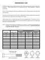
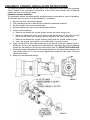
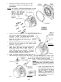
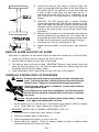
NOTE: If the ring gear was separated from the gear housing (12,000
lb. models only) a new gasket should be installed there
also. See Figure 5.
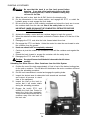
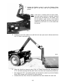
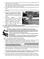
i. While keeping the felt marks lined up,
bolt the gear housing back onto the
drum support. Torque the socket head
bolts to 100--120 Lb.--in.
M9606--41
Figure 5.
NOTE:
The gear housing
may need to be lined--up
before bolting down. For housing to line--up properly, it may be necessary to slightly rotate
the ring gear inside the gear housing. Also, the detent assembly can be temporarily removed,
but must be installed before bolting down the gear housing. See Figure 5.
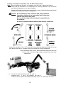
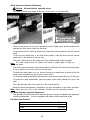
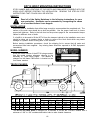
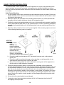
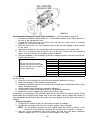
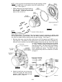
j. Bolt the clutch lever onto the clutch shaft using a 3/8” flat washer and 3/8NC hex nut.
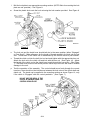
(See Figure 6) The position of the clutch lever on the clutch shaft may be adjusted for
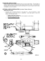
different control locations, but the WARN supplied decal can only be used if the clutch
is in the “Engaged” position with the control pushed
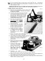
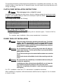
in. Figure 7 shows a typical installation where the
decal can be used. The clutch lever should always
travel through a 135_ arc from “Engaged to “Free
Spool” positions as shown. The lever must also
travel symmetrically about the centerline as shown
in Figure 7.
M9606--42
Figure 6.
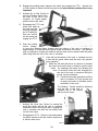
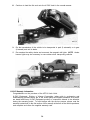
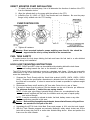
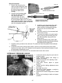
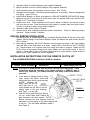
k. Attach the ball joint rod end onto the
clutch lever using the three 3/8” flat
washers, 3/8NC Hex head nut and
bolt as shown in Figure 8.
A13
Figure 7.
M9606--43