1
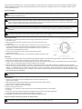
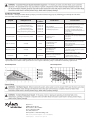
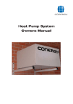
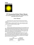
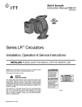
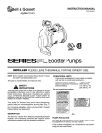
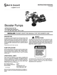
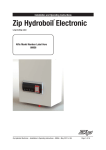
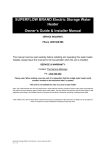
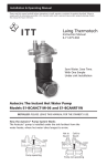
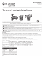
INSTRUCTION MANUAL
6-71-075-110
REVISION A
The ecocirc® auto/vario Series Pumps
Unpacking
When unpacking the unit inspect carefully for any damage that may have occurred during transit. Check for loose, damaged, or
missing parts. Do not attempt to assemble or operate pump if any parts are missing or damaged.
General Safety Information
1. Know the pump application, limitations and potential hazards.
WARNING: Pump should only be used with liquids compatible with pump component materials. Do not use to pump flammable or explosive fluids such as gasoline, fuel oil, kerosene, etc. Do not use in flammable and/or explosive atmospheres.
CAUTION: These pumps have been evaluated for use with water only. For your protection always wear proper clothing, eye
protection, etc. in case of any malfunction. For proper handling techniques and precautions, contact your supplier,
insurance company and local agencies (fire dept., etc.). Failure to comply with this warning may result in personal injury and/
or property damage.
2. Ensure that the power source conforms to the requirements of your equipment.
3. Disconnect power before servicing. If the power disconnect is out of sight, lock in the open position and tag it to prevent
unexpected application of power. Failure to do so may result in a fatal electric shock!
4. Release all pressure within the system before servicing any component.
5. Drain liquids from the system before servicing.
6. Personal Safety:
a. Wear safety glasses at all times when working with pumps.
b. Keep work area clean, uncluttered, and properly lighted. Replace all unused tools and equipment.
c. Keep visitors at a safe distance from the work area.
d. Make workshop childproof with padlocks, master switches and by removing starter keys.
7. The motor is designed to be used in a clean dry location with access to an adequate supply of cooling air.
8. When wiring an electrically driven pump follow all electrical and safety codes.
9. Single phase motors: All units are supplied with 115 volt, single phase motors.
10. All wiring should be performed by a qualified electrician.
WARNING: Do not handle a pump or pump motor with wet hands or when standing on a wet or damp surface or in water.
Australia
This pump must be installed in accordance with AS3500
InstallationÉ
The pump should not be used in flammable or explosive atmospheres. For installations where property damage might result from an
inoperative or leaking pump, provide a drip pan to collect leakage. Failure to follow any warning can result in personal injury and/or
property damage.
1. Support the piping independently of the pump. B&G pumps are lubricated by the pumped fluid. How they are mounted and
the condition of the water in the system are important. THOROUGHLY CLEAN and FLUSH the system before installing the pump. If
the fluid contains a high level of dissolved solids such as dirt, sediment, or products of corrosion, a strainer and/or filter should be
installed at least 12” before the inlet to the pump.
Mounting
For installation purposes the arrows on the pump housing indicate the
direction of water flow through the pump. Check to make sure the pump
is adequately supported and that neither the pump or the piping is
stressed. Install the pump at a point closest to the highest static pressure
point, but above the absolute lowest point in the system to avoid dirt and
sediment build-up. If required by application and code, install a safety
relief valve to protect against over temperature and pressure. Do not
mount with the motor above the impeller. This can cause the pump to run
dry leading to premature failure of the pump which voids the warranty.
Fig. 2
Electrical
These instructions must be followed to reduce risk of electrical shock. All work should be performed by a qualified electrician and in
accordance with the current national and local electrical codes and regulations. Consult the nameplate for electrical data. The
motor is protected. Make certain that a properly sized circuit is available. Wire size should be based on the current
carrying (amp) capacity of the conductor. The pump must be grounded in accordance with the current national and local codes.
Ground wire should be copper with a current capacity at least equal to that of the wire carrying power to the pump. Observe all
minimum code requirements for your jurisdiction. Isolation valves are recommended for both sides of the pump. Valves should be
positioned to avoid leakage onto the motor and electrical compartment. All elbows, tees, and sharp bends in the piping should be
installed sufficiently upstream or downstream of the suction and discharge ports. Avoid welding or soldering close to the pump,
which could cause damage to the unit. After installation, the end product must comply with the relevant product standard. Product
standard regulations must be observed during fitting and electric installation. Installation and electric connections shall be carried
out by professionals only.
Electrical SafetyÉ
WARNING: - Electrical Shock Hazard - Electrical connections are to be made by a qualified electrician in accordance with all
applicable codes, ordinances and good practices. Failure to follow these instructions could result in serious personal injury,
death and/or property damage.
WARNING: - Electrical Grounding Hazard - Adequate electrical grounding is required for the safe operation of B&G Pumps.
Ground the pump back to the service using a copper conductor at least the size of the circuit connectors supplying the
pump. Connect the ground wire to the ground terminal in the wiring compartment. Failure to follow these instructions could
result in serious personal injury, death and/or property damage.
WARNING: - Risk of Electric Shock - If this pump is supplied with a grounding conductor and grounding-type attachment
plug, to reduce the risk of electric shock, be certain that it is connected only to a properly grounded, grounding-type
receptacle.
WARNING: - Risk of Electric Shock - Do not install this pump in swimming pool or marine areas. Failure to follow these
instructions could result in serious personal injury, death and/or property damage.
Wiring InstructionsÉ
1. Loosen the screw securing the motor cover (wiring compartment), and remove
the screw & cover.
2. Attach the appropriate size connector to one of the holes in the side of the
conduit box.
3. Using a minimum size of 14 AWG copper electrical wire (refer to your local code
for wiring instructions), wire the motor to a single phase power source that
matches the electrical rating on the pump nameplate. See Fig.3. Use the size of
electrical wire as dictated by local code.
4. Connect the ground wire to one of the ground screws inside the
conduit box. See Fig. 3.
5. Make sure electrical connections are secured before replacing the motor cover.
Fig. 3
Operation
1. Completely fill and pressurize the system before operating the pump. Do not start the pump until the system has been filled.
Make sure the isolation valves are fully open and that there is water in the pump.
2. Purge air from the system prior to operating the pump. These two steps are very important. The pump should never be allowed to
run dry. This can severely damage the pump and will void the warranty.
3. Operate the pump for approximately 10 minutes at full speed (speed 7 on the dial) to purge any remaining air in the system. It
may be necessary to open a discharge valve, port and/or fixture to ensure that the air has been purged. The pump should be running
quietly. If a “gurgling” noise is present it may mean there is still air in the system. Turning the pump on and off several times will
generally clear the remaining air. If this “gurgling” noise persists, recheck the system and re-purge the air. System and pump should
now operate quietly and efficiently.
WARNING: Ensure that the unit is disconnected from the power source before attempting to service or remove any
components.
MaintenanceÉ
1. Since the rotor/impeller unit (see exploded views) is the only moving part, its
replacement is simple.
2. After the power has been disconnected using a counter clockwise motion remove
the screw ring housing to motor connection.
3. Remove the “O” ring from the pump housing.
4. Remove and replace the rotor.
5. Replace the “O” ring with a new one and reverse the disassembly procedure to reassemble
the pump.
6. Since these units are self lubricated by the pumped fluid, they never need external lubrication.
7. Pump should be drained when subjected to freezing temperatures.
8. If provided, the suction line strainer should be cleaned at regular intervals.
Removal of Pump From Existing System For Replacement
WARNING: - Electrical Shock Hazard - Disconnect and lockout the power before servicing. Failure to follow these
instructions could result in serious personal injury, death and/or property damage.
Trouble Shooting Chart
LED Indicator: Solid green LED indicates pump is powered and functioning properly. If flashing green LED please follow the
Corrective Actions for the errors below.
Symptom
LED Sequence Code
LED Sequence
Code Error
Intermittent Operation
1x Long, 4x Short
1x Long, 3x Short, 1x Long
1x Long, 2x Short, 1x Long, 1x Short
1X Long, 2x Short, 2x Long
1x Long, 1x Short, 1x Long, 2x Short
1x Long, 1x Short, 1x Long, 1x Short, 1x Long
Run Error #1
Run Error #2
Run Error #3
Run Error #4
Run Error #5
Run Error #6
1. Improperly Wired
2. Foreign object in impeller and housing
3. Overheated pump electronics
1 . Leak, Obstruction, or kink in suction line
2 . Suction line closed
3. Pump is worn
Possible Causes
Pump will not prime
1x Long, 1x Short, 2x Long, 1x Short
Dry-Run Error
Little or no discharge
Solid Light
No Error
1.
2.
3.
4.
Noisy pump operation
Solid Light
No Error
1. Air trapped in housing
2. Rotor bearing worn
3. Debris in housing
No Operation
No Light
Not Powered
Corrective Action*
Housing not filled with water
Suction piping too small
Total head too high
Impeller plugged
1. Blown Fuse or open circuit breaker
2. Loose or broken wiring
1. Check Motor wiring diagram
2. Disassemble pump, remove object, and clean
motor separating wall and impeller
3. Disconnect the power to the pump and let
the pump cooled down to ambient room
temperature. Check the fluid’s temperature for
proper setting.
1. Repair as necessary.
2. Open, then reset the pump by unplugging power
to the pump
3. Replace parts.
1. Properly prime housing
2. Increase to pump inlet size or one size larger
3. Reduce discharge head
4. Disassemble pump and clean motor separating
wall and impeller
1. Check pump prime, also turn pump on and off
several times to bump air pocket out of pump
2. Replace rotor assembly
3. Dissemble pump and remove debris
1. Replace fuse or circuit breaker after reason for
overload has been corrected
2. Tighten connections, repair wiring
* If the LED sequence code continues after all corrective actions have been verified and applied, please contact your local B&G
representative for assistance and report the run error sequence when the pump is returned for a warranty replacement.
auto Pump Curve
vario Pump Curve
vario Pump Curves
1
2
3
4
5
6
7
Setting 1
Setting 2
Setting 3
Setting 4
Setting 5
Setting 6
Setting 7
1
Xylem Inc.
8200 N. Austin Avenue
Morton Grove, Illinois 60053
Phone: (847) 966-3700
Fax: (847) 965-8379
www.xyleminc.com/brands/bellgossett
Bell & Gossett is a trademark of Xylem Inc. or one of its subsidiaries.
© 2012 Xylem, Inc. 6-71-075-110A July 2012
2
3
4
5
6 7
1
2
3
4
5
6
7
Setting 1
Setting 2
Setting 3
Setting 4
Setting 5
Setting 6
Setting 7