1
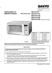
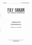
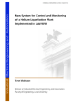
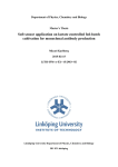
•
OPERATING AND SERVICE MANUAL
MODEL 4318
POWER METER
•
SERIALS PREFIXED: 301-. 233-. & 221-
Copyright
H~WLETt.PACKARD COMPANY
1962
1501 PAGE MILL ROAD, PALO ALTO, CAlifORNIA, U.S,A.
•
01370·2
Printed: MAR 1964
.section r
Figure 1-1
ModeJ 431.l3
f
Figure 1-1. MOdel 48113 Power Meter
f
01370_1
Section I
Paragraphs 1-1 to 1-4
Model 431B
SECTION I
GENERAL INFORMATION
electrically isolated. One thermistor is used to
absorb rf power; the other is used. to provide temperature compensation. Thus, the thermal drift problems
normaUy associated with the thermistor-power meter
arrangement have been greatly reduced. A single
setting of the ZERO control on the most sensitive
power range is maintained within 1% for all higher
1-1. DESCRIPTION.
1-2. The!f;j; Model 431BPower Meter, with!f;j;temperature compensated thermistor mounts, measures rf
power from 10 micl'owatts (-20 dbm) to 10 milliwatts
(+10 dbm) in the 10-mc to 40-gc frequency range.
Direct reading accuracy of the instrument is ±3% of
full scale. Instrument specifications are given in
table 1-1.
power ranges.
1-3. The design of the Model 431B and its thermistor
mount, results in almost complete freedom from
1-4. The temperature compensated thermistor
mounts used with the instrument are specifically designed for !f;j; Model 431A/B Power Meters. Coaxial
and waveguide thermistor mounts cover the 10-mc to
40-gc frequency range. Table 1-2 gives thermistor
mount operating frequency, mount configuration, and
operating resistance.
measurement- error caused by ambient temperature
changes.
The instrument incorporates two selfbalancing bridges with one arm of each bridge being
a thermistor. The two matched thermistors, both
located within the mount, are thermally coupled, but
Table 1-1. Specifications
Weight:
Net 8 Ib (3.63 kg) with cover and cables 11-1/2 Ib
(5.44 kg) Including battery; shippingapprox.13lb
(5.9 kg)
Instrument Type:
Automatic, self-balancing for temperature compensated mounts
Power Ranges:
7 ranges with full scale readings of 10, 30, 100
and 300 Ii w; 1, 3 and 10 mw. Also calibrated In
dbm from -20 to +10.
Accessories FUrnished:
5 ft (1.5 m) cablefor!f;j;temperature-compensated
thermistor mounts. 7-1/2 ft(2.3 m) power cable,
NEMAplug.
Exiernal Bolometer:
Temperature-compensated thermistor mounts
required for operation (!f;j; 478A and 486A series).
Accessories Available:
431A-95B Rechargeable Battery Pack for field
Installation.
Accuracy:
±3% of full scale from +20'C to+35'C, ±5% of full
scale from O'C to +55'C
!f;j; Models 478A and 486A Thermistor Mounts
!f;j; Model 8402A Power Meter Calibrator
!f;j; Model HOl-8401A Leveler Amplifier
Zero Carry-Over:
Less than 1% of fuU scale when zeroed on most
se~sitlve range
,
Recorder/Voltmeter Output:
Phone jack on rear with 1 rna maximum into 1000
ohms ±10%; one side grounded
Calibration Input:
Binding posts on rear for calibration of bridge with
!f;j; 8402A Power Meter Calibrator or precise dc
standards
Power Supply:
115 or 230 volts±10%, 50 to 1000 cps, 2-1/2 watts
Dimensions:
6-17/32 in.(166 mm) high, 7-25/32 in. (198 mm)
Wide, 12-1/2 in. (318 mm) deep
01370-2
Options:
01. Rechargeable battery installed, provides up
to 24 hours continuous operation,
•
02. Rear input connector wired In parallel with
front panel Input connector,
10. With 20 foot cable for 100 n or 200 n mount,
11. With 50 foot cable for 100 n mount,
12. With 100 foot cable for 100 n mount,
13. With 200 foot cable for 100 n mount,
21. With 50 foot cable for 200 n mount,
22. With 100 foot cable for 200
23. With 200 foot cable for 200
n mount,
n mount.
1-1
Section I
Paragraphs 1-5 to 1-11
Model 431B
Table 1-2 Model 431B Thermistor Mounts
Type
Coaxial
alone. In addition a jack in series with the panel meter
permits digital or chart recording of measurements,
operation of alarm or control systems and use In a
closed-loop leveling system.
Frequency
Range
Operating
Resislance
In ohms
10 mc to 10 gc
200
~ S486A
2.6 to 3.95 gc
100
~ G486A
3.95 to 5.85 gc
100
~ J486A
5.3 to 8.2 gc
100
~ H486A
7.05 to 10.0 gc
100
~
100
~ M486A
8.2 to 12.4 gc
10.0 to 15.0 gc
100
1-8. INSTRUMENTS WITH OPTIONS.
~P486A
12.4 to 18.0 gc
100
18.0 to 26.5
200
26.5 to 40.0
200
1-9. The options available with the Model 431B
Power Meter are given in table 1-1. The thermistor
mount cable options require modification and recallbration of the Model 431B.PQwer MllJer. The recallbration procedures for the cables are given in section
V, Maintenance, under Oscillator Frequency Adjustment (paragraph 5-58) and Coarse Null Adjustment
(paragraph 5-63).
Waveguide
~ 478A
~
X486A
K486A
~ K486AC*
~ R486A
~R486AC*
1-6. ACCESSORIES.
1-7. Two accessories are supplied with the Model
431B Power Meter: a 7-1/2-foot, detachable power
cable and a 5-foot cable that connects the thermistor
mount to the Model 431B. Thermistor mounts are
available (see table 1-2) but not supplied with the
Instrument. A rechargeable battery with Installation
kit is also available. A list of supplied and available
accessories Is given in table 1-1, SpeCifications.
* With circular contact flange adapter
1-10. INSTRUMENT IDENTIFICATION.
1-5. The Model 431B has provisions for. using the
dc substitution method of measurement and for checking calibration accuracy of the power meter. The dc
substitution method of measurement which requires
other equipment provides greater power measurement
accuracies than can be obtained by the power meter
1-2
1-11. Hewlett-Packard uses a two-section eight-digit
serial number (000-00000). If the first three digits of
the serial number on your instrument do not agree
with those on the title page of this manual, change
sheets supplied with the manual will define differences
between your instrument and the Model 431Bdescrlbed
In this manual.
01370-2
Section 1II
Paragraphs 3-1 to 3-16
Model 431B
SECTION III
OPERATION
3-1. INTRODUCTION.
3-2. The r$ Model 431B Power Meter measures rf
power ranging from .01 to 10 milliwatts with power
meter accuracy of ±3%. Since the zero carries over
within 1%, accuracies of at least ±4% can be obtained
on any range by a single zeroing on only the lowest
range.
procedure given in figure 3-2. This wlll check for
normal operation from ac primary power. Ifperformance is normal proceed to step b.
b. Set POWER to BATTERY CHARGE:
the AC
CHARGE lamp wlll glow. Allow Model 431Bto charge
the battery for 48 hours. This wlll allow the battery
to obtain a full charge.
3-3. MECHANICAL ADJUSTMENT OF
METER ZERO.
3-4. The procedure for performing the mechanical
adjustment of the meter zero is given in section V,
paragraph 5-54.
c. After the recharge interval, set POWER to
BATTERY ON. Since battery is now fully charged,
you should be able to zero-set and null the meter
(figure 3-2). If not the battery or battery charging
circuit Is at fault. Refer to Battery and Charging
Checks paragraph 5-40.
3-5. CONTROLS AND INDICATORS.
3-6. The front and rear panel controls and connectors
are explained in figure 3-1. The explanations are
keyed to corresponding controls and indicator on the
drawing of the front and rear panels of the instrument
provided with the figure.
3-15. MAJOR SOURCES OF ERROR, MICROWAVE
POWER MEASUREMENTS.
3-7. OPERATING INSTRUCTIONS.
3-8. Figure 3-2, Turn-On and Nulling Procedure,
and figure 3-3, DC SUbstitution Technique, give stepby-step instructions for operating the Model 431B. In
figure 3-2, each step is numbered to correspond with
numbers on the accompanying drawing of the power
meter.
3-9. BATTERY OPERATION.
3-10. The following applies to power meters having
a factory or a field-installed rechargeable nickel-cadmium battery. See figure 3-1, Turn-On and Nulling
Procedure, for step-by-step instructions for operating
the Model 431B from a battery.
3-11. BATTERY CHARGING TIMES.
3-12. The battery used In the Model 431B requires
two hours of charge time for one hour of battery
operation. When the battery is fully charged, the
Model 431B can be continuously operated for 24 hours
with 48 hours of charge time. However, it Is recommended that battery operated instruments be operated
for eight hour periods with a 16 hour recharge time.
This makes the Model 431B available for portable
use daily, yet maintains the battery at full charge.
3-13. BATTERY CHARGE CHECK.
3-14. Under normal conditions, a fully charged
battery wlll start at approximately 27 volts and drop
to about 22 volts after 24 hours of continuous use at
room temperature.
a. Connect the Model 431B to ac primary power.
Set POWER to AC and perform the turn-on and nulling
01370-2
3-16. In microwave power measurements, the following are the major sources of error: 1) mismatch error
or tuner loss (when a tuner isused to tune out mismatch
error), 2) bolometer mount efficiency, 3) substitution
error, 4) instrument error and 5) error due to the
unilateral properties ofa thermistor. Thus five errors
must be known if accurate power measurements are
to be obtained. Expressed mathematically:
Total measurement error =
mismatch (or tuner) loss + calibration factor +
instrument error + error due to the unilateral
properties of a thermistor
a. Mismatch Loss. Unless the mount and rf source
are perfectly matched to the transmission system, a
fraction of incident power is reflected and does not
reach the thermistor. Since there generally is more
than one source of mismatch in a microwave meas-
urement system and the resulting error signals interact, loss can riot be calculated from the swr figure, it
can only be expressed as lying between two limits.
Limits of mismatch loss generally are determined by
means of a chart such as the Mismatch Loss Limits
chart included in each of the thermistor mount
Operating Notes. A tuner such as the t$ Model 872A
or 870A can be used to minimize loss, although the
tuner itself wlll introduce some loss.
b. Bolometer Mount Efficiency and SUbstitution
Error. Not all the rf power applied to the mount is
used to heat the rf thermistor. Some of it is absorbed
by the other elements in the mount, such as the walls
of the rf chamber, the heat Sinks, the leads, etc. SUbstitution error results because rfpower does not affect
the thermistor to the same degree as dc power. SUbstitution error and mount efficiency are often combined
forsimpllcity of measurement into what is termed
"calibration factor". Typically, the calibration factor
of the Model X486A waveguide mount Is 97% to 98%.
3-1
Section 1II
Figure 3-1
Model 431B
..
IIlun($jlUCIiII
o
"~le
1'0"£11; WEHR
T/I£I'IM!SIOR WoolfT
DC CALIBRATION'
a
SUBSTITUTION
liNE
VOl..TAGE
PO~ER
8
1. POWER: The POWER switch sets up connections
to the selected power sources or to the battery
charging circuit. When the power switch is in
the AC position, externally supplied 115 or 230
volts is applied to the instrument. If the instrument contains a battery, a trickle charge is
applied to maintain the battery at full charge.
With POWER at BATTERY ON, a 24-vdc battery
within the instrument supplies primary power
to the instrument. With POWER at CHARGE,
115- and 230-volt power is used to charge the
battery (16 to 24 hours is required to obtain
full battery charge). The instrument is inoperative in this position. Note: Batteries
are installed at the factory for option 0linstruments only.
2. RANGE: The RANGE switch can be set for full
scale power readings from .01 to 10 milliwatts
in seven steps. It also includes a NULL position which, in conjunction with the adjacent
null screwdriver adjust, insures that the metering bridge is reactively balanced.
3. THERMISTOR MOUNT:
The THERMISTOR
MOUNT connector is a female receptacle that
accepts a specially-made cable which is supplied
with the instrument. The cable connects the
mount thermistors into their respective bridges
within the power meter.
9
4. MOUNT RES: This two - position slide switch
sets the power meter to accommodate thermistor mounts of 100- or 200-ohm nominal
resistance.
·5. ZERO and VERNIER: The ZERO control
coarsely sets the meter pointer near zero; the
VERNIER control is a more exact adjustment
which sets the meter pointer on zero.
6. In Option 02 instruments only, mount connector
wired in parallel with front - panel connector.
Two mounts cannot be connected simultaneously.
7. RECORDER: The RECORDER input is a grounded
telephone jack for monitoring the current which
operates the Model 431B meter.
8. DC CALIBRATION & SUBSTITUTION: This
terminal permits application of known direct
current to the rf bridge. The power reading
obtained with the accurately known dc power
applied is then compared with the reading obtained when rf power was applied. The dc substitution technique is used both to calibrate the
431B and to increase the accuracy of power
measurement.
9. LINE VOLTAGE: The LINE VOLTAGE switch,
SI, is a two-position slide switch that selects
the mode of ac operation. The line voltage for
which the instrument is set to operate appears
on the slider of the switch. A 15/100 slow-blow
fuse is used for both 115 and 230 volt operation.
Figure 3-1. Front and Rear Panel Controls and Indicators
3-2
01370-2
Model 431B
Section III
Figure 3-2
.
o
•
o
ZERO
4318 POWER NETER
RANGE
POWER
Of'
VERNIER
IilI ,OI.W.1 .5 I
a 10
01101 -to-.5 -1O'f 0 U +10
,I.e
TIiERMISTOR
MOUNT
4
"
.
eMU&[
1. Connect thermistor mount and cable to the
THERMISTOR MOUNT. ~ thermistor mounts
and their frequency ranges are given in table
1-2, Model 431B Thermistor Mounts.
Note
When possible, the Model 431B should be
zeroed and nulled with the power source to
be measured connected to the thermistor
mount. If this is not possible, anda coaxial
thermistor mount is used, terminate the
rf input into a 50-ohm load. Power source
should be off while zero and null-setting
the Model 431B Power Meter.
2. Set MOUNT RES to match thermistor mount
resistance (100 or 200 ohms).
3. Set RANGE to .01 MW.
4. Set POWER to AC; AC & CHARGE lamp will
glow. If instrument is battery-operated, rotate
POWER to BATTERY ON.
5. Adjust ZERO control for 25 to 75% of full scale
on meter.
6. Rotate RANGE to NULL and adjust null screwdriver adjust (adjacent to NULL on RANGE
switch) for a minimum reading.
7. Repeat steps 5 and 6 until NULL reading Is
within NULL region on the meter.
Note
If instrument is battery-operated and you
are not able to zero the meter, or if meter
pointer fluctuates rapidly, battery needs
recharging. Refer to paragraph 3-11.
8. Set RANGE switch to the power range to be used
and zero-set the meter with ZERO and VERNIER
controls.
Note
Zero-set accuracy of 1% can be obtained
by zero setting the meter on the most
sensitive range (.01 MW) only, and assuming the meter is properly zeroed on all less
sensitive ranges. For maximum accuracy,
zero set the meter on the range to be used.
9. Apply rf power at the thermistor mount and
read power on Model 431B meter. Power is
indicated on the meter directly In mw or dbm.
Note
This instrument is accurate to wlthin±3%.
Accuracy to ±1%, or better, is possible
using the dc substitution technique described in figure 3-3. See also paragraphs
3-15 and 3-17.
Figure 3-2. Turn-On and Nulling Procedure
01370-2
3-3
Section III
Figure 3-3
Model 431B
POWER SUPPLY
o-300vdc
0-2oma
c6lMODEL 4318
POWER METER
(~7I1A)
Q
10K, 10%, lOW
1. With power supply turned off, connect the
Model 431B as shown above.
2. Set the Model 431B for normal operation on the
appropriate range using the procedure given ill
figure 3-2.
CAUTION
Never apply more than 20 ma dc to the DC
CALIBRATION & SUBSTITUTION terminals of the Model 431B.
6. Read the voltmeter which monitors the substitu-
3. Apply rf power at the thermistor mount and
note and record the reading of the Model 431B
meter. This Is the reference for the substitution measurement.
Note
A second digital voltmeter, In parallel
with a 1000-ohm (±10%, 1 watt) resistor,
connected In series with the RECORDER
output of the Model 431B will increase
accuracy of reference duplication.
4. TUrn off, or disconnect, the rf source.
6. Turn power supply on; adjust the output voltage
of the power supply until the reference of step 3
is duplicated. 1). potentiometer arrangement
may be substituted for the adjustable power
supply. However, at least 10,000 ohms must
remain In series with the supply.
tion current. - The voltmeter readlng- can be
interpreted as current in milliamperes because
the voltage is measured across 1000 ohms.
This current Is Idc'
7. Calculate power In mw from the expreSSion
Power (MW) =
where Rd = operating resistance of the termIstor (100 or 200 ohms)
and Idc = substitution current In milliamps
(from step 6)
9. To minimize error due to drift in either the
reference or substituted power level, steps 1
through 6 should be repeated.
Figure 3-3. DC SUbstitution Technique
3-4
01370-2
Mpdel431B
Section III .
Paragraphs 3-17 to 3-26
c. Instrument Error. This is the inability of the
power meter to accurately measure and Interpret the
Information. available at the thermistor element. In
specifying the accuracy of a power meter, instrument
error is the figure usu·allygiven. Forthe Model 431B,
instrument errOr is ",3% of full scale, 20'C to 35·C.
This error can be reduced by special techniques such
as the dc sUbstitution method discussed in para. 3-17.
d. Error Due to the Unilateral Properties of a
Thermistor. The thermistor used in conjunction with
the Model 431A/B.exhiblts unilateral properties which,
when tlle source of power is a dc current, causes a
slightly different indication of power than is obtained
by the calculation of I2R. Thus the dc power required
to produce a reading on the Model 431A/B Power
Meter is not the same as the rf power required to
produce the same reading on the Model 431A/BPower
Meter .. The maximum error produced from this source
of error is±0.3 Ilwatls, typical error Is ±O.lllwatl.
Since the order of magnitude of this error Is small
(0.3 IlWatl) it need be minimized only on the two most
sensi.tlve ran/jes of the Model431A/B Power Meter.
Refer to the I!!fJ Model 8402A Power Meter Calibrator
manual for p~ocedure used to minimize this error.
3-17. POWER METER ACCURACY OF 1% OR
GREATER USING THE DC SUBSTITUTION
METHOD.
3-1S. Highly accurate instruments are available for
measuring· direct current. Thus, where optimum
accuracy is required, there is considerable advantage
in using a technique where the rf measurement is
used only as a reference and the determination of rf
power is based on precise dc measurements. In
general the technique involves:
a. Applying rf pOWer to the Model 431B In the usual
manner, and noting the resulting meter indication for
use as a reference.
b. Removing the rfpower and applying sufflcient dc
at the DC CALiBRATION & SUBSTITUTION terminals
to exactly duplicate the meter indication produced by
the rf power.
c. Using the value of dc which duplicated the reference In calculating rfpower.
3-19. Although the dc substitution technique is the
most accurate method.of measuring rfpower, there
are sources of error that must be considered. The
accuracy of the dc substitution technique depends
largely upon:
a. how precisely the reference is duplicated,
b. how accurately the value of the substituted dc is
known,
c. the. actual operating resistanceofthethermistor,
and
d. the actual ratio of current division In the rf bridge.
3-20. With precision components in the substitution
setup and careful procedure, error produced by the
Model 431B Power Meter can be reduced to 1% or less.
This is assuming nominal thermistor mount resistance
(100 or 200 ohms) and that half the applied dc flows
through the rf thermistor. The dc substitution tech"
nique using the Model· 431B is shown in figure 3-3.
3-21. EQUIPMENT USED FOR DC SUBSTITUTION.
3- 22. The <fj; Model 8402A Power Meter Calibrator
was specifically designed to be used for calibration
and dc SUbstitution measuremerlts of rf power .. In
addition, the instrumentwlll accurately measure the
operating resistance of the thermistor mount being
used. Use the procedures givenin the manual provided
with the <fj; Model 8402A Power Meter Calibrator to
perform the dc substitution measurements.
3- 23. Although the most convenient and accurate means
of applying the dc substitution technique is by using
<fj; Model 8402A Power Meter Calibrator, It is also
possible to accurately measure power using the dc
substitution technique with the arrangement shown in
figure 3-3. The digital voltmeter is used to monitor
the substitution current. .The power supply output and
voltmeter input are ungrounded to eliminate ground
currents.
3-24. ADDITIONAL APPLICATIONS.
3-25. At the RECORDER output,. the Model 431B furnishes a current (0 to 1 ina dc) which is proportional
to the power measured. This feature makes possible
a measurement system with more capability than
simply the indication of power on a meter. Some of the
more sophisticated measurement systems are shown
in block diagram· form in figures 3-4 through 3-8.
3-26. PERMANENT RECORD. Use oi" a ·recorder in
the measurement system is Indicated In figure 3 -4.
Resistance across the Model 431B RECORDER output
should be 1000 phms ±10% for optimum measurement
accuracy. Any type of recorder may be used with the
Model 431B; If Input resistance exceeds 1000 ohms,
use a shunt across the recorder input.
.
RF SOURCE
--
TEMPERATURE
COMPENSATED
THERMISTOR
MOUNT
( @; 418A. 486Al
.-
<fj;MODfl43IB
POWER
METER
JI02
RE.9.l?ROER
't
~
~IOOOCl
INPUT
RECORDER
80-S- 252
Figure 3-4. Making a Permanent Record
01370- 2
3-5
Section ill
Paragraphs 3-27 to 3-30
Model 431B
RECORDER
Rf SOURCE
-
TEMPERATURE
COMPENSATED
THERMISTOR
MOUNT
(1PJ 418A 486A)
-
J~
JJ
.OI J .I , I, IOMW
"-
rtl 1y ~3 3.3MWI~~
$MODH 4318
POWER
METER
••
1jJ UODEL405
DIGITAL
VOLTMETER
80-S-2~3
Figure 3 -5. Obtaining Increased Resolution
3-27. INCREASED RESOLUTION. Digital readout of
power to three decimal places can be obtained with the
arrangement shown in figure 3-5. The value of Rl Is
316.2 ohms ±.1% and Rt is 1000 ohms ±.1%. Correct
placement of the decimal in the readout is determined
by the setting of the power meter RANGE switch. On
the divider-switch arrangement at the voltmeter input
may be replaced by a single 1000-ohm .1% resistor.
With this arrangement, on the .01, .1, and 10 MW
ranges, power is read In the same way as when the
arrangement shown in figure 3-5 is used, decimal
placement being determined by the setting of RANGE.
On the .03, .3, and 3 MW ranges, however to obtain
the power readings the voltmeter indication must be
multiplied by the factor given in table 3-1.
Model 431B and its thermistor mount, such a leveling
system requires the 1jJ HOI-8401A Leveler Amplifier
and a directional coupler with good directivity such as
one of the 1jJ 752 series of waveguide couplers or 760
series of coaxial couplers. The output of the power
source is sampled by the coupler and applied to the
Model 431B. A dc signal, proportional to the power
sample, is fed (from the Model 431B RECORDER jack)
to the Leveler Amplifier. In the HOI-8401A the signal
from the Model 431B is compared to an internal reference voltage, and the difference is amplified and fed
back as a control voltage to hold output power constant.
3-29. MONITOR CONTROL SYSTEMS. By adding a
dc amplifier and relay circuit to the rf monitoring arm
of a system, the dc Signal provided by the Model 431B
can be used to actuate alarm or control circuits. Arrangement of equipment to provide an alarm or control
system is shown in block diagram form in figure 3-7.
Table 3-1. Voltmeter Readout to Power Multipliers
Range
3-30. DETERMINING INSERTION LOSS OR GAIN AS
A FUNCTION OF FREQUENCY. Arrangement of a
system to obtain information on insertion loss or gain
as a function of frequency is indicated in figure 3-8.
Initially, the device under test is not connected into the
system; connect the thermistor mount directly to the
sweep oscillator. Set the sweep oscillator for the band
of interest, and record variations in amplitude as
frequency is swept; tliis curve is the reference. Next,
insert the device under test between the sweep
oscillator and the thermistor mount, and again record
frequency response.
The difference between the
second reading and the reference, at anyone frequency,
is the Insertion loss or gain of the device at that
frequency.
Multiplier
.03MW
0.0316
.3
0.316
3
3.16
3-28. LEVELER. Figure 3-6 is a block diagram of
a closed-loop control circuit for maintaining output
power at a constant level. It is recommended for use
in leveling the output of various types of1jJ microwave
eqUipment such as bwo sweep oscillators, twt microwave amplifiers, and rf generators. In addition to the
RECORDER
TEMPERATURE
COMPENSATED
THERMISTOR
1jJ MOUNT
418A.486A
-
--
1jJMODH 4318
POWER
METER
:!..102
1y
INPUT
t
AMPLITUDE
MODULATION
INPUT
-
1jJHOI-840IA
LEVELER
AMPLifiER
-
OUTPUT
I
Rf
POWER
SOURCE
--+
DIRECTIONAL
COUPLER
--+
LOAD
+ - CONTROL VOLTAGE (NEGATIVE fEEDBACK)
--
BD S 254
Figure 3-6. Leveler Setup
3-6
01370-2
Model 431B
Sectiohm
Figures
.
.
r-
JI02
TEMPERATURE
COMPENSATED
THERMISTOR
MOUNT
~418A.488A
t
..
.
--
~MODEl43IB
POWER
METER
....
RE~DER
rrn
DC
AMPlifiER
looon
.
3~7and3"8
--
--
RELAY
ALARM.
CONTROL.
PROTECTlVE,OR
CORRECTIVE ..
DEVICES
90-5-255
,
Rf SOURCE
--=-.
COUPLER
-+
LOAD
Figure 3 -7 . Monitoring Control Systems
Rf
SWEEP
OSCILLATOR
Rf
OUTPUT
- --"
SWEEP
OUTPUT
01370-2
MICROWAVE
DEVICE
-
~
TEMPERATURE
COMPENSATED
THERMISTOR
UNT
rttIJ M9
4 8A.486A
--
~MODEL 4318
POWER
METER
RECORDER
J~
cry
Y
INPUT
L
~IOOO~
X-Y RECORDER
_.
.
X
INPUT
-+.
--
80 S 256
Figure 3-8. Determining Insertion Loss or Gain
3-7
Section IV
Figure 4-1
Model431B
,
/
10
I KC
f
I
~
10lC
OSCILLATOR
mUF1ER
0108-0111
,..-----,
DETECTION I
THERMISTOR I
ICROW~
POWER
M
J'17
'"
:
Ro
'="
TlO!
I
I
I
I
I
I
I
I
I
IMOUNT
RES
I
'"
I
Rc
~
I
I
; ~NULL
I"
CURRENT
a
,,
10lC
AMPUflER
0101-010)
"
7C
TI02
iY11
I
I
I RANGEl
SI02
SYNCHRONOUS
DmCTOR
CRIOI-CRI04
I
I
~,
I
I
loe
........ - ....
fEE081Cl
CURRENT
CENERATOR
OIOT
~
0
I-+-
0---, , ,
~
\/
VERNIER
loe
I.
I
I
I
I
~0
L ___ -_J,J. ADJ,
CONTROL
J tOKe
• ,
I
I
I
I
I
I
I
I
I
,
I
o ',JI'
'1W :
I~
LEGEND
SIOI
I
I
I
I
=JII(
I
.~
I POWER I
/
,OS2
1151230VAC
5O·IOOOCPS OR
-24VOC
RmlllED
POIER
SUPPlY
+1.5VOC
-18VDC (REG)
-25VOC (REG)
DlffERENTIIl
AMPlifiER
010410105
" ,
" .......... ~"
,
'"I ' ,
I
mOBIClCURRENTSOUARED
CENERATOR
0106
I
...........
MIDI
I /'
I.
I [~EJ03D
JI02
I
RIBI
1000
~
_L
OPTIONAL BATTERY
Figure 4-1. Block Diagram
4-0
01370-2
Model 431B
Section IV
Paragraphs 4-1 to 4-11
SECTION IV
THEORY OF OPERATION
4-1. OVERALL DESCRIPTION.
4-6. CIRCUIT DESCRIPTION.
4-2. Figure 4-1 is a block diagram which Shows the
Model 431B Power Meter and its associated thermistor
mount. The thermistor mount contains two thermistor
elements (Rd and R c)' Thermistor element Rd absorbs
the rf power applied to the mount; thermistor element
Rc converts the applied rf power to a meter indication
4-7. RF BRIDGE CIRCUIT.
4-8. A simplified schematic diagram of the rfbridge
circuit is shown in figure 4-2. The rf bridge circuit
consists ofthe rfbridge and lO-kc oscillator-amplifier.
The rf bridge includes thermistor Rd, the secondary
winding of TIOI, resistors RI02 andRI03, the MOUNT
RES switch, SIOI, and capacitance represented by Ca
and Cb' The rf bridge and 10 kc oscillator-amplifier
are connected in a closed loop (the detection loop) which
provides regenerative feedback for the oscillatoramplifier. This feedback causes the 10 kc oscillatoramplifier to oscillate.
and provides compensation for ambient temperature
changes at the thermistor mount.
4-3. The power meter circuitry incorporates two
bridges which are made self-balancing by means of
separate feedback loops. Regenerative (positive) feedback is used in the detection loop; degenerative feedback in the metering loop. One thermistor element is
used in one arm of each of the self-balancing bridges.
In the detection loop, the 10 kc oscillator-amplifier
supplies enough 10 kc power (110 kc) to bias thermistor
element Rd to the operating resistance which balances
the rf bridge. The same amount of 10 kc power is also
supplied to thermistor element Rc by the series-connected primaries of transformers TIOI and TI02.
4-4. When rf power is applied to thermistor element
Rd, an amount of 10 kc power equal to the rf power is
removed from thermistor element Rd by the selfbalanCing action of the rf bridge. Since the primaries
of TI01 and TI02 are series-connected, the same
amount of 10 kc power is also removed from thermistor
element Rc ' thus, the action which balances the rf
bridge unbalances the metering bridge. The metering
bridge loop automatically re- balances by substituting
dc power for 10 kc power. Since the 10 kc power
equaled the applied rf power, the substituted dc power
is also equal to the applied rf power. Instead of
metering the feedback current directly, which would
require the use of a nonlinear meter scale, an analog
current is derived which is proportional to the square
of the feedback. Since power is a square-law function
of current, the analog current thus derived is proportional to rf power, making possible the use of a
linear scale on the meter.
4-9. When the power meter is off, thermistor Rd is
at ambient temperature and its resistance is about 1500
ohms; the rf bridge is unbalanced. When the power
meter is turned on this unbalance of the rf bridge
causes a large error Signal to be applied to the 10 kc
oscillator-amplifier. Consequently maximum 10 kc
bias voltage is applied to the rf bridge. As this 10 kc
voltage biases Rd to its operating resistance (100 or
200 ohms) the rf bridge approaches a state of balance
and regenerative feedback diminishes until there is just
sufficient 10 kc bias power to holdRdat operating resistance.
This condition is equilibrium for the
detection loop.
4-10. With application of rf power, thermistor Rd's
resistance decreases causing the regenerative signal
from the rf bridge to decrease. Accordingly, 10 kc
power diminishes, the thermistor returns to operating
resistance and the detection loop regains equilibrium.
4-11. The MOUNT RES switch, SIOI, changes the
resistance arm of the rf bridge so that the bridge will
function with either a 100 or 200 ohm thermistor mount.
IOKe BIAS
TO METERING BRIDGE
TIOI
4-5. There is little drift of the power meter zero
point when ambient temperature at the thermistor
mount changes. If, for example, ambient temperature
at the mount increases, a decrease in electrical power
to the thermistors is required to hold their operating
resistances constant. The decrease, for both thermistors, is made automatically by the detection loop
(figure 4-1) which reduces 10 kc power. The amount
of dc power in the metering loop remains unchanged
however, and since this de power controls the meter
action, the am b i e n t temperature changes don a t
affect the meter indication. The compensation capability depends upon the match of thermistor temperature characteristics. When thermistor mounts are
built, the thermistors are selected to insure optimum
match of thermal characteristics.
01370-2
1
RI02
200.3
RES
Rd
'i"
: at
c.
Ie/I
RFI
I
SHIELD I
I ~
RF
I
I
I
I
t
Itoonl
SlOt
IMOUNT
f"""'lr
~-.--,
RI03
200.3
1200nl
L..vJ
.J,
I
tOKe
OUlllAlOR
AMPLIfiER
IOKe
EAROR
SIGNAL
~
..
Figure 4-2. RF Circuit
4-1
Section IV
Paragraphs "4-12 to 4-19
Model 43lB
4-12. METERING BRIDGE CIRCUIT.
FROM
4-13. A simplified schematic diagram ofthe metering
bridge circuit Is shown In figure 4-3. Operation of the
metering bridge circuit is similar to the rfbridge circuit. It uses the same principle of self-balancing
through a closed loop (metering loop). The major difference is that dc rather than 10-kc power is used to
rebalance the loop. The resistive balance point is
adjusted by the ZERO and VERNIER controls which
constitute one arm of the bridge. The MOUNT RES
switch (not shown in figure 4-3) which is mechanically
linked to both the rf bridge and metering bridge,
changes metering bridge reference resistance from
100 to 200 ohms. When the MOUNT RES switch is In
the 200-ohm position some of the feedback current is
shunted to ground through RlOl. This maintains the
12R function constant when mount resistance is changed
from 100 or 200 ohms. The switch also adds the
necessary reactance for each position.
4-14. The same 10 kc power change produced in the rf
bridge by rf power also affects the metering bridge
through the series connection of TlOl and T102 primaries. Although this change of 10-kc power has equal
effect on both the rf and metering bridges, it is initiated
by the rf bridge circuit alone. The metering bridge
cannot control lO-kc bias power, but the 10-kc bias
power does affect the metering circuit. Once a change
in the 10-kc bias power has affected (unbalanced) the
metering bridge, a separate, closed dc feedback loop
(metering loop) re-establishes equilibrium in the
metering circuit.
4-15. Variations in 10-kc bias level, initiated In the
rf bridge circuit, cause proportional unbalance of the
metering bridge, and there is a change in the lO-kc
error signal (SlO kc) applied tothe 10-kc tuned amplifiers in the metering loop. These error Signal variations are amplified by three 10-kc amplifiers, and
rectified by the synchronous detector. From the
synchronous detector the dc equivalent (Idc) of the
10-kc signal is returned to the metering bridge, and Is
monitored by the metering circuit to be indicated by
the meter. This dc feedback to the metering bridge
acts to return bridge to Its normal, near-balance
condition.
-
FROM
10KC
BIAS
RF BRIDGE
!(
0:
METERING
BRIDGE
.,',
I,OKC
,"
l
~
• TI02 •
--------...,
I:)0MPENSATION
;¥CI03
NULL
AOJ.
I
THERMISTOR :
IZEROI
IS'OKc , ~.
I
IVERNIERI
________ ...1I
J
L _
s
RF SHIELD
hoc
~
IOKe ERROR SIGNAL
-
SIOKC
-.,!;-
RECTIFIED
/
I
10KC
<-
WNW" ~ SYNCHRONOUS l'OKe
+
AMPlImRS
0101.101110)
OETECTOR
+
-
DC BIAS
'De
OC
AMPlifiER
010411G5
~
+
t
OC BIAS
CIRCUIT
0107
5D-5_116
Figure 4-3. Metering Bridge Circuit
4-2
e-
RF
~OG::E=-_.:.:10.:.:K.:.e-=8.::.'A:.:,S
CID3
o
,-
-,
I
I
NULL I
ADJ.
T
I
IRF
.SHIELD
I
_J
'--
IZERol
AND
I VERNIER
I
10KC
~
COMPENSATION
THERMISTOR
ERROR
SIGNAL
10KC
ANPLlflER
0101.102.10)
RI38
CRIOS
RIBI
Figure 4-4. Nulling Circuit
4-16. The reactive components of the metering bridge
are balanced with variable capacitor Cl03 and inductor
Ll02. Null adjust, C103, is an operational adjustment
and Ll02 is a maintenance adjustment. Null adjust
Cl03, Is adjusted with the RANGE switch in the NULL
position. A simplified schematic diagram ofthe NULL
circuit is shown in figure 4-4. The 10 kc signal is
taken at the synchronous detector, rectified by CRl05,
and read on the meter. The rectified signal contains
both reactive and resistive voltage components of the
bridge unbalance.
4-17. SYNCHRONOUS DETECTOR.
4-18. The synchronous detector converts the 10-kc
error signal from the metering bridge to a varying dc
signal. A Simplified schematic of the synchronous
detector is shown in figure 4-5. The detector is a
bridge rectifier which has a rectifier in series with a
linearizing resistance in each of its arms. Two 10-kc
voltages, deSignated E3 and E4 in figure 4-5, are
applied to the bridge; 1) voltage Ea, induced in the
secondary of transformer Tl03, Is proportional to the
metering-bridge error signal and is Incoming from
10-kc tuned amplifier Q103; 2) voltage E4, induced in
the secondary of Tl04, is proportional to a voltage
supplied by the 10-kc oscillator-amplifier. Voltage
E4 is much larger than voltage E3 and switches appropriate diodes In and out of the circuit to rectify voltage
E3. Section (a) of figure 4-5 shows the current path
through diodes CRl02 and CRl04 for a positive-going
Signal; section (b) shows the current path through diodes
CRlOl and CRl03 for a negative-going signal. The
rectified output is taken at the center taps of transformers Tl03 and T104.
4-19. Operation of the circuit is as follows: When the
left side of Tl04 is positive with respect to the right
side as in figure 4-5a, diodes CR102 and CRl04 conduct while diodes CRlOl and CRl03 are biased off.
With the polarities reversed, as in figure 4 -5b, the
01370-2
Section IV
Paragraphs 4- 20 to 4- 24
Model 431B
SYNCHRONOUS
DETECTOR
____--iT l03
SYNCHRONOUS
DETECTOR
FROM 10KC
TUNED
----+
AMPLIfiER.
QI03
FROM 10KC
TUNED
_
AMPLIFIER,
I
QI03
+--
+--
,
,
t,
I
•
I,
t
+--
:
,, +--
,
i
--.
t
+--
Tl04
'
t
AMPLIFIER
+-IOKC BlASE4
I
,
+,
'--~-~-~-+,,---o-~
--+ ---.. --+ -- ... -- ... --+
t
'
,,+-- -+,
1 ... - -
+ _ ........ '
.,
t
RECTIFIED
10KCOUTPUT
,,
t
t,
'
~-~~~~~~r_=
_ _ _ _ _ _ _ _ _1:
I
FROM
OSCILLATOR /
i,
IOKCFROM
~ ~~
\:"11-1l ~ R I
CRI04
t
t,
,
:
-JOKe BlASE4
I
t
IQKC_
,,
.... -- +---
RECTIFIED
IOKCTl04
OUTPUT
1
+
L_c-_-.;::-,_=-_=-.:::--::_-::_-::_::-=-_:1_'=_::-_=-_=-_::;:-:_-:-:;
SO-5-179
(a)
( b)
Figure 4-5. Synchronous Detector
diodes CRI02 and CRI04 are biased off. The resultant
output Is a pulsating dc signal equivalenttothe applied
10-kc error Signal. This pulsating dc slgnalis filtered
and applied to differential amplifier QI04/QI05.
4-20. Proper synchronous detector output requires an
in phase relationship between E3 and E4 and for amplitude of E4 to be larger than that of E3.
4-21. DIFFERENTIAL AMPLIFIER Q104/QI05.
TO FEED8ACKCURRENT-SQUARED
GENERATOR
0106
I DC
DC BIAS TO
METERING
BRIDGE
_-+1-.....4-.,
FROM
COLLECTOR
OF 0104
4-22. A simplified schematic diagram of the amplifier
is shown In figure 4-6. The pulsating dc from the
synchronous detector is filtered by C1l7, CllS, C1l9,
FEEDBACK CURRENT
GENERATOR
0107
IRANGE I
o
SI02
-25V
-25V
OUTPUT
TO~
RI39
15K
1110106
(2) 0107
-lev
.
CIIS
etl7
50-5-174
CRI07
-Ievoc
CRIOS
RI41
RI42
Figure 4-7. Feedback Current Generator
RI40
0104
DIFFERENTIAL
AMPLIFIER
0105
RECTIFIED
IOKe
FROM
SYNCHRONOUS
and R140, amplified by QI04 and fed to both the feedback current-squared generator, QI06 (figure 4-7) and
feedback current generator QI07. Temperature compensation and low emitter circuit resistance for QI07
are provided by QI05. Diode CR106 protects QI06 and
QI07 from excessive reverse bias whenQ104 is cut off.
DETECTOR
RI43
+1.5V
Figure 4-6. Differential Amplifier
01370-2
4-23. FEEDBACK
CURRENT GENERATOR QI07.
4- 24. A simplified schematic diagram of the feedback
current generator is shown in figure 4-7. Thedc signal
from the differential amplifier Is applied to feedback
current generator Q107. QI07 has two functions: 1) it
4-3
Model 431B
Section IV
Paragraphs 4-25 to 4-35
-
RI7e
tl.5 V
RF
METER
MIOI
/
fEEOB ACK-
•
RECORDER
JI02
IOKC BIAS-
.. , . , ,
R;;T
TO METERING
BRIDGE
•
TIOI
RI79
~17
RISO
~OS
fR OM
RI77
DIFFER ENTJAl
AMPLI FIER
0104/ 105
17'
-!RI73
I7f
'<.R1I3
IOc CAt.IBRATiONl '-
CRIl2
'i.R II I
~,
~ SUBST!.!.'!T!Q!:!.j -
RI68
JI02
CRIIO
RI67
CRI09
I
I
RIS
I
CRIOS.,.: <
Rl7
RI1t
RI72
so
--
S 115
Figure 4-8. Meter Circuit
completes the metering loop to the metering bridge,
and 2) it operates in conjunction with the first 10-kc
amplifier, Q101, and the RANGE switch to change
metering loop gain so that the meter will read full
scale for each power range. Diode CRI07 provides
additional temperature compensation for Q107.
4-25. METER CIRCUIT.
4-26. The meter circuit is shown in figure 4-8. It
includes feedback current-squared generator QI06, a
squaring circuit, the meter, and RECORDER jack,
JI02. The purpose of the meter circuit is to convert
a linear voltage function, proportional to applied
power, to a squared function so that power may be
indicated on a linear meter scale. The linear voltage
function is applied to the base ofQI06 and is converted
to a square law function by the squaring circuit in
series with QI06 emitter.
4-27. SQUARING CIRCUIT. The squaring circuit includes diodes CRI09-113, and resistors RI67-177.
Temperature compensation for the squaring circuit
is provided by CRI08.
4- 28. The design of the squaring circuit is such that
individual diodes conduct at discrete values of emitter
voltage so that emitter conductance approximates a
square law function. Thus the collector current of
QI06 is made to approximate a square law function,
and the meter indicates power on a linear scale.
4-29. RECORDER OUTPUT. The current which drives
the meter can be monitored at the RECORDER output,
a telephone-type two-wire jack. A RESISTOR OF
1000 OHMS MUST REMAIN IN SERIES WITH THE
METER FOR ALL APPLICATIONS USING THE
METER-DRIVING CURRENT.
4-30. ZEROING. Perfect balance of the metering
bridge would mean that no 10 kc error signal would
be applied to the 10 kc amplifiers, there would be no
dc feedback from QI07, and the metering loop would
be open. With an open metering loop, zero reference
could not be accurately established. In the Model
4-4
BRIDGE
1000
CURR ENTSOUA RED
GENER AlOR
-ISVOC
,
1
-~'-I
IOKC
ERROR
SIGNAL
$O-S-I76
Figure 4-9. DC Calibration and Substitution
431B this occurrence is prevented by insuring a closed
metering loop even when the ZERO control causes the
meter pointer to deflect downscale from zero. By the
combined actions of RI41 and R179, the zero setting
of the meter painter does not coincide with absolute
balance of the metering bridge. A slight unbalance of
the bridge is maintained by R141, while R179provides
a counter-action in the feedback current-squared
generator, Q106, so that the meter can indicate zero
even though the metering bridge is not perfectly
balanced. Resistor R179 also sets the full scale
accuracy of the meter.
4-31. DC CALIBRATION AND SUBSTITUTION.
4-32. A simplified schematic diagram of the dc calibration and substitution circuit is shown in figure 4-9_
Highly accurate rf power measurements can be made
using the dc substitution technique given in figure 3-3.
In the dc substitution method dc is used to duplicate the
rf power reading. An accurate, known current (Idc)
is supplied exiernally at the DC CALIBRATION and SUBSTITUTION terminals. Calculation of the substituted
dc power gives an accurate measure of the rf power.
Effectively, dc power is substituted for rf power.
4-33. REGULATED POWER SUPPLY.
4-34. A simplified schematic diagram of the power
supply is shown in figure 4-10. The power supply
operates from either a 115 or 230 volt, 50 to 1000
cps ac source or from an optional 24 volt, 30 ma
rechargeable battery_ Three voltages and two current
outputs are provided by the power supply. Regulated
voltages of -18 and -25 vdc and unregnlated +1.5 vdc
operate the power meter circuits. The current outputs
are used for maintaining battery charge (trickle
charge) for recharging the battery.
4-35. The -18 vdc Is regnlated by a conventional
series regulator, Ql through Q5. The -25 vdc is
developed across CR9, a 6.8 volt zener diode referenced at -18 vdc. The unregnlated +1.5 vdc is taken
01370-1
M6del431B
Section IV
Paragraphs 4-36 to 4-37
aCroSs the series diodes, CR5 and CR6. The -18 vdc
supply is adjusted by R13.
-40V FROM
CRI a CR4
R4
A
( ~CR9
4-36. POWER SWITCH.
4-37. A simplified schematic diagram of the power
switching arrangement is shown In figure 4-11. The
power switch, S2, has four positions: OFF, AC,
BATTERY ON, and BATTERY CHARGE. In the AC
position, the Instrument operates from the conventional line voltage: if a battery has been Installed In
the instrument, a trickle charge Is supplied to the
battery. In the BATTERY ON position, Instrument
operation Is entirely dependent on the battery. In
the CHARGE position, -25 volts is connected to the
battery for recharging: the Model 431B cannot be
operated during this time. Approximately 37 ma dc is
applied to the battery during charge time.
-
FI
::;~
lot-- h,.
v
Of f...=..-
1/
/
0
Y
ICHARGEI
@ill
-25VDC(REGl
-25V FROM
CR2 a CR3
-18VDC(REGl
REGULATOR
+ 1.5
VDC(UNREG}
CENTER
TAP OF TI
CR5
SO-S-I77
CRG
Figure 4-10. Regulated Power Supply
,,'--r--- - - - - - - - - - - -- - - - - , - -- - - - - - - - - 7
I
;
/
-25V
/1
OS2
I
I POWER I
0
I
Y
/
R4
I
1m 10FFI
~~
I
I
I
I
I
I
IBATTERVI
-40VOLT
RECTIFIER
R2
R3
)
(REGl
0
REGULATOR
-IBV(REG)
/
POWER
TRANSfORMER
0
i
-IOYOlT
RECTIfiER
_
--
OPTIONAL
BATTERY
+ 1.5V (UNREG)
CR5
CRG
LO·II·U'
Figure 4-11. Power Switch Arrangement
01370-2
4-5
Section V
Figure 5-3
Model431B
WAVEGUIDE
RF SHIELD
- - - - - - --_._----------------,
THERMAL
o
o
o
CONDUCTING
CABLE TO
JIOI
/
2
RF
,,
00
/
~~~~---+-~3
SIGNAL
0
•
•
, :I
--75 , /
RI026.
200.3
11\
'V
I
,,
THERMISTOR
-J______.______
RI03 A
CI02*
o
o
200.3
2250
o
o
~-----
__ Jo
,
WAVEGUIDE THERMISTOR
MOUNT
o
SIOIO---,
1MOUNT RES I
,l
~ 486A
r- -- 07;- --1
: CALIBRATION I
a
I
0
J.§~8_SII!.u..r!.P~J
)J:.;I~0.:3------------_<'j03~5c,
o
•
RF SHIELD
------------ ------,
I
-,
----, I
'
,
2
J 101
,,
•
I
0
0
0
I
I
, ,
,
,
I
\.
3
•
0
0
,
a
Ti02
•
37
MOUNT
t
R106.6.
255.0
cr03
ON OTHER OPTIONS NO CONNECTION
RIOI
318.10 320.ln 323,40 329.80
200.70 ZOI.5It 203.30 201.10
RI03
202.50 206.60 213.00 226.30
RIO!;
190.2.£1 192.7!l 197.7.£1 208.20
RI06
256.0n 258.0n 261.4n 268.2.£1
I
I
I
.,
511
I
I
BB7
I
RIIO
RI09
511
22K
•
10
IZERol
10K
7
+
0
I
I
17
IVERNIERI
0cw R1IlA 0CW
OPTION 10;
OPTION OPTION OPTIONS OPTIONS
10
II a21 12822 13823
RI02
6
0
0
0
1~0~n!(!
.
I
0
! ,- I
1200nl
I.
I
CI06
60fLF
~
CI12
.IUF
PAGE I OF 2
0
RIO?
NULL
ADJUST I
a
200
RI08
478A
BETWEEN PIN 5 ON JIOI
AND TERM 4 ON ASSY 101 IN STANDARD 4318
CI05
I
COAXIAL THERMISTOR
MOUNT
NOTES:
o "-CONNECTION
* ,,,
0
RI05iJ.
189.0
CABLE @ 7-1"
I
THERMAL CONDUCTING
I
BLOCK
___________________
JI
V
METERING
BRIDGE
•
l THERMISTOR
I
• . ·.
~.I
•
16
~H1~Y-'I--+---~
a
5
,
•
rh
•
0
0
0
2)
I
3B
1
0
/
9-20UH
3
,, ,
0
RF
BRIDGE
LIDI
r,
1iJ
o
o
•
''>-l-.~
..l..
IOKe
,
TIOI
LlO3
2.5MH
PIO AIOI
Figure 5-3. Power Meter 'Assembly
5-12
01370.2