1
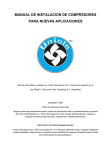
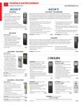
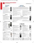
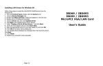
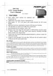
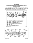
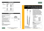
TM
UWX440/550
Compressor
Service Manual
440/550 Series Compressor Service Manual
Table of contents:
1.Specifications
UWX440/550 ………………………………………………….…………1
Magnetic clutch …………………………………………………………2
2. Component part list
I. Compressor part numbers ……………………………………………3
II. Exploded view …………………………………………………………4
3.Service
Service tools part numbers …………………………………………… 5
Bolt torque specifications ………………………………………………5
Service tools ………………………………………………………………6
Removal of magnetic clutch ……………………………………………7
Installation of magnetic clutch ………………………………………… 8
Removal of mechanical seal ……………………………………………9
Installation of mechanical seal …………………………………………9
Installation of mechanical seal continued ……………………………10
Disassembly of body ……………………………………………………10
Assembly of body ……………………………………………………… 11
Assembly of body continued ………………………………………… 12
System oil quantity ……………………………………………………13
Oil type and grade ………………………………………………………13
Storage guidelines ……………………………………………………13
®
Copyright ©2007 All rights reserved
No part of this document shall be reproduced in whole or in part without the permission of Unicla International Ltd. This
includes reproduction or copies in any form or by any means including photocopying, printing or electronic media.
IMPORTANT DISCLAIMER
This is a guideline document containing professional information using representative graphs, charts and tables.
Manufacturers’ specifications must be consulted for specific guidelines and performance data. Unicla published data, specific to
all models, is available in promotional literature and from Unicla International Ltd on request or through your Unicla supplier.
Unicla International Ltd expressly disclaims all and any liability and responsibility to any person or business as a result of any
actions taken on the basis of information in this publication.
1.
Specifications
Top view
Rear view
Side view
Compressor Model
UWX440
UWX550
Number of cylinders
14
14
Displacement
508 cc/rev
607 cc/rev
Refrigerant
HFC-134a
HFC-134a
Initial oil charge
1000 cc
1000 cc
Oil type
Unidap 7 (PAG oil) Unidap 7 (PAG oil)
Weight without clutch 24kg
24kg
Bottom view
Magnetic clutch
Diameter 178mm
Diameter 210mm
2.
Compressor part numbers
3.
No.
1.1
1.2
2
3
4
5
6
7
8
9
10
11
12
13
14
15
16
17
18
19
20
21
22
23
24
25
26
27
28
29
30
31
32
33
34
35
Part number
22010-000360
22010-000370
21405-000750
21510-000040
21505-000250
21501-000010
21510-000030
22601-000080
22601-000090
22602-000260
93204-00090
93204-000100
92503-000110
23101-000010
53101-000080
35801-000010
13201-000240
13201-000230
38101-000040
42203-000200
32308-000590
93203-000010
93203-000020
92404-000040
42203-000161
38305-000030
38101-000020
38101-000030
42102-000010
13201-000010
11950-11000
92501-000500
92501-000490
91913-100604
91913-10045
91013-10035
Description
440 working assembly
550 working assembly
Body
Front cap
Rear cap
Head cover
Front nose
Valve plate front assembly
Valve plate rear assembly
Valve plate suction
Gasket front
Gasket rear
Mechanical seal assembly
Gear pump
Thermal switch
Sight glass
Plug
Plug (M14)
Shut-off valve
Copper spigot
Flange
Gasket A
Gasket B
Snap ring
Nipple, Oil separator
Relief valve assembly
L charge valve
H charge valve
Oil pipe
Plug (M12)
Felt
O ring
O ring
Bolt (M10 x 60)
Bolt (M10 x 45)
Bolt (M10 x 35)
Qty
1
1
1
1
1
1
1
1
1
2
1
1
1
1
1
2
1
2
2
2
2
2
2
1
1
1
1
1
1
1
1
2
1
4
12
4
36
91913-08030
Bolt (M8 x 30)
10
37
91913-08020
Bolt (M8 x 20)
6
Exploded view
UWX440/550
33
31
UWX440/550
4.
Service tool part numbers
No.
1
2
3
4
5
6
7
8
9
10
11
12
13
14
15
16
17
18
19
20
Part number
03301-004230
03301-003140
03301-003180
03301-003190
03301-004950
03301-000490
03301-003230
03301-000350
03301-000370
03301-012370
03301-010010
03301-000380
03301-000440
03301-000450
03301-000400
03301-000410
03301-000390
03301-000430
03301-000420
03301-000650
Description
Working assembly bench
Stand
Remover/installer, mechanical seal
Installer, ring
Shaft rotating handle
Guide pin
Remover, mechanical seal plate
Installer, pulley
Clutch wrench
Pulley pad
Hub remover, clutch
Torque wrench
14mm socket
8mm hexagonal socket
Thickness gauge
Remover, pulley
Plastic hammer
Snap ring pliers (Shaft)
Snap ring pliers (Hole)
6mm hexagonal socket
Bolt torque specifications
Description
Housing cap bolts
High/low service valve
Blind plugs
Clutch coil bolts
Armature bolt
5.
Bolt diameter (mm)
M10
M12
M8
M6
M8
Tightening torque (N•m)
33.3 - 35.3
10.8 - 12.7
23.5 - 25.5
6.9 - 8.8
18.6 - 20.6
Service tools
- Genuine Unicla tools
1 03301-004230
5 03301004950
9 03301000370
15 03301000400
- Optional generic tools
2 03301-003140
6 03301000490
11 03301010010
10 03301012370
16 03301- 17 03301000390
000410
3 03301003180
7 03301- 003230
12 03301000380
8 03301- 000350
13 03301000440
18 03301000430
4 03301003190
14 03301000450
19 03301000420
20 03301000650
6.
Removal of magnetic clutch
Wrench
I. Removal of armature bolt
Tools required: • Stand • Clutch wrench
• Wrench • 14mm socket
Procedure: Place the compressor on the stand. Hold clutch by
inserting the claws of the clutch wrench into the holes on the
armature. Remove the centre bolt by using the wrench
Clutch
wrench
Hub
remover
II. Removal of armature
Tools required: • Hub remover
Procedure: Pull the armature upwards
III. Removal of snap ring
Tools required: • Snap ring pliers (shaft)
Procedure: Remove the snap ring with the snap ring pliers
Snap ring
pliers
IV. Removal of pulley assembly
Tools required: • Remover, pulley • Wrench • Pulley pad
Procedure: Remove the pulley assembly with the remover and pad
V. Removal of coil
Tools required: • Standard screwdriver
Procedure: Remove 3 M6 bolts with screwdriver
Pulley pad
in place
VI. Inspection of clutch components
1. Armature - Contact surface must be clean, smooth and
unmarked, with no abnormal scoring
2. Pulley - Contact surface must be clean, smooth and
unmarked, with no abnormal scoring
3. Coil - Wiring harness must be in good condition
(+) Driver
Pulley
Armature
7.
Coil
Installation of magnetic clutch
I. Installation of coil
Tools required: • Stand • Standard screwdriver
Procedure: Tighten 3 bolts (wire must be visible at 1 o’clock
position, when viewed from the front)
Tightening torque: 7.8 ±1 N•m
(+) Driver
Wire
Hammer
II. Installation of pulley
Tools required: • Pulley installer • Plastic hammer
Procedure: Place the pulley on the nose top and install it by
tapping on the installer until it stops. Do not tap if the pulley is
not located correctly
Pulley installer
III. Installation of clutch key and snap ring
Tools required: • Snap ring pliers (shaft)
Procedure: Install the snap ring into the groove (tapered side
up). Install the key in keyway
IV. Installation of shims and armature
Tools required: • Guide pin
Procedure: Install the guide pin into the centre threaded hole
of the shaft and select shims (T=0.1, 0.3 and 0.5mm) to ensure
the clutch clearance
Snap ring pliers
Snap ring
V. Installation of armature
Tools required: • Clutch wrench • Torque wrench
• 14mm Socket
Procedure: Place washers and spring washers on M8 bolt.
Hold clutch by inserting the claws of the clutch wrench into
the holes on the armature. Tighten the centre bolt by using the
wrench
Tightening torque: 19.6 ± 1 N•m
VI. Air gap
Tools required: • Thickness guage
Procedure: Ensure clutch clearance is correct all around
(0.3mm≤ gap ≤0.6mm)
Clutch
wrench
0.3≤ Gap ≤0.6
Thickness
gauge
8.
Removal of mechanical seal
Socket wrench
I. Removal of front nose
Tools required: • 6mm hexagonal socket
Procedure: Remove M8 bolt (6 locations) with socket wrench
Remove key. Tap edge of key with driver or punch
Do not damage shaft
II. Removal of snap ring
Tools required: • Snap ring pliers (hole)
Procedure: Remove the snap ring slowly with pliers as shown
III. Removal of plate ring
Tools required: • Remover, plate ring
Procedure: Hook and remove plate ring with remover as shown,
turn around lightly and pull it
Key
Snap ring
IV. Removal of seal
Tools required: • Remover, mechanical seal
Procedure: Push remover lightly. Turn right and hook, then
remove upward slowly
V. Removal of oring
Tools required: • Hook tool
Procedure: Remove oring with hook tool
Plate ring
remover
VI. Inspection of mechanical seal component
Caution - plate ring must be clean and unmarked
Seal remover
Installation of mechanical seal
I. Installation of seal
Tools required: • Installer, seal
Procedure: Install oring. Insert seal until stop point, then
turn right. Fix on shaft notch. Place the remover on the seal
correctly and press the seal with the remover until it stops
Caution - damage will occur if too much force is used.
Do not touch surface on seal ring
II.Installation of plate ring
Tools required: • Installer, ring
Procedure: Insert ring (moving surface side to be downward)
until in stop position
9.
Installation of mechanical seal - continued
III. Installation of snap ring
Tools required: • Snap ring pliers (hole) • Installer ring
Procedure: Insert the snap ring into nose section (tapered
part of the snap ring must be facing downwards). Push the snap
ring downward with the installer, and fit into groove
Seal remover
IV. Installation of felt seal
Tools required: • Installer ring
Procedure: Install the felt seal into the nose section
Push the felt seal until it touches the snap ring
Ring installer
Disassembly of body
Caution - o ring should not be reused.
I. Removal of oil
Procedure: Remove the drain plug and drain the oil
II. Removal of seal (Refer to page 9 for instructions)
III. Removal of bolts on rear cap
Tools required: • 8mm hexagonal socket • Stand
Procedure: Remove the M10 securing bolts (6pcs) from the
rear cap
Socket
wrench
IV. Removal of rear cap
Procedure: Remove the rear cap by gently inserting a screw
driver or lever into the recess. Lever all around, not just at one
position
Caution - do not damage cap or body.
10.
V. Removal of valves and
working assembly
Procedure: Remove rear gasket,
valve plate and suction valve.
Remove oil pipe first then remove
working assembly by pressing the
end of the shaft into the front of
the body as shown. Remove front
gasket, valve and suction valve
VI. Removal of front cap
Tools required: • 8mm hexagonal socket
Procedure: Remove the M10 bolts (6pcs) from the front cap.
Remove the front cap by gently inserting a screwdriver or lever
into the recess. Lever all around, not just at one position
Caution - do not damage cap or body.
Assembly of body
I. Installation of the oring for front and rear cap
Procedure: The o-ring must be free from marks and dust.
Thoroughly lubricate new o-ring properly and insert into
the groove. Ensure the o-ring is lying straight in the groove
without a twist
II. Installation of the front cap
Tools required: • Torque wrench • 8mm hexagonal socket
Procedure: Place the body with front section facing upward.
Place the front cap on the body (be careful not to twist the
oring). Tighten M10 bolts (6pcs) with torque wrench
Tightening torque: 34.3 ±1 N•m
III. Installation of the front valve plate and body
Tools required: • Working assembly bench
Procedure: Place the working assembly on locating pins.
Stack the suction plate, the valve plate and gasket on
locating pins in sequence as shown. Carefully lower the body
over the working assembly until it stops next to the working
bench guide
11.
Assembly of body - continued
IV. Installation of rear valve plate
Tools required: • Stand
Procedure: Insert vacuum pipe. Place the body in an
inverted position on the stand and stack the suction plate,
valve plate and gasket as shown, install the gear pump
V. Inspection, tightening and clearance of the rear cap
Tools required: • Torque wrench • 8mm hexagonal socket
• Thickness guage
Procedure: Place the rear cap on the body (be careful not
to twist the oring). Tension the M10 bolts (6pcs) diagonally,
alternately and carefully.
Check the rear cap clearance as specified: 0.4≤ Gap ≤1.2mm
Tightening torque: 34.3 ±1 N•m
VI. Installation of mechanical seal
(Refer to page 9)
VII. Installation of front nose and key
Tools required: • Torque wrench • 6mm hexagonal socket
Procedure: Install the key in keyway. Install front nose with
M8 bolts (6 pieces). Clutch lead wire groove is located at 1
o’clock position as shown on page 8.
Tightening torque 24.5 ±1 N.m
VIII. Test working assembly rotation
Tools required: • Shaft rotating handle
Procedure: Install the handle into the front section to check
the shaft rotates smoothly
Wire groove
IX. Filling compressor oil
Procedure: Fill the following amount of oil into the low
pressure port as shown. Ensure drain correctly plugged
Standard oil type: Unidap 7 (PAG) or Unidap 6 (POE)
Amount of oil = 1000 ± 20cc
X. Plug cap on oil port
Tools: • 8mm hexagonal socket
Procedure: Tighten high/low pressure port cap bolts
Tightening torque: 34.3 ±1 N•m
12.
System oil quantity
The correct amount of oil must be maintained in the compressor and system. Long hose runs
and dual evaporator systems must have additional oil added to the system. Severe oil starvation
problems may result from insufficient system oil being allowed. To determine oil quantity
required, Unicla recommends a calculation as a percentage of refrigerant charge as follows:
• 20% for UWX440/550 compressors in standard applications where the suction and discharge lines are less than 6 metres in length
• 30% for UWX440/550 compressors in applications where suction and discharge lines exceed 6m in length
Example:
Calculate oil charge as 20% of refrigerant charge, 5 kg charge = 5000 g x 20% = 1000 ml (cc) of
oil. If fitting a UP/UX200 compressor, then deduct the compressor initial oil charge to determine
amount of oil to be added. Therefore 1000 – 600 = 400cc oil to be added to system
Oil type and grade
Each Unicla UWX compressor is fitted with either PAG oil (Unidap 7) or POE oil (Unidap 6). When adding
oil to the system, Unicla oil must be used.
Warranty is void if these guidelines are not followed
Compressor
Model
Refrigerant
Oil Type
(Unicla)
Viscosity @ Viscosity @
40˚C
100˚C
UWX440/550
R134a
Unidap 7
48.01
UWX440/550
R134a
Unidap 6
65.5
Application
Low side
Saturation
Oil Separator
10.51
Airconditioning
> 0˚C
Optional
9.3
Airconditioning
>0˚C
Optional
The following labels will determine the type of oil in each UWX440/550 compressor:
POE type
PAG type
Storage guidelines
I. Evacuate compressor for 3 minutes and fill with nitrogen (N2) at 0.1 ~ 0.2 MPa
II. Place the compressor in a clean and dry area with low humidity and tag with details
III. Keep compressor away from direct sunlight
IV. Store the compressor horizontally on a flat, even surface
V. Do not store the compressor in temperatures above 30˚C
VI. Place the compressor in a well ventilated area to avoid corrosion damage
*The contents of this manual are subject to change without prior notice
13.
®
Unicla International Limited
Unit 1109, 11F Manhattan Centre,
8 Kwai Cheong Rd, Kwai Chung, N.T.,
Hong Kong
Phone (852) 2422 0180
Fax (852) 2422 0680
Email: [email protected]
Website: www.unicla.hk
Unicla Cat. No. M1204