1
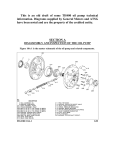
SECTION A
DISASSEMBLY, INSPECTION, AND OVERHAUL OF THE
CENTER SUPPORT
Figure 13A-1 is the master schematic of the center support assembly with the cast
aluminum intermediate clutch piston. Figure 13A-2 is the master schematic of the
center support assembly with the stamped steel intermediate clutch piston.
FIGURE 13A-1
FIGURE 13A-2
GM
AMC/JEEP
Press down on the intermediate clutch spring retainer (647) and remove the snap
ring (646) that fastens it to the center support. See Figure 13A-3. Lift off the
retainer. See Figure 13A-4.
FIGURE 13A-3
FIGURE 13A-4
GM
Remove the three intermediate clutch release springs (648) from the cast
aluminum intermediate clutch piston (650). See Figure 13A-5. Note that all 1964 and
1965 models, as well as all 1966 to 1972 Cadillacs were fitted with 12 intermediate
clutch release springs. Inspect the release springs for cracks, fatigue, and distortion.
Shiny wear visible on the spring outside diameter is considered normal. With
models that use the stamped steel intermediate clutch piston, remove the three
intermediate clutch release springs followed by the plastic intermediate clutch
spring guide (649). See Figure 13A-6.
FIGURE 13A-5
GM FIGURE 13A-6
GM
Remove the intermediate clutch piston (650) from the center support (654).
Removal of the cast aluminum piston is shown in Figure 13A-7. Removal of the
stamped steel piston is shown in Figure 13A-8.
FIGURE 13A-7
GM
FIGURE 13A-8
GM
As noted, the intermediate clutch piston may be either cast aluminum or stamped
steel. The cast aluminum piston is shown in Figure 13A-9. The stamped steel piston
is shown in Figure 13A-10.
FIGURE 13A-9
FIGURE 13A-10
Remove the outer (652) and inner (651) lip seals from the intermediate clutch
piston. See Figures 13A-11 and 13A-12. Examine the seals and become familiar with
how they fit the piston and seal in the support. Do not discard the seals. You will use
them to identify the replacement seals later on during assembly. Inspect the piston
for cracks. Inspect the piston seal grooves for nicks or damage.
FIGURE 13A-11
GM FIGURE 13A-12
GM
Remove and discard the four oil seal rings (653) from their ring grooves in the
center support. See Figure 13A-13. 1964 to 1974 models were assembled with cast
iron hook type oil seal rings. 1975 and up models received scarf cut Teflon type oil
seal rings. See Figure 13A-14.
FIGURE 13A-13
GM
FIGURE 13A-14
GM
Inspect the seal ring grooves for signs of wear or damage. See Figure 13A-15. If
any of the seal rings are stuck or sticking in their grooves, check the seal ring
grooves for signs of damage resulting from contact with the direct clutch housing.
When the direct clutch housing operates with excessive radial runout, the seal ring
bore on the inside diameter of the housing comes in contact with the outside
diameter of the seal ring grooves. This results in the peening over or closing of the
seal ring groove openings. Inspect and replace the center support if necessary.
When using cast iron, solid Teflon, or Peak oil seal rings, test fit the rings in their
respective grooves. Insert the outside diameter of the ring into the ring groove and
rotate it around the full diameter of the groove. See Figure 13A-16. The ring should
rotate smoothly around the groove. If the ring fails to rotate smoothly, inspect the
groove for nicks or burrs. Remove any imperfections with a small file and recheck.
Seal ring groove width should measure @ approximately .095”. Ring groove depth
should measure @ approximately .090”.
FIGURE 13A-15
FIGURE 13A-16
Verify the presence of the bleed orifice cup plug installed in the intermediate
clutch piston cavity. See Figure 13A-17. Verify the bleed orifice in the cup plug is
free of obstruction and/or debris. Note that all 1964 and 1965 models, as well as all
1966 to 1972 Cadillacs were fitted with center supports void of the orifice cup plug.
FIGURE 13A-17
GM
The reaction carrier bushing journal is an integral part of the center support. See
Figure 13A-18. Inspect the bushing journal for any signs of abnormal wear. Use
your fingernail to check for scoring or grooving of the journal. Minor scoring can
sometimes be removed with a fine grit emery cloth. Lubrication for the reaction
carrier bushing is supplied thru a hole in the bushing journal. Verify the oil hole in
the bushing journal is free of obstruction and/or debris. See Figure 13A-19. Prepare
the journal by gently polishing it with a fine scotch pad.
FIGURE 13A-18
FIGURE 13A-19
Measure the bushing journal with a micrometer. See Figure 13A-20. The
specification for the bushing journal diameter is 2.187” to 2.1875”. The low roller
clutch inner race is an integral part of the center support. See Figure 13A-21.
Inspect the race for any signs of abnormal wear or damage. Use you fingernail to
check for scoring or grooving of the race.
FIGURE 13A-20
FIGURE 13A-21
The inner race is pinned and bolted to the center support. See Figure 13A-22. DO
NOT remove the bolts. Inspect the threads that receive the center support to case
bolt for signs of damage or stripping. See Figure 13A-23.
FIGURE 13A-22
FIGURE 13A-23
Inspect the center support bushing for signs of wear, scoring, grooving, pitting or
flaking. Check the center support bushing to sun gear shaft clearance. Install the
sun gear shaft (664) into the center support. Install the largest feeler gage that just
fits in between the bushing and the shaft to obtain the clearance. See Figure 13A-24.
The specification for the clearance is .0015” to .005”. If there is excessive clearance,
the bushing should be replaced. The replacement center support bushing is shown
in Figure 13A-25. Before removing the bushing, note the orientation between the
center support bushing oil slot and the center support oil hole. See Figure 13A-26.
When installed, the bushing oil slot and the center support oil hole must be in
alignment. If not, lube oil to the intermediate sprag and intermediate clutch pack
will be reduced or completely cut off resulting in transmission failure. Using a press
and bushing driver, remove the center support bushing from the center support. See
Figure 13A-27. Always remove the bushing starting at the rear end of the support,
“pushing” the bushing out the front end of the support.
FIGURE 13A-24
FIGURE 13A-26
FIGURE 13A-25
AMC/JEEP FIGURE 13A-27
GM
Note that this bushing does not like to be installed with a hammer and bushing
driver. Align the bushing oil slot with the center support oil hole, and using an arbor
press install the bushing into the support. See Figure 13A-28. Install the bushing
flush with the top of its bore. Once again verify that the bushing oil slot and the
center support oil hole are in alignment. Flush the center support out with clean
solvent and blow dry with compressed air to remove any material generated during
bushing installation. To verify the bushing has been installed properly, lube the
bushing and install the sun gear shaft into the support and verify smooth rotation.
See Figure 13A-29.
FIGURE 13A-28
FIGURE 13A-29
Air check the center support oil passages to verify they are not interconnected.
See Figure 13A-30.
FIGURE 13A-30
GM
Use Figure 13A-31 as a guide to reassemble the center support and related
components.
FIGURE 13A-31
GM
Install the inner (651) and outer (652) intermediate clutch piston lip seals onto
the intermediate clutch piston (650). See Figures 13A-32 and 13A-33.The lip of the
seals will point towards the rear of the piston.
FIGURE 13A-32
GM FIGURE 13A-33
GM
Before attempting installation of the piston, take note of how the protruding
spring pockets at the rear of the intermediate clutch piston fit into the spring pocket
cavities in the front face of the center support. See Figures 13A-34 and 13A-35.
FIGURE 13A-34
FIGURE 13A-35
Lubricate the lip seals and install the intermediate clutch piston down over the oil
seal ring boss of the center support. Install a .008” to .010” feeler gage between the
inner lip seal and the inner lip seal boss to guide the piston into the support.
Without cocking the piston, apply a slight downward pressure with one hand, while
rotating the feeler gage around the inner diameter of the piston. See Figure 13A-36.
As the piston begins to enter its cavity in the support, it will drop down about .100”
over the inner lip seal boss. Next, work your way around the outside diameter of the
outer lip seal with the smooth, rounded 90 degree corner of your pick tool to gently
guide the seal into its cavity. Do this while applying a slight downward pressure
until the piston is fully seated. See Figure 13A-37. When fully seated, the rear ledge
of the piston face will bank against the front face of the center support.
FIGURE 13A-36
FIGURE 13A-37
Figures 13A-38 and 13A-39 show two versions of the service manual method and
tooling for installing the piston. This tool is not necessary for the seasoned
professional, but may be helpful to the production or novice builder.
FIGURE 13A-38
AMC/JEEP FIGURE 13A-39
GM
Install the three intermediate clutch release springs (648) into the cast aluminum
intermediate clutch piston (650). Be sure to install the springs evenly spaced. See
Figure 13A-40. With all 1964 and 1965 models, and all 1966 to 1972 Cadillacs install
12 intermediate clutch release springs. With models that use the stamped steel
intermediate clutch piston, install the plastic intermediate clutch spring guide (649)
into its cavity in the piston, followed by the three intermediate clutch release
springs. See Figures 13A-41 and 13A-42. Install the intermediate clutch spring
retainer (647)) on top of the springs. See Figure 13A-43.
FIGURE 13A-40
GM FIGURE 13A-41
AMC/JEEP
FIGURE 13A- 42
AMC/JEEP FIGURE 13A-43
AMC/JEEP
Compress the retainer and install the snap ring (646). See Figure 13A-44. Figure
13A-45 shows the service manual method and tooling for the job. When working
with pistons that use three release springs, the retainer may be compressed by hand.
Verify the clutch release springs are not leaning. If necessary, straighten them with
a small screwdriver. Air check the clutch piston for proper operation by applying 20
to 25 PSI of compressed air to the intermediate clutch passage in the center support.
See Figure 13A-46. Note that using excessive pressure during the air check can blow
the piston and seals out of the bore and can result in parts damage or personal
injury. Applying air pressure should result in the piston pumping up against release
spring pressure. Releasing air pressure should result in the piston retracting against
release spring pressure. Most center supports will have the bleed orifice cup plug in
the rear. See Figure 13A-47. A small amount of air is expected to escape out of the
bleed orifice, but there should be no leakage from the lip seals. If the piston fails to
pump up or release, disassemble the components and check for the problem before
continuing. A final check with full pressure will be performed during the final
assembly of the transmission. Install the thrust washer (656) into its recess in the
rear of the center support. Retain the washer with assembly lube. See Figure 13A47.
FIGURE 13A-44
FIGURE 13A-45
FIGURE 13A-46
GM FIGURE 13A-47
GM
GM
Install four oil seal rings (653) into the ring grooves in the center support. See
Figure. Note that with applications which dual feed the direct clutch housing, the
omission of the second oil seal ring from the top of the seal ring boss is required. If
the dual feed methods in this publication are being implemented, the omission of the
seal ring is required. Note that the use of cast iron seal rings is not recommended in
any TH400 with fixed line pressure or line pressure values greater than stock. Rapid
seal ring, ring groove and direct clutch housing bore wear will most certainly result.
Teflon or Peak oil seal rings are preferred. Proper orientation of cast iron hook type
seal rings is shown in Figure.
FIGURE
GM FIGURE
Proper orientation of Teflon scarf cut seal rings is shown in Figure. Properly
installed Peak seal rings are shown in Figure.
FIGURE
GM FIGURE
Solid Teflon sealing rings were fitted to the center support of early model 4L80E
transmissions. See Figure. These rings will retro-fit the TH400 center support but
require the use of specialized installation tools or some ingenuity on the part of the
installer. A sleeve is fit over the sealing ring boss, and its height adjusted so that its
leading edge is just above the seal ring groove the ring will be installed in. The
sealing ring is then placed over the conical end of the sleeve, and a second tool is
used to push the ring down over the sleeve, stretching the inside diameter just
enough so that it can enter the ring groove. See Figure.
FIGURE
FIGURE
A sizing tool is then fit down over the rings and rotated, sizing the rings to the
proper dimension. See Figure. A completed solid seal ring retro-fit is shown in
Figure. Note the omission of the second oil seal ring, indicating the direct clutch
housing is being dual fed.
FIGURE
FIGURE
SECTION B
IDENTIFICATION AND INTERCHANGE OF THE CENTER
SUPPORT AND RELATED COMPONENTS
Identify the type of center support in use. There are first design and second
design supports. There are early and late versions of the first design. Most early and
late first design supports share the same casting number, 8623138. The early first
design support was used in all 1964 to mid-year 1969 models, and can be identified
by measuring the width of the center support to case lugs. See Figure 13B-1. The lug
width will measure in @ approximately .370”, and it does not install into the
transmission case with the center support to case anti fretting ring (657). See Figure
13B-2. The late first design support was used in all late 1969 to early 1990 models,
and can be identified by measuring the width of the center support to case lugs. The
lug width will measure in @ approximately 330”, and the support installs into the
transmission case in conjunction with the anti fretting ring. To accommodate the
ring, the lug width was reduced the same amount as the ring width. The purpose of
the ring is to insulate the support ledge in the transmission case from center support
rearward thrust and radial movement that results in case damage. Without the ring,
the support lugs tend to eat or fret the transmission case at the lug to ledge
interface. Because early models do not have the ring, increased case wear results in
this area. It is always recommended to update to the anti fretting ring/late first
design center support combination on models not originally equipt with these
components. The early first design support may be used with the anti fretting ring
by machining .040” from the rear face of the case lugs. If you try to install the anti
fretting ring with the early first design center support, you will not be able to
properly install the center support bolt (79) or the beveled snap ring (645).
FIGURE 13B-1
FIGURE 13B-2
GM
Note that all 1964 and 1965 models, as well as all 1966 to 1972 Cadillacs were
fitted with a center support assembly void of a bleed orifice cup plug in the
intermediate clutch piston cavity. See Figure. Note that these models also used
twelve intermediate clutch release springs (648) instead of the usual three installed
in all other models. Unlike later models, these supports are void of center support to
case lugs in the casting at the area shown in Figure. Although the lugs are present
on later model supports, the case has always been void of “receiver grooves” in that
area. This alludes to the fact that it was easier to manufacture the support with all
of the lugs rather than to “time” each support during the machining process.
FIGURE
FIGURE
Because the center support is filled from the bottom up, air tends to get trapped
in the piston cavity when the circuit is exhausted or not charged with intermediate
clutch oil. Without a bleed orifice, this trapped air acts as a variable accumulator in
the circuit. This prevents maximum apply pressure from being reached during 1-2
upshifts, reducing intermediate clutch capacity, resulting in intermediate clutch
slippage. For all 1966 models, with the exception of Cadillac, who followed suit for
their 1973 models, a .020” bleed orifice cup plug was installed in the intermediate
clutch piston cavity. See Figure. The purpose of the bleed orifice cup plug is to
purge trapped air from the intermediate clutch piston cavity during intermediate
clutch application. Due to the tendency of the support void of the orifice cup plug to
reduce clutch capacity and shift quality, its usage in any heavy duty or performance
application is not recommended.
INFORMATION IN NEXT SECTION HAS BEEN EXTENSIVELY UPDATED.
THE EXACT REASON FOR THE BOLT CHANGE AND 2 LUGS HAS BEEN
UNCOVERED.
All TH400 transmissions produced after March 1, 1990 received a revised center
support casting. This is known as the second design center support. The casting
number for the second design center support is 8678032. This is the same support
used in all production 1991 to 1995 GM 4L80E transmissions. This support uses the
anti fretting ring and the width of the lugs measures approximately .330”. The
8678032 casting has slight differences in non critical dimensions when compared to
the 8623138 casting, however; they do not affect fit or function. The second design
support also received a different center support to case bolt. This bolt is longer than
the previous design and must be used with second design supports only. See Figure
13B-3. When used with the anti fretting ring and proper center support to case bolt,
the second design center support is fully interchangeable with both the early and
late first design center supports.
FIGURE 13B-3
GM
Beginning on December 21, 1993 some TH400 GM Goodwrench Replacement
Transmissions that used the second design support were built with a new case to
center support service bolt. The bolt is coated with zinc chromate and is yellow in
color. According to GM, the reaming of the threaded hole and the installation of the
new bolt allowed the support to be reconditioned in the field one time before
replacement. See Figure 13B-4. Apparently the engineers believed that the support
was a wear item and was to be replaced during overhaul. The service bolt and
instruction sheet is available under GM Part Number 24202218.
FIGURE 13B-4
GM
There is a unique difference found when comparing the first and second design
center supports. The first design center support uses 17 full width center support to
case lugs. See Figure 13B-5. The second design center support only uses two full
width center support to case lugs. See Figure 13B-6. No technical information
regarding the reasoning for the change has ever been made available. It is evident
that the reduced lug count can allow increased radial movement between the center
support to case interface under extreme loading conditions in Lo range.
FIGURE 13B-5
FIGURE 13B-6
Intermediate Clutch Piston
From 1964 to 1973, all TH400 transmissions were built with the cast aluminum
intermediate clutch piston. See Figure 13B-7. In 1974, the stamped steel
intermediate clutch piston was introduced and used on some models, while the
aluminum piston was used on others. See Figure 13B-8. Use of the stamped steel
piston continued until the end of the 1984 model year, at which time its use was
discontinued. Note that unlike the aluminum piston, the steel piston is void of
release spring pockets. To provide a means for locating the springs, the plastic
intermediate clutch spring guide is used with the steel piston. Both intermediate
clutch piston combinations are fully interchangeable. Steel piston usage in
performance builds is not encouraged. With increased line pressure, it suffers from
deflection and a narrow work surface, reducing clutch pack performance. The
piston work surface is the area of the front face of the piston that contacts and
pushes on the first steel in the clutch pack. See Figure 13B-9. Note the narrow work
surface of the steel piston compared to the wide work surface of the aluminum type.
FIGURE 13B-7
FIGURE 13B-8
FIGURE 13B-9
Installing 4L80E Intermediate Clutch Piston and or Wave Plate into the
TH400
The terms “overall work surface height” (“A”), “work surface” (“B”), and
“counterbore diameter” (“C”) describe piston features pertinent to identification
and interchange. See Figure 13B-10.
FIGURE 13B-10
There are two types of production cast aluminum intermediate clutch pistons
for the 4L80E. 1991-1995 models received part number 8661657 and are known as
the early pistons. 1996 and up models received part number 24202553 and are
known as the late pistons.
EARLY PISTON # 8661657
LATE PISTON # 24202553
Functional dimensions between the early 4L80E intermediate clutch piston and
the TH400 stamped steel or cast aluminum piston are similar with one exception. As
cast, the overall work surface height of the 4L80E piston measures .140”, compared
to .155” with the TH400 piston. This will result in a .015” increase in intermediate
clutch pack end clearance when retrofitting. This is no major cause of concern, and
if necessary, clutch pack end clearance can be adjusted during final transmission
assembly. All early 4L80E intermediate clutch pistons will retro-fit all TH400
transmissions.
Late model 4L80E transmissions incorporate the use of a waved plate installed
between the intermediate clutch piston and the first steel plate in the clutch pack as
a cushioning device. See Figure 13B-11.
FIGURE 13B-11
GM
Clutch piston dimension revisions accommodate the waved plate. Locating tabs
on the inside diameter of the wave plate permit the locating of the waved plate to the
counterbore of the piston. See Figure 13B-12. The counterbore diameter was
enlarged from 5.125” (common between all TH400 and early 4L80E intermediate
clutch pistons), to 5.225”, providing the necessary clearance for the waved plates
locating tabs. See Figure 13B-13.
FIGURE
FIGURE
The piston overall work surface height was reduced from .140” to .090”,
restoring clutch pack end clearance lost with the addition of the waved plate. This is
where a potential problem can occur. Whenever installing a late 4L80E
intermediate clutch piston into a TH400, the matching waved plate (684) must also
be used. If not, the first steel plate in the clutch pack will not rest on the piston as
intended. Instead, it will sit on top of the beveled center support to the case snap
ring (645). See cut away view in Figure 13B-14. This will result in excessive
intermediate clutch piston travel and possible functional problems may result.
When used as a set, the late 4L80E intermediate clutch piston and matching waved
plate will retro-fit all TH400 transmissions.
When installing the 4L80E waved plate into a TH400 with a TH400 or early
4L80E intermediate clutch piston, the piston counterbore must be machined to the
revised counterbore dimension.
FIGURE 13B-14
SECTION C
COMPONENT UPGRADES AND MODIFICATIONS
Creating a Thrust Surface in the Front Face of the Center Support
Normal operating conditions result in the forward clutch housing assembly
thrusting rearward into the mainshaft (681). In high load applications this rearward
thrust can push the mainshaft with enough force to result in damage to the # 22
thrust bearing assembly (686, 687, 688) and output shaft to case thrust and selective
washers (695,696). By creating a thrust surface in the front face of the center
support, this rearward thrust can be cancelled out at the center support without
making it to the mainshaft. The origin of this rearward thrust begins in the torque
converter. Pressurized converter charge oil in the torque converter creates a force
that acts on the front face of the input shaft (601). The amount of this force
(measured in pounds) is calculated by multiplying converter charge pressure by the
surface area of the front face of the input shaft. Typically, “corrected”* converter
charge pressure in a high load application will be @ 60 PSI. The surface area of a
production input shaft is .785”. This combination results in 47.1 pounds of rearward
force acting on the front face of the input shaft and forward clutch housing
assembly. This force is then transmitted to the mainshaft at the interface between
the forward clutch hub (616), and the mainshaft. This occurs because the front end
of the mainshaft acts as a stop for the front end of the forward clutch hub. See
Figure 13C-4.
FIGURE 13C-4
* Please note that the term “corrected” used in the above paragraph is referring to a
converter charge circuit that has been modified to reduce dangerously high
converter charge pressures using the techniques in this manual. If left uncorrected,
converter charge pressure and rearward thrust values can be as much as double
that of the given example.
From the mainshaft, the force is transmitted to the rear internal gear (685) and #
22 thrust bearing assembly (686,687,688), then to the output shaft (691) and on to
the output shaft to case thrust and selective washers (695,696), where it is finally
grounded out at the transmission case. See Figure 13C-5. In heavy duty and high
load applications this can result in complete failure of the #22 thrust bearing
assembly.
FIGURE 13C-5
GM
The solution is to remove rearward thrust from the forward clutch housing
assembly to the mainshaft. This requires the creation of a thrust surface for the
forward clutch housing assembly independent of the mainshaft. This is performed
in two steps.
1. A thrust bearing assembly is installed between the front face of the forward
clutch hub (616) and the front thrust surface of the direct clutch housing
(633). This modification is shown in Section 11-B. This will divert rearward
thrust being applied to the mainshaft to the direct clutch housing. This force
is now transmitted to the sun gear shaft (664) at the interface between the
direct clutch housing and sun gear shaft. This occurs because the front end of
the sun gear shaft acts as a stop for the rear end of the direct clutch housing.
See Figure 13C-6. The force is then transferred from the sun gear shaft to the
sun gear (665), on to the # 21 thrust bearing assembly (682,683,684), followed
by the rear internal gear (685), and returning back to the #22 thrust bearing
assembly (686,687,688). See Figure 13C-7. At this point we have done nothing
more than reroute the rearward thrust we are trying to eliminate, back to the
#22 thrust bearing assembly whose durability we are attempting to improve.
However, because we have diverted rearward thrust into the direct clutch
housing, the housing can now be grounded to the center support, diverting
all rearward thrust into the support. Grounding the rear of the direct clutch
housing to the center support removes all rearward thrust at the interface
between the housing and the front of the sun gear shaft.
FIGURE 13C-6
FIGURE 13C-7
GM
2. A bearing pocket is machined at the bottom of the snap ring boss recess and
fitted with a thrust bearing, permitting the grounding of the direct clutch
housing to the center support. See Figure 13C-8. The pocket is machined to a
depth of .375” measured from the front face of the boss and to an inside
diameter of $$$ and an outside diameter of 2.875”.
FIGURE 13C-8
Selective shims installed between the thrust bearing and the bearing pocket
“push” the direct clutch housing off the sun gear shaft stop permitting it to thrust
against the center support.
Clearance adjustment is covered on page $$$. The thrust bearing and shim kit is
available under CK Performance part # 400CC/TBAWSP, and a machined center
support with thrust bearing and shim kit under CK Performance part #
400CC/RCSA.
FIGURE 13C-9
FIGURE 13C-10