1
BULLETIN A-30-647
Series 647 Wet/Wet Differential Pressure Transmitter
Specifications - Installation and Operating Instructions
GENERAL
PHYSICAL DATA
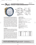
The Series 647 Wet/Wet Differential Pressure Transmitter
is designed for use with compatible liquids or gases and
can accurately measure differential pressure down to 1″
H2O. The transmitter contains a fast response piezoresistive sensor and a unique isolation system ideal for
HVAC systems, filter monitoring, variable speed drive
control, air/liquid flow monitoring, and process control.
Service: Compatible gases or liquids on both pressure and
reference sides.
Accuracy: ±1.0% FS.
Output: 4 to 20 mA, 2-wire.
Supply Voltage: 18 to 30 VDC.
Loop Resistance: 400Ω @ 18 VDC, 600Ω @ 24 VDC, 1000Ω
@ 30 VDC.
Zero and Span: Adjustable, ±10%.
Max Line Pressure: 60 psig.
Max Overload Pressure: Ranges 1″ w.c. to 5 psi: 20 psi, 15
psi range: 45 psi, 30 psi range: 60 psi.
Compensated Temperature Range: 32 to 122°F (0 to 50°C).
Storage Temperature: -40 to 212°F (-40 to 100°C).
Thermal Effects: Zero: ±0.05% FS/°F, Span: ±0.05% rdg/°F.
Stability: ±1.5% FS output/year.
Wetted Parts: Brass, vinyl, glass-filled polyester, silicon,
Buna-N, and fluorosilicon.
Housing: Gasketed steel epoxy painted, NEMA 4.
Process Connection: 1/8″ NPT(F).
Electrical Connection: Screw terminals, reverse polarity protected.
Weight: 14 oz (397 g).
The Series 647 Wet/Wet Differential Pressure Transmitter
features excellent repeatability, low hysteresis, and
accurate operation over a broad temperature range.
Units have an adjustable zero and span and feature
reverse polarity protection.
MECHANICAL INSTALLATION
NOTE: The Series 647 Wet/Wet Differential Pressure
Transmitter can be mounted in any position, however, be
alert to moisture passing through a non-waterproof electrical connector.
The unit can measure gauge, vacuum, or differential
pressure. Follow the directions below for the appropriate
port connections.
Gauge (Positive) pressure sensing: Connect media pressure to port labeled “HIGH”, with port labeled “LOW”
vented to atmosphere.
Vacuum (Negative) pressure sensing: Connect media
pressure to port labeled “LOW”, with port labeled
“HIGH” vented to atmosphere.
Differential pressure sensing: Connect the higher of the
two media pressures to port labeled “HIGH”, and the
lower of the two pressures to port labeled “LOW”.
DWYER INSTRUMENTS, INC.
P.O. BOX 373 • MICHIGAN CITY, INDIANA 46361 U.S.A.
MODELS
Model Number
647-0
647-1
647-2
647-3
647-4
Range
0 to 1″ w.c.
0 to 3″ w.c.
0 to 25″ w.c.
0 to 5″ w.c.
0 to 10″ w.c.
Model Number
647-5
647-6
647-7
647-8
Range
0 to 1 psid
0 to 5 psid
0 to 15 psid
0 to 30 psid
The Series 647 Wet/Wet Differential Pressure
Transmitters have 1/8 NPT female port connections.
ALWAYS USE A SECOND WRENCH TO HOLD THE
PORT HEX NUT, THEREBY ELIMINATING THE POSSIBILITY OF ROTATING THE BRASS PORT FITTING. Use
thread sealant or teflon tape to insure proper sealing.
Phone 219/879-8000
Fax 219/872-9057
Lit-by-Fax: 888/891-4963
www.dwyer-inst.com
e-mail: [email protected]
ELECTRICAL CONNECTIONS
Make all wiring connections with the power off. All circuits must be wired to the National Electrical Code,
Class 1, and in conformance with all applicable codes
and requirements with approved wiring practices. See
Figure 1 below for appropriate wiring connections.
4-20 mA, 2-wire, Field Conversion
to 1-5 VDC Signal
1
+ 24 VDC In
1
2
4-20 mA Signal Out
2
1-5 VDC
WARNING
Fluid hammer and surges can destroy any pressure
transducer and must always be avoided. A pressure
snubber should be installed to eliminate the damaging
hammer effects.
3
No Connection
Common
ZERO
Fluid hammer occurs when a liquid flow is suddenly
stopped, as with quick closing solenoid valves. Surges
occur when flow is suddenly begun, as when a pump is
turned on at full power or a valve is opened quickly.
SPAN
1
H
Do not adjust the bridge balance and temperature compensation controls.
+ 24 VDC In
250 Ohms
3
“S” - Span Control is adjusted to change the full
scale range of the transmitter.
Due to resistor values required to compensate for the
null off-set of the sensing module, evidence of Zero and
Span interaction may be experienced in readjusting.
Wiring Connections
24 VDC Power
4-20mA, 2-wire Loop Signal
“Z” - Zero Control is adjusted for 4 mA output
signal at 0 psi or minimum pressure.
2
3
L
MAINTENANCE
Figure 1
OPERATION
After applying power, allow approximately 20 to 30 minutes for stabilization of signal.
When operating at low differential pressures of less than
5″ w.c. or in applications where the pressure is fluctuating rapidly—it is advisable to insert “snubbers” for air
flow restrictors in the input lines. This serves to “steady”
the output signal and keeps the signal from bouncing
erratically.
After final installation of the Series 647 Wet/Wet
Differential Pressure Transmitter, no routine maintenance
is required. Periodic checks of connections is recommended. Please contact Dwyer Instruments, Inc. before
returning unit for repair to review information relative to
your application. When returning a product to the factory, carefully package and ship freight prepaid. Be sure to
include a complete description of the application and
problem and identify any hazardous material used with
the product.
Adjustments:
The Series 647 transmitters are adjusted for the specified range at the factory and should not require further
adjustments. If necessary or desireable, the zero and
span may be adjusted, however, the requested full scale
range as shipped is established with fixed resistors minimizing the range of adjustment. The average full scale
adjustment is ±10% of the range shipped.
©Copyright 1997 Dwyer Instruments, Inc.
Printed in U.S.A. 11/97
DWYER INSTRUMENTS, INC.
P.O. Box 373, Michigan City, Indiana 46360, U.S.A.
Phone: 219/879-8000
Fax: 219/872-9057