1
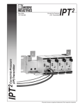
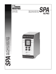
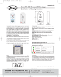
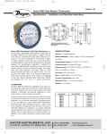
E-43-W(616)
8/16/06
8:53 AM
Page 1
Bulletin E-43-W
Series 616W Differential Pressure Transmitter
Specifications - Installation and Operating Instructions
Ø3/16 [4.76]
MOUNTING HOLES
TYP 4 PLACES
1-1/4
[31.75]
3-1/8
[79.38]
4-1/2
[114.30]
3-3/4
[95.25]
1-5/16
[33.32] TYP
5-1/8
7/16 OR 5/8
[130.18]
[11.13 OR 15.88]
TYP
1/8 AND 3/16
[3.18 AND 4.76]
1-3/16
I.D. TUBING
3/4
[30.18]
2-1/8 [19.05] TYP
[53.98]
4-17/32
[115.09]
3-1/8
[79.38]
Fig. A
The Dwyer Series 616W Differential Pressure Transmitter senses the pressure of air and non-combustible, compatible gases and
sends a standard 4-20 mA output signal.
All models, including those featuring LCD digital read-out, are factory calibrated to specific ranges, as listed in the chart on the next
page.
Positive, negative and differential pressures can be measured
within a full span accuracy of ±0.25%. This weatherproof unit is
enclosed in a polycarbonate case, rated (IP66/NEMA 4X).
The Span and Zero controls are for use when checking calibration.
They are not intended for re-ranging to a significantly different
span.
DWYER INSTRUMENTS, INC.
P.O. BOX 373 • MICHIGAN CITY, INDIANA 46361, U.S.A.
SPECIFICATIONS
Service: Air and non-combustible, compatible gases.
Wetted Materials: Consult factory.
Accuracy: ±0.25% F.S., display accuracy ±0.5%.
Stability: +1% F.S./yr.
Temperature Limits: 0 to 140°F (-17.8 to 60°C).
Compensated Temperature Limits: 20 to 120°F (-6.67 to
48.9°C).
Pressure Limits: See chart.
Thermal Effect: ±0.02% F.S./°F (0.0012% F.S./°C).
Power Requirements: 10-35 VDC (2-wire).
Output Signal: 4 to 20 mA.
Zero and Span Adjustments: Potentiometers for zero and
span.
Loop Resistance: DC; 0-1250 ohms maximum.
Current Consumption: DC; 38 mA maximum.
Electrical Connections: Screw-type terminal block.
Process Connections: Barbed, dual size to fit 1/8˝ and 3/16˝
(3.12 and 4.76 mm) I.D. rubber or vinyl tubing.
Enclosure Rating: NEMA 4X (IP66).
Mounting Orientation: Vertical, consult factory for other position
orientations.
Weight: Without LCD 8.8 oz (249 g); with LCD 9.6 oz (272 g).
Agency Approvals: CE.
Phone: 219/879-8000
Fax: 219/872-9057
www.dwyer-inst.com
e-mail: [email protected]
E-43-W(616)
8/16/06
8:53 AM
Page 2
SERIES 616W TRANSMITTER MODELS & RANGES
MODEL
NUMBER
PRESSURE
RANGE
MAXIMUM DIGITAL
PRESSURE DISPLAY
616W-0
616W-1
616W-2
616W-3
616W-4
616W-5
616W-6
616W-7
616W-8
616W-9
616W-10
616W-11
616W-12
616W-3B
616W-6B
616W-10B
616W-20B
616W-00-LCD
616W-0-LCD
616W-1-LCD
616W-2-LCD
0-2 in.w.c.
0-3 in.w.c.
0-6 in.w.c.
0-10 in.w.c.
0-20 in.w.c.
0-40 in.w.c.
0-100 in.w.c.
0-200 in.w.c.
0-10 psid
0-20 psid
0-30 psid
0-50 psid
0-100 psid
1.5-0-1.5 in.w.c.
3-0-3 in.w.c.
5-0-5 in.w.c.
10-0-10 in.w.c.
0-1 in.w.c.
0-2 in.w.c.
0-3 in.w.c.
0-6 in.w.c.
5 psig
5 psig
5 psig
5 psig
11 psig
11 psig
29 psig
29 psig
58 psig
58 psig
58 psig
150 psig
150 psig
5 psig
5 psig
5 psig
11 psi
5 psig
5 psig
5 psig
5 psig
0-1.00
0-2.00
0-3.00
0-6.00
MODEL
NUMBER
616W-3-LCD
616W-4-LCD
616W-5-LCD
616W-6-LCD
616W-7-LCD
616W-8-LCD
616W-9-LCD
616W-10-LCD
616W-11-LCD
616W-12-LCD
616W-3B-LCD
616W-6B-LCD
616W-10B-LCD
616W-20B-LCD
616W-OM-LCD
616W-1M-LCD
616W-2M-LCD
616W-3M-LCD
616W-4M-LCD
616W-5M-LCD
PRESSURE
RANGE
MAXIMUM DIGITAL
PRESSURE DISPLAY
0-10 in.w.c.
0-20 in.w.c.
0-40 in.w.c.
0-100 in.w.c.
0-200 in.w.c.
0-10 psid
0-20 psid
0-30 psid
0-50 psid
0-100 psid
1.5-0-1.5 in.w.c.
3-0-3 in.w.c.
5-0-5 in.w.c.
10-0-10 in.w.c.
0-500 Pa
0-750 Pa
0-1.5 kPa
0-2.5 kPa
0-5 kPa
0-25 kPa
5 psig
11 psig
11 psig
29 psig
29 psig
58 psig
58 psig
58 psig
150 psig
150 psig
10 in.w.c.
5 psig
5 psig
11 psig
34.5 kPa
34.5 kPa
34.5 kPa
34.5 kPa
75.8 kPa
200 kPa
0-10.00
0-20.0
0-40.0
0-100.0
0-200
0-10.0
0-20.0
0-30.0
0-50.0
0-100.0
-1.50-0-1.50
-3.00-0-3.00
-5.00-0-5.00
-10.00-0-10.00
0-500
0-750
0-1.50
1-2.50
0-5.00
0-25.0
INSTALLATION
1. Location: Select a clean, dry mounting location free from
excess vibration where the temperature will remain between 20
and 120˚F (-6.7 and 49˚C). Distance from the receiver is limited only
by total loop resistance. See Electrical Connections below. The
tubing supplying pressure to the instrument can be practically any
length required, but long lengths will increase response time slightly.
2. Position: A vertical position, with the pressure connection
pointing down, is recommended. That is the position in which all
standard models are spanned and zeroed at the factory. They can
be used at other angles, but final spanning and zeroing must be
done while transmitter is in that alternate position.
3. Pressure Connections: Two integral barbed tubing connections are provided. They are dual-sized to fit both 1/8˝ and 3/16˝
(3.2 and 4.8 mm) I.D. tubing. Be sure the pressure rating of the
tubing exceeds that of the operating range. On ranges over 20 psi,
we recommend use of a suitable hose clamp to assure the integrity of the connection.
ELECTRICAL CONNECTIONS
Fig. B
Wire Length - The maximum length of wire connecting transmitter and receiver is a function of wire size and receiver resistance.
Wiring should not contribute more than 10% of the receiver resistance to total loop resistance. For extremely long runs (over 1000
feet), choose receivers with higher resistance to minimize size and
cost of connecting leads. Where wiring length is under 100 feet,
hook-up wire as small as 22 AWG can be used.
2-Wire Operation - An external power supply delivering 10-35
VDC with minimum current capability of 40 mA DC (per transmitter) must be used to power the control loop. See Fig. C for connection of the power supply, transmitter and receiver. Note the
jumper between terminals 3 and 4. The range of appropriate
receiver load resistance (RL) for the DC power supply voltage available is expressed by the formula.
CAUTION: Do not exceed specified supply voltage ratings.
Permanent damage not covered by warranty will result. This
unit is not designed for 120 or 240 volts AC line operation.
RL Max = Vps - 10V
20mA DC
Electrical connections are made to the terminal block located on
the inside of the transmitter. Terminals are marked 1, 2, 3 and 4.
See Fig. B. Determine which of the following circuit drawings
applies to your application and wire accordingly.
Shielded two wire cable is recommended for control loop wiring. If
grounding is required, use the negative side of the control loop
after the receiver. Otherwise, in 2-wire operation it is not necessary
to observe polarity of control loop connections.
2-Wire Connections
1
616W
PRESSURE
TRANSMITTER
2
mA
3
4
JUMPER
WIRE
RECEIVER
Fig. C
2
POWER
SUPPLY
10-35 VDC
E-43-W(616)
8/16/06
8:53 AM
Page 3
Calibration Check - Each Series 616W Transmitter is factory
calibrated to the range given in the model chart. To check calibration and adjust if necessary, the following procedure should be
used. For purposes of clarification in these instructions, range is
defined as that pressure which, applied to the transmitter, produces 20 milliamps of current in the loop. Zero pressure is always
assumed to be 4 milliamps.
1. With the transmitter connected to the companion receiver, insert
an accurate milliameter in series with the current loop. Full scale
range should be approximately 30 mA.
2. Connect a controllable pressure source to one leg of a tee with
the other two legs connected to the high pressure port of the
transmitter and the third leg to an accurate test gage or manometer, in an appropriate range. The low pressure port should be vented to atmosphere. Calibration must be performed with the unit in
the same position in which it will be mounted.
3. Apply electrical power to the unit and allow it to stabilize for 10
minutes.
MULTIPLE RECEIVER INSTALLATION
An advantage of the standard 4-20 mA DC output signal produced
by the Series 616W Transmitter is that any number of receivers can
be connected in series in the current loop. Thus, an A-701 Digital
Readout, an analog panel meter, a chart recorder, process controlling equipment or any combination of these devices can be
operated simultaneously. The only requirement is that each component be equipped for a standard 4-20 mA input and the proper
polarity of the input connections be observed when inserting the
device in the current loop. If any of the units display a negative or
downscale reading, the signal input leads are reversed.
MAINTENANCE
Upon final installation of the Series 616W Differential Pressure
Transmitter, no routine maintenance is required. A periodic check
of the system calibration is recommended following the procedures explained under Calibration Check. The Series 616W
Transmitter is not field serviceable and should be returned, freight
prepaid, to the factory if repair is required. Please enclose a
description of the problems encountered plus any available application information. Contact customer service to receive a return
goods authorization number before shipping.
4. With no pressure applied to the transmitter, adjust ZERO control
so that loop current is 4 mA. See Fig. K.
5. Apply full range pressure and adjust loop current to 20 mA using
SPAN control.
6. Relieve pressure and allow transmitter to stabilize for 2 minutes.
7. Zero and span controls are slightly interactive, so repeat steps 4
through 6 until zero and full range pressures consistently produce
currents of 4 and 20 mA respectively.
8. Remove the milliameter from the current loop and proceed with
final installation of the transmitter and receiver.
SPAN
ADJUST
ZERO
ADJUST
Fig. K
3
E-43-W(616)
8/16/06
8:53 AM
Page 4
©Copyright 2006 Dwyer Instruments, Inc.
DWYER INSTRUMENTS, INC.
P.O. BOX 373 • MICHIGAN CITY, INDIANA 46361, U.S.A.
Printed in U.S.A. 8/06
Phone: 219/879-8000
Fax: 219/872-9057
FR# 01-440886-01 Rev. 2
www.dwyer-inst.com
e-mail: [email protected]