1
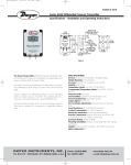
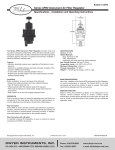
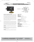
BULLETINF_52.
6/4/03
11:47 AM
Page 1
Bulletin F-52
®
Series RMV Rate-Master Flowmeters
Specifications — Installation and Operating Instructions
Series RMV Rate-Master® Dial-Type Flowmeters provide accurate, dependable measurement of water flows to
20 GPM. Installed in-line, they employ a “target” type element linked to a flexible leaf spring which deflects in proportion to the force generated by the flowing medium.
A magnet attached to the free end of the spring drives
a mating magnet to which the indicating pointer is attached.
Because the spring/magnet assembly is isolated from
the mating magnet/pointer assembly by a wall in the brass
casting, there is no direct mechanical linkage. This means
units can easily withstand over-range flows to 150%
without damage and there is no path for leaks. This construction also allows units to be specially calibrated for
dark and/or opaque liquids which would be impossible
to see with typical rotameter style instruments. Models
are available with 1/2˝, 3/4˝ or 1˝ female connections.
CALIBRATION
All Series RMV flowmeters are calibrated at the factory for
mounting with scale vertical and flow from left to right when
facing unit. They must be used in that position for accurate
readings. If flowmeter was specially calibrated for some
other position, it will be marked accordingly.
These flowmeters will normally retain their original accuracy
for the life of the device. If, at any time you want to check
calibration, do so only with instruments of certified accuracy. Do not attempt to check Dwyer RMV Rate-Master®
flowmeters with other flowmeters piped in a series. Even
minor variations in piping and back pressure can cause a
significant difference in indication. Your Dwyer flowmeter
may be returned to the factory for a calibration check at no
charge. This no-charge check does not include written certification or any repairs necessary to restore proper operation.
DWYER INSTRUMENTS, INC.
P.O. BOX 373 • MICHIGAN CITY, INDIANA 46361, U.S.A.
SPECIFICATIONS
Service: Compatible liquids.
Wetted Materials: Brass, copper, 302 SS, sintered barium ferrite.
Temperature Limits: 20 to 200°F (-6.7 to 93°C).
Pressure Limit: 1000 psig (68.9 bar).
Pressure Drop: 0-5 GPM: 3.2 PSID; 0-10 GPM: 5.3
PSID; 0-20 GPM: 10.4 PSID.
Accuracy: ±2% of full scale.
Size: Diameter dial face 4˝ (101.6 mm).
Process Connections: See Chart.
Maximum Flow: 1.5 x full scale reading.
Weight: 9 Ib (4.08 kg).
Model Number
Range, GPM Water
Connection Size
RMV-1-3
RMV-2-3
RMV-3-3
RMV-1-2
RMV-2-2
RMV-3-2
RMV-1-1
RMV-2-1
RMV-3-1
0-5
0-10
0-20
0-5
0-10
0-20
0-5
0-10
0-20
1" female NPT
1" female NPT
1" female NPT
3
⁄4" female NPT
3
⁄4" female NPT
3
⁄4" female NPT
1
⁄2" female NPT
1
⁄2" female NPT
1
⁄2" female NPT
Phone: 219/879-8000
Fax: 219/872-9057
www.dwyer-inst.com
e-mail: [email protected]
BULLETINF_52.
6/4/03
11:47 AM
Page 2
LOCATION
Select a location where the flowmeter can be easily read
and where the temperature will not exceed 200°F (93°C).
The mounting surface and piping to the flowmeter should
be free from excessive vibration. If pulsing flow or vibration
causes excessive pointer oscillation, contact factory for
ways to provide additional dampening.
PIPING
Inlet Piping: It is good practice to approach the flowmeter
inlet with as few elbows, restrictions, and size changes as
possible. Inlet pipe should be as close to the flowmeter
connection size as practical to avoid turbulence which can
occur with drastic size changes. The length of inlet piping
has little effect on normal pressure-fed flowmeters.
Discharge Piping: Piping on the discharge side should be
at least as large as the flowmeter connection.
MOUNTING
In-Line Mounting: Flowmeter may be installed in-line supported only by the piping. A square wrench surface surrounds the outlet port to aid in assembly.
Surface Mounting: Drill (4) 3/16˝ diameter holes in the
panel using dimensions shown in the drawing below.
Attach with 6-32 machine screws of appropriate length. For
many metal panels the 5/16˝ screws included can be used.
Flush Mounting: If required, re-zero flowmeter before
panel mounting. Provide a 4-3/4˝ (120 mm) opening in
panel. Place flowmeter into opening and attach (4) mounting lugs to rear of case with 6-32 X 5/16˝ machine screws.
Secure unit in place by tightening (4) 6-32 X 3-1/2˝ screws
through the mounting lugs against the rear of the panel.
Zero Setting: The RMV Rate-Master® flowmeter is calibrated and zeroed in a specific (normally vertical) position at
the factory. If the gage is used in any other position, it may
be necessary to adjust the zero setting. Position changes
can aversely affect accuracy.
If re-zeroing is required, hold the brass case firmly with one
hand and turn the grey bezel cover counterclockwise to
remove. Next, lift off the plastic cover. Hold the 5/32˝ diameter brass knob below the pointer axis stationery and adjust
the rectangular brass blade between axis and knob.
Repeat adjustments as necessary until flowmeter reads
exactly zero when held in its intended mounting position.
To replace the cover, align the (2) 1/8˝ slots on the edge with
matching 1/8˝ projections on the case adjacent to the pointer bumpers. Install the bezel ring, hold cover in place with
palm of hand and turn ring clockwise until tight.
POINTER
POINTER AXIS
OPERATION
If flowing media is dirty, install a 50-micron filter upstream
from the flowmeter inlet. After all connections are complete,
introduce flow as slowly as possible to avoid damage. With
liquid flows, it may be necessary to purge air from the system before pointer readings stabilize.
MAINTENANCE
The moving parts of these flowmeters need no routine maintenance or lubrication. The only adjustment is the zero setting which should be checked periodically. Units in need of
repair should be returned to the factory prepaid. Field repair
is not recommended.
BRASS BLADE
ADJUST AS NECESSARY
BRASS KNOB
HOLD STATIONARY
©Copyright 2003 Dwyer Instruments, Inc.
Printed in U.S.A. 6/03
DWYER INSTRUMENTS, INC.
P.O. BOX 373 • MICHIGAN CITY, INDIANA 46361, U.S.A.
FR# 50-440721-00 Rev. 1
Phone: 219/879-8000 www.dwyer-inst.com
Fax: 219/872-9057
e-mail: [email protected]