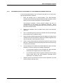
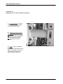
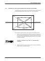
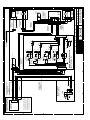
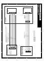
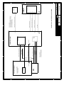
1
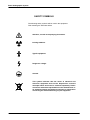
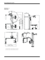
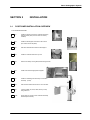
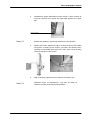
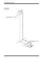
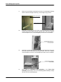
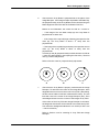
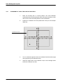
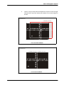
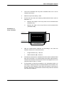
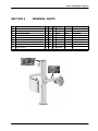
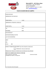
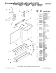
Technical Publication
SM-0521R3
Service Manual
BRS
Basic Radiographic System
STEPHANIX
rue Jean Moulin
Zone Industrielle du Bayon
42150 La Ricamarie
FRANCE
Tel. : 00 33 4 77 47 81 60 ; Fax : 00 33 4 77 37 55 19
0459
Le marquage CE qui se trouve sur ce produit indique que celui-ci est en conformité avec la directive européenne des dispositifs médicaux 93/42/CEE
This product bears a CE marking in accordance with the provisions of the 93/42/EEC MDD dated June 14, 1993.
Basic Radiographic System
Service Manual
REVISION HISTORY
REVISION
DATE
REASON FOR CHANGE
0
April 22, 2003
1
30 March, 2004
2
07 May, 2005
Installation improvements.
3
12 Jul, 2005
New schematics and updated photos.
First edition
Installation and dimensions modified.
This Document is the English original version, edited and supplied by the manufacturer.
The Revision state of this Document is indicated in the code number shown at the bottom of this page.
ADVISORY SYMBOLS
The following advisory symbols will be used throughout this manual. Their
application and meaning are described below.
DANGERS ADVISE OF CONDITIONS OR SITUATIONS THAT
IF NOT HEEDED OR AVOIDED WILL CAUSE SERIOUS
PERSONAL INJURY OR DEATH.
ADVISE OF CONDITIONS OR SITUATIONS THAT IF NOT
HEEDED OR AVOIDED COULD CAUSE SERIOUS PERSONAL
INJURY, OR CATASTROPHIC DAMAGE OF EQUIPMENT OR
DATA.
Advise of conditions or situations that if not heeded or
avoided could cause personal injury or damage to equipment
or data.
Note
SM-0521R3
.
Alert readers to pertinent facts and conditions. Notes represent
information that is important to know but which do not necessarily
relate to possible injury or damage to equipment.
Basic Radiographic System
Service Manual
SAFETY SYMBOLS
The following safety symbols will be used in the equipment.
Their meaning are described below.
Attention, consult accompanying documents.
Ionizing radiation.
Type B equipment.
Dangerous voltage.
Ground.
This symbol indicates that the waste of electrical and
electronic equipment must not be disposed as unsorted
municipal waste and must be collected separately. Please
contact an authorized representative of the manufacturer or
an authorized waste management company for information
concerning the decommissioning of your equipment.
SM-0521R3
Basic Radiographic System
Service Manual
TABLE OF CONTENTS
Section
1
Page
INTRODUCTION . . . . . . . . . . . . . . . . . . . . . . . . . . . . . . . . . . . . . . . . . . . . . . . . . . . . . . . . .
1
1.1
Tools . . . . . . . . . . . . . . . . . . . . . . . . . . . . . . . . . . . . . . . . . . . . . . . . . . . . . . . . . . . . . .
1
1.2
Pre-Installation Checks . . . . . . . . . . . . . . . . . . . . . . . . . . . . . . . . . . . . . . . . . . . . . .
1
2
UNPACKING . . . . . . . . . . . . . . . . . . . . . . . . . . . . . . . . . . . . . . . . . . . . . . . . . . . . . . . . . . . .
3
3
INSTALLATION . . . . . . . . . . . . . . . . . . . . . . . . . . . . . . . . . . . . . . . . . . . . . . . . . . . . . . . . . .
5
1.2
5
4
Positioner Installation overview . . . . . . . . . . . . . . . . . . . . . . . . . . . . . . . . . . . . . . .
ADJUSTMENTS
........................................................
15
4.1
Adjustment tools . . . . . . . . . . . . . . . . . . . . . . . . . . . . . . . . . . . . . . . . . . . . . . . . . . . .
15
4.2
Alignment of X-ray Beam . . . . . . . . . . . . . . . . . . . . . . . . . . . . . . . . . . . . . . . . . . . .
18
4.2.1
Alignment of Light Field with X-ray Field . . . . . . . . . . . . . . . . . . . . . . . . .
22
4.2.2
Perpendicularity Adjustment of X-ray Beam with Image Receptor . . .
25
4.2.3
Centering of X-ray Field and Image Receptor Bucky Assembly . . . . .
27
4.3
Field Size Indicator Test . . . . . . . . . . . . . . . . . . . . . . . . . . . . . . . . . . . . . . . . . . . . .
28
4.4
X-ray Tube or Collimator Replacement . . . . . . . . . . . . . . . . . . . . . . . . . . . . . . . . .
30
4.5
Adjustment of rotation Plate . . . . . . . . . . . . . . . . . . . . . . . . . . . . . . . . . . . . . . . . . .
30
5
RENEWAL PARTS . . . . . . . . . . . . . . . . . . . . . . . . . . . . . . . . . . . . . . . . . . . . . . . . . . . . . .
31
6
MANTEINANCE . . . . . . . . . . . . . . . . . . . . . . . . . . . . . . . . . . . . . . . . . . . . . . . . . . . . . . . . .
33
7
INTERCONNECTION MAPS . . . . . . . . . . . . . . . . . . . . . . . . . . . . . . . . . . . . . . . . . . . . . .
35
SM-0521R3
i
Basic Radiographic System
Service Manual
ii
SM-0521R3
Basic Radiographic System
Service Manual
SECTION 1
1.1
INTRODUCTION
TOOLS
The following hand tools are required for the Installation:
1.2
•
Standard service engineers tool kit.
•
Electric drill motor and assorted bits.
PRE-INSTALLATION CHECKS
Prior to beginning installation it is recommended to inspect the site and verify
that the X-ray room complies with requirements such as:
•
The maximum dimensions and system movements to plan the minimum
space required in the room:
Maximum Height
2500 mm
Maximum Width
1550 mm
Maximum Length
1340 mm
•
Conduits and walls are ready to install the System.
•
Electricity installation:
Power Line (for Collimator Lamp):
24 VAC, 50/60 Hz, 6.5 A
Power Line (for Movement Locks):
24 VDC, 0.2 kVA
ACCORDING TO MDD93/42/CEE, THIS UNIT IS EQUIPPED
WITH EMC FILTERS. THE LACK OF THE PROPER
GROUNDING MAY PRODUCE ELECTRICAL SHOCK TO THE
USER.
SM-0521R3
1
Basic Radiographic System
Service Manual
Illustration 1-1
Dimensions
700
2148
Max. Height = 2500 mm.
Altura Max. = 2500 mm.
Column Max. height = 2240 mm.
Altura Max. Columna = 2240 mm.
Max. Travel = 1400 mm.
Recorrido Max. = 1400 mm.
566
497
610
1795
1400
885
440
707 mm.
SID = 1400 mm.
Max. Width = 1595 mm.
Anchura Max. = 1595 mm.
(*) Dimensions Subject to change depending on the type of tube
(*) Dimensiones sujetas a cambio dependiendo del tipo de tubo
2
SM-0521R3
Basic Radiographic System
Service Manual
SECTION 2
UNPACKING
The Unit is shipped in one box to facilitate transport and installation. Upon
receipt of the X-ray unit and associated equipment, inspect all shipping
containers for signs of damage. If damage is found, notify the carrier or his
agent immediately.
1.
Place the shipping pallet near its final site in the room and remove all its
laterals. Do not discard any packing material such as envelopes, boxes,
bags until all parts are accounted for as listed on the packing list.
AT LEAST THREE PEOPLE ARE REQUIRED TO REMOVE
ALL HEAVY COMPONENTS FROM THE SHIPPING PALLET.
SM-0521R3
2.
When the equipment is unpacked, check part numbers and serial
numbers of each component with its identification labels. Inspect all
pieces for visible damages. If any damaged part is found, repair it or
order its replacement to prevent unnecessary delay in installation.
3.
Verify that all items on the customer order are present.
4.
Leave a working area around equipment until its final installation is
complete.
3
Basic Radiographic System
Service Manual
This page intentionally left blank.
4
SM-0521R3
Basic Radiographic System
Service Manual
SECTION 3
3.1
INSTALLATION
POSITIONER INSTALLATION OVERVIEW
TICK BOXES WHEN DONE
1.--
Install the Support of the Tube--Collimator Assembly
and the Control panel (in some cases it is factory
installed)
2.--
Install the Wall Support at the back of the Column
(the Column laid on the pallet)
3.--
Drill WALL HOLES and anchor the Wall Support .
4.--
Install the Collimator and the X-ray tube.
1
2
4
5.--
Remove the Safety Locking Rod/Central carriage Screw.
5
6
6.--
Install all the counterweight plates supplied.
7.--
Install the Oscillating Grid Assembly or Fixed Grid
Assembly. (level it)
10
8.--
Drill FLOOR HOLES and anchor the unit to the floor.
9.--
Connect cables (HV, Tube, Stator, Bucky or Grid)
and guide them .
10.--
Check levels on Column, Tube-Collimator Assembly
and Receptor Assembly.
9
7
SM-0521R3
5
Basic Radiographic System
Service Manual
Note
.
Perform Installation following the order described below.
DO NOT REMOVE SAFETY LOCKING ROD FROM THE
COUNTERWEIGHT CARRIAGE AND/OR THE CENTRAL
CARRIAGE SCREWS (2)
BEFORE SPECIFICALLY
INSTRUCTED IN THIS DOCUMENT.
Note
.
Due to packaging requirements, some Units may not include the
Tube Collimator Assembly and the Control panel factory
pre-installed. If that is the case, follow steps 1 and 2, if not, go to
step 3.
1.
Assemble the Support of the Tube-Collimator Assembly to the Upper
area of the Swivel Arm using the four Safety Screws installed in the Arm.
SAFETY SCREWS
SUPPORT OF TUBE-COLLIMATOR ASSEMBLY
2.
Assemble the Control Panel in the Support with the two screws, washers
and nuts attached to the Control Panel.
CONTROL PANEL
SUPPORT OF TUBE-COLLIMATOR ASSEMBLY
SCREWS, WASHERS AND NUTS
6
SM-0521R3
Basic Radiographic System
Service Manual
3.
Assemble the Upper Wall Support to the Column. Lift the Column as
much as necessary as to mount the Upper Wall Support in its upper
part.
SAFETY SCREWS
Note
Note
SM-0521R3
.
.
At least two people are required to perform the next operation.
4.
Position the column against the wall on its final site in the room. While
one person is holding up the Column, the other one should level it
vertically on both lateral sides and on the front. Also use the leveling
screws at the base of the column.
5.
Mark its anchoring positions on the wall (not to the floor yet).
Distances shown on Illustration 3-1 may also be taken as
reference to mark the anchoring holes position.
7
Basic Radiographic System
Service Manual
160
Illustration 3-1
Drill Template
FOUR WALL MOUNTING HOLES
1839
FOR SCREWS 8 mm.
FOUR FLOOR MOUNTING HOLES
FOR SCREWS10 mm.
8
SM-0521R3
Basic Radiographic System
Service Manual
6.
Move the Column and prepare the anchorages.
BEFORE ANCHORING THE UNIT, CHECK THAT THE WALL
AND THE ANCHORING SYSTEM ARE STRONG ENOUGH
(2000 NEWTON TRACTION FORCE) TO ENSURE A SAFE
INSTALLATION. SOME NON BRICK WALLS MAY REQUIRE
ADDITIONAL ANCHORAGE INSTALLATION.
7.
Drill holes and anchor the Wall Support. Make sure the Column is firmly
anchored and leveled at front, sides and base.
8.
Install the X-ray Tube in the Upper Support of the Column using the
Collimator Adaptation Ring and its four Safety Screws (Allen).
9.
Before installing the Collimator, unscrew the same number of turns the
four Centering Adjustment and Safety Screws (Allen) to allow the
Collimator installation in the Collimator Adaptation Ring. Adjust the
Collimator Blades to their widest setting and carefully install the
Collimator centering it with the X-ray Tube window.
Tighten carefully the four Centering Adjustment and Safety Screws
(Allen) equally (same number of turns) until Collimator is centered and
held firmly on the Coupling Ring (support). (Also, refer to Collimator
Manual).
Illustration 3-2
Installation of X-ray Tube and Collimator
X-RAY TUBE COVER
X-RAY TUBE CABLE
CENTERING/ADJUSTMENT SCREWS
COLLIMATOR COVER
COLLIMATOR CABLE
10.
SM-0521R3
Remove the X-ray Tube and Collimator covers and connect the wires
from the upper harness to the X-ray Tube and Collimator according to
their identification (refer to 54301065).
9
Basic Radiographic System
Service Manual
11.
Remove now the Safety Locking Rod from the Counterweight Carriage
and the Central Carriage Screws (2). The carriage may go down.
Safety locking Rod
Central Carriage Screw
12.
Add all the counterweigh pieces to both entrances at the back side of the
Column and secure them with the provided nuts. The unit is factory
counterweighted, so the counterweights provided are to be installed.
Counterweight entrances
at Column Back
13.
Add all the counterweigh pieces to both entrances at the back side of the
Arm and secure them with the provided nuts. The unit is factory
counterweighted, so all the counterweights provided are to be installed.
Counterweight entrances
at Arm Back
14.
10
Now install the Oscillating Grid Assembly or the Fixed Grid
Assembly. Follow steps 14 to 17 for Oscillating Grid Assembly or steps
18 to 21 for Fixed Grid Assembly.
SM-0521R3
Basic Radiographic System
Service Manual
15.
Oscillating Grid Assembly installation:Take out Table-Top of the
Oscillating Grid Assembly -- Four screws at the corner of the Oscillating
Grid Assembly.
Table-Top
Corner Screw
16.
Install the Oscillating Grid Assembly in the Swivel Arm with the 2 sets of
screws (4 screws in each set). A set of gauges (included in the package)
can be installed for perpendicularity adjustment.
Oscillating Grid Assembly Installation Screws
17.
Connect J1 (only for Oscillating Grid Assembly with motorized Grid), J2
and GND from the Harness to the Oscillating Grid Assembly.
GND
J1
18.
SM-0521R3
Reinstall the Oscillating Grid Assembly Table-top.
11
Basic Radiographic System
Service Manual
19.
Fixed Grid Assembly Installation: Remove the Safety Screws installed
in the Fixed Grid Assembly.
20.
Remove the Back Cover of the Swivel Arm end.
21.
Install the Fixed Grid Assembly in the Swivel Arm with the Safety Screws
previously removed. (Before connect J2).
22.
Level the Assembly with the leveling screws and re-install the Back
Cover.
Leveling Screws
Safety Screws
J2
Back Cover at Swivel Arm End
23.
Connect the cables from the main harness (Stator, Bucky, Power Line,
Collimator and ground (GND) cables routed directly from the Column) to
the Generator (for these connections refer to Interconnection Map
54301065 and also Generator Service Manual).
24.
Connect directly the ground cables (GND) from the Column to the Main
ground stud (GND) of the Generator.
25.
Connect HV Cables of the X-ray Tube.
Terminal Pins of HV Cables are extremely delicate and they
are easily damaged. Take particular care to handle them
carefully. Make sure that they remain straight and that the
splits in the pins are open (parallel to sides).
12
SM-0521R3
Basic Radiographic System
Service Manual
Prepare the High Voltage terminals that will be installed in the X-ray Tube
receptacles. Apply Silicone Paste over the entire surface of the Plug
including the Pins.
Carefully connect cables to their related receptors of the Tube and fix
their nuts tightly.
26.
Fasten HV cables to lateral side of Pivoting Arm with the clamp on the
carriage of the Tube Collimator Assembly. Give the cable length enough
to enable movements of the of Pivoting Arm.
Fasteners
H V Cables
Note
Note
SM-0521R3
.
Tube HV Cables may also be tied up to a ceiling pole to avoid
collisions and to easy movements of the system.
27.
Mark and drill the anchoring positions on the floor. Check leveling again
in different sides of the unit and correct if necessary before fixing the unit
definitely.
28.
Anchor the Column to the floor.
.
Distances shown on Illustration 3-1 may also be taken as
reference to mark the anchoring holes position.
29.
Snap in the decorative base of the Columm (pressing it).
30.
Turn the system on and check that all controls and movements operate
correctly.
13
Basic Radiographic System
Service Manual
This page intentionally left blank.
14
SM-0521R3
Basic Radiographic System
Service Manual
SECTION 4
4.1
ADJUSTMENTS
ADJUSTMENT TOOLS
The following special Tools have been used for adjustment of the X-ray System
(these tools are not included with the System):
SM-0521R3
•
Collimator Test Tool (Model RMI 161B9).
•
Beam Alignment Test Tool (Model RMI 162A).
•
SID Test Stand Tool (Inside Case: RMI Model 175).
•
Light Meter (Standard).
15
Basic Radiographic System
Service Manual
Illustration 4-1
Checkings overview
1 Check /Correct levels of Column and tube
2 Check /Correct levels of Receptor
Fixed Grid Assembly
Leveling Screws
Oscillating Grid Assembly
3 Check / Correct alignment of the light field with the X-ray field
CENTERING ADJUSTMENT
SCREWS
16
SM-0521R3
Basic Radiographic System
Service Manual
Illustration 3-1 (cont)
Checkings Overview
4 Check / Correct the perpendicular adjustment
of the X-Ray Beam with the Image Receptor
A
B
C
CENTERING ADJUSTMENT
SCREWS
Fixed Grid Assembly
Leveling Screws
Oscillating Grid Assembly
5
Check / Correct centering of X-Ray field and
Image Receptor
(same adjustments as step 4)
DEVIATION
SM-0521R3
6
Field Size Indicator Test
7
Collimator Lamp Brightness Test
17
Basic Radiographic System
Service Manual
4.2
ALIGNMENT OF X-RAY BEAM
1.
Check with a level the vertical/horizontal position of the Column. If
necessary, modify the position of the Column with the screws attached
to the Base of the Column, a correct installation starts with a good
leveling of the column.
Levels
2.
Check the level of the Tube-Collimator Assembly. The mechanical
installation provides a levelled Assembly, anyway check parallelism. If
necessary reinstall the Tube-Collimator Assembly. (Refer to installation
section).
3.
Check the Receptor, first in horizontal position (thorax), then in vertical
position (Undertable). If necessary, move up or down the Receptor
assembly with the Receptor Assembly leveling screws.
4.
Place the Pivoting Arm in vertical position. The Tube-Collimator
Assembly has to be perfectly aligned with the Receptor Assembly. Check
with a level correct horizontal position of both assemblies.
Illustration 4-2
Vertical Position of Pivoting Arm with Alignment Tools
18
SM-0521R3
Basic Radiographic System
Service Manual
5.
Turn on Collimator light and center the Collimator in relation to the
Receptor Table-Top. Horizontal and transversal position of the light axes
projected by the Collimator Lamp must be in line with the axes or film
sizes marked on the Table-Top.
If needed, modify Collimator position by carefully unscrewing and
screwing the four Centering Adjustment and Safety Screws (Allen) of
Collimator.
Illustration 4-3
Collimator Screws
CENTERING ADJUSTMENT AND SECURITY SCREWS
SM-0521R3
6.
Position the Collimator Test Tool (RMI model 161B) on the Receptor
Table-Top.
7.
Turn on Collimator light and by means of the Collimator Control Knobs,
center the Collimator Test Tool with the light axes projected by the
Collimator Lamp.
19
Basic Radiographic System
Service Manual
8.
Adjust the Light Field of the Collimator Lamp to the rectangle drawn
inside the Collimator Test Tool.
9.
Place centered the Beam Alignment Test Tool (RMI model 162A) on the
Collimator Test Tool.
Illustration 4-4
Alignment Test Tools
BEAM ALIGNMENT TEST TOOL -- RMA MODEL 162A
COLLIMATOR TEST TOOL -- RMA MODEL 161B
10.
Load Cassette film Tray with cassette film 24x30 and insert it.
11.
Make an exposure at 60 kVp / 5 mAs.
12.
Process film and:
a.
Check that the X-ray Field falls just within the image of the inner
rectangle of the Collimator Test Tool.
If an edge of the X-ray Field falls out of the inner rectangle means
a misalignment of the Light Field respect to the X-ray Field. The
maximum misalignment allowed is 2 % of SID (for SID 1.4m = 2.8
cm tolerance).
Refer to Section 4.2.1 for alignment of Light Field with X-ray Field.
20
SM-0521R3
Basic Radiographic System
Service Manual
b.
Check that the X-ray Beam is perpendicular to the plane of the
Image Receptor. If the Image receptor is parallel to the Table-Top,
the perpendicularity of the X-ray Beam can be checked using the
Beam Alignment Test Tool with the Collimator Test Tool.
Based on next illustration, the criteria for SID at 1.4 meter is:
-- If the image of the two balls overlap (A) the X-ray Beam is
perpendicular to within 0.5o.
-- If the image of the top ball (larger shadow) intercepts the first
circle (B), the X-ray Beam is about 1.5o away from the
perpendicular.
-- If the image of the top ball (larger shadow) intercepts the second
circle (C), the X-ray Beam is about 3o away from the
perpendicular.
In cases (A) and (B) perpendicularity is within tolerance for SID at
1 meter (top ball is within or intercepting the first circle). The third
case (C) needs readjustment.
Refer to Section 4.2.2 for perpendicularity adjustment.
A
c.
B
C
Check that the X-ray Beam is properly centered with the Image
Receptor. To determine the center of the Image Receptor, draw
diagonal lines from corner to corner of the X-ray Film. (Alternately,
the film can be folded in half and creased at the center). The two
lines will cross in the center of the Image Receptor (film). Then
draw diagonal lines from the corners of the imaged X-ray Field.
If the center of the X-ray Field and Image Receptor is the same,
the diagonals of both sets of lines should cross at the same point.
The maximum misalignment allowed is 2 % of SID (for SID 1.4m
= 2.8 cm tolerance).
Refer to Section 4.2.3 for centering of X-ray Field and Image
Receptor.
SM-0521R3
21
Basic Radiographic System
Service Manual
4.2.1
ALIGNMENT OF LIGHT FIELD WITH X-RAY FIELD
1.
Place the Pivoting Arm in vertical position. The Tube-Collimator
Assembly has to be perfectly aligned with the Receptor Assembly. Check
with a level correct horizontal position of both assemblies.
2.
Position the Collimator Test Tool (RMI model 161B) on the Receptor
Table-Top.
3.
Turn on Collimator light and center the Collimator Test Tool with the light
axes projected by the Collimator Lamp.
4.
Adjust the Light Field of the Collimator Lamp to the rectangle drawn
inside the Collimator Test Tool.
COLLIMATOR TEST TOOL
22
SM-0521R3
Basic Radiographic System
Service Manual
5.
Check on the processed film the adjustment required to meet the Light
Field with the X-ray Field. Identify the deviation on the axes imaged on
the film.
PROCESSED FILM
COLLIMATED LIGHT FIELD
COLLIMATED X-RAY FIELD
LIGHT FIELD MISALIGNMENT
PROCESSED FILM
COLLIMATED LIGHT FIELD = COLLIMATED X-RAY FIELD
GOOD FIELDS ALIGNMENT
SM-0521R3
23
Basic Radiographic System
Service Manual
6.
Do not remove the Collimator Test Tool from its original position and
adjust the Light Field by moving the Collimator Unit and/or the Collimator
Lamp.
a.
Collimator Lamp must be ON during Light Field adjustment.
b.
Modify Collimator position by carefully unscrewing and screwing
the four Centering Adjustment and Safety Screws (Allen) until the
Light Field coincides with the axes reference imaged (numbers
and dots) on the processed film.
Illustration 4-5
Collimator Screws
CENTERING ADJUSTMENT AND SECURITY SCREWS
c.
7.
24
If adjustment is still necessary, modify position of Collimator Lamp
(refer to Collimator Manual).
Repeat exposure and procedure until the result is satisfactory. The
maximum misalignment allowed is 2 % of SID (for SID 1.4m = 2.8 cm of
tolerance).
SM-0521R3
Basic Radiographic System
Service Manual
4.2.2
PERPENDICULARITY ADJUSTMENT OF X-RAY BEAM WITH IMAGE RECEPTOR
In case that perpendicularity is out of tolerance (top ball is out of first circle),
adjust perpendicularity as follows:
1.
Place the Pivoting Arm in vertical position. The Tube-Collimator
Assembly has to be perfectly aligned with the Receptor Assembly. Check
with a level correct horizontal position of both assemblies.
The Receptor Assembly is factory adjusted (slightly up) and it is
recommended do not perform any additional correction. During
procedure, it must be horizontally placed at 0o (check position with a level
and with its indicator plate).
2.
Position the Collimator Test Tool (RMI model 161B) on the Receptor
Table-Top.
3.
Turn on Collimator light and center the Collimator Test Tool with the light
axes projected by the Collimator Lamp.
4.
Place centered the Beam Alignment Test Tool (RMI model 162A) on the
Collimator Test Tool and observe if shadow of the Beam Alignment Test
Tool is projected in equal proportion around it.
5.
Check on the processed film the adjustment required to center the top
ball mark. Shadow around the Beam Alignment Test Tool can also help
to make a first correction.
6.
Loosen slightly the four Safety Screws (Allen M8) of the Tube-Collimator
Assembly. If required, perform the following adjustments:
7.
SM-0521R3
G
For horizontal correction move horizontally the Tube-Collimator
Assembly before tightening the four Safety Screws.
G
For vertical correction loosen or tighten carefully the four Leveling
Screws (Allen M6) of the Tube-Collimator Assembly before
tightening the four Safety Screws.
Repeat exposure and procedure until the result is satisfactory (top ball
must be inside of the first circle).
25
Basic Radiographic System
Service Manual
Illustration 4-6
Adjustments in the Tube-Collimator Assembly
1.-- Leveling Screws: The TubeCollimator Assy. moves slightly
up or down from one side.
1
2b
3
2.-- Positioning screws and Fix-
ing Screws:
2a: Loose first the Fixing Screws,
then adjust the tube-collimator
with the positioning screws
2b: then tighten the Fixing
Screws.
2a
3.-- Shims (factory installed/ad-
justed, and extra units included
in package). These plates can be
added or removed in order to extend/reduce the length of the
Tube-Collimator Assembly
--.
26
SM-0521R3
Basic Radiographic System
Service Manual
4.2.3
CENTERING OF X-RAY FIELD AND IMAGE RECEPTOR RECEPTOR ASSEMBLY
The error between centers of the X-ray Field and the Image Receptor should
not be greater than 2% of the SID. (for SID 1.4m = 2.8 cm tolerance).
CENTER OF THE IMAGE
CENTER OF THE X--RAY FILM
DEVIATION
If the deviation is greater than 2% of SID, perform the following procedure:
1.
Check on the processed film the correction required for centering the
X-ray Field with the Image Receptor. Adjustments will be performed as
the same way described for Perpendicularity correction, so only re-adjust
it if really is necessary.
Centering adjustments may affect to perpendicularity
corrections.
2.
SM-0521R3
Repeat exposure and check centering until the result is satisfactory
(centers position are within tolerance).
27
Basic Radiographic System
Service Manual
4.3
FIELD SIZE INDICATOR TEST
Note
28
.
Before starting with the Field Size Indicator Test, the Alignment of
X-Ray Beam Test, the Alignment of Light Field with X-Ray Field
Test and the SID Indicator Test should be performed.
1.
Place the Pivoting Arm in vertical position. The Tube-Collimator
Assembly has to be perfectly aligned with the Receptor Assembly. Check
with a level correct horizontal position of both assemblies.
2.
Open the Collimator blades to set a Field Size of 24 x 30 cm for SID
1,4 m.
3.
Turn on the Collimator Light and center the Collimator in relation to the
Receptor Table-Top. Horizontal and transversal position of the light axes
projected by the Collimator Lamp must be in line with the axes or Film
Size marked on the Table-Top.
SM-0521R3
Basic Radiographic System
Service Manual
4.
Load on the Cassette Film Tray with a Cassette Film of 35 x 43 cm
centered and insert it.
5.
Make an exposure at 60kVp, 1mAs.
6.
Process film and check the following measurements known (refer to
Illustration 4-7):
a.
Measure the length of the X-ray Field on the Processed Film
(identified as L)
b.
Measure the width of the X-ray Field on the Processed Film
(Identified as W)
Illustration 4-7
X-ray Field Size
X-RAY FIELD SIZE ON THE FILM
WIDTH DIMENSION (W)
FILM 35x43 cm
PROCESSED FILM
LENTH DIMENSION (L)
7.
SM-0521R3
With the measurements obtained and according to the field size
indication selected, the results should be:
G
Length dimension (L) = 300 mm
G
Width dimension (W) = 240 mm
8.
The difference between the indicated Field Size and the obtained Field
Size may not exceed 1.5 % (rejection limit) of the SID in either direction.
Therefore the deviation in any direction should not be higher than 21 mm
(rejection limit) for SID at 1.4 meter.
9.
If the deviation of Field Size Indication is out acceptance limits, it is
necessary to readjust the index of Collimator Blades Control Knobs. For
that, loosen each Collimator Control Knob and position it according to
deviation. Repeat the complete tests until the X-Ray Field Size selected
(24 x 30 cm) is obtained.
29
Basic Radiographic System
Service Manual
4.4
X-RAY TUBE OR COLLIMATOR REPLACEMENT
Note
.
This section only applies to systems where the X-ray Tube or the
Collimator has to be replaced by a new different X-ray Tube or
Collimator (different weight) or when the Swivel arm is not
vertically balanced.
1.
Place swivel Arm in horizontal position.
2.
Remove the top cover of the Tube-Collimator Assembly Support.
3.
Add or remove counterweight plates until the Arm is balanced.
Counterweight entrances
at Arm Back
4.
4.5
Re-install the top cover.
ADJUSTMENT OF ROTATION PLATE
Note
.
This section only applies to systems where the rotation plate does
not match with the real angle.
1.
Place swivel Arm in horizontal position.
2.
Loose Safety Screws and adjust correct angle with a level.
3.
Tighten Safety Screws.
CENTERING ADJUSTMENT AND SECURITY SCREWS
STEEL CABLE
30
SM-0521R3
Basic Radiographic System
Service Manual
SECTION 5
Item
RENEWAL PARTS
Designation
Qty
FRU
Rep
Mfg. Ref.
Second Ref.
Remarks
Positioner
1
Switch button (black)
3
2
N
50613013
2
Handle
3
2
Y
S02.05.012
3
Solenoid 24 VDC
1
1
Y
52301006
4
Electrobrake 24 -- 35 VDC (positive)
5
1
N
52301011
5
Basic Mill. Control PCB
1
1
Y
A3510--03
6
Bucky Midwest
1
1
Y
6685-01
7
Collimator
1
2
N
6693--06
8
Lamp (Collimator)
1
2
N
54203005
4
5
3
2
1
7
1
8
6
1
7
SM-0521R3
31
Basic Radiographic System
Service Manual
This page intentionally left blank.
32
SM-0521R3
Basic Radiographic System
Service Manual
SECTION 6
MAINTENANCE
The Optima BRS has been designed as a long term X--ray positioner with
minimum maintenance.
The mechanical parts of the Optima BRS require a yearly basis service
maintenance from the installation date in the following way:
Visual Check: Covers, Pushbuttons, Table-top, Receptor Assembly, Steel
Cables appareance (from the Column Slot side), connectors and electrical
cables.
Functional Check: Push-buttons, movements of the carriage and arm, cassette
tray, perform an exposure and check correct alignment of film, Collimator and
Collimator light (refer to Section 4).
Yearly Functional Check
ITEM
Push-buttons
Movement of Carriage
Visual Check, correct contact and corresponding movement.
Check complete travel of carriage, it should be soft and noiseless
Movement of Arm
Check complete angle travel of the Arm, it should be soft and noiseless.
Both Steel Cables
Move carriage to the lowest position and check appareance of both steel cables from the side slot
of the column. Check connection plate and disassembly top cover to check the whole cable travel.
They should be in without stranded or broken hairs.
Cassette Tray
Collimator and Tube
SM-0521R3
ACTION
Check correct positioning inside Receptor assembly, correct clamping of film.
Refer to Section 4 in this Manual and Generator maintenance Section.
33
Basic Radiographic System
Service Manual
This page intentionally left blank.
34
SM-0521R3
Basic Radiographic System
Service Manual
SECTION 7
INTERCONNECTION MAPS
Refer to the following maps for details of the wire connections.
SM-0521R3
•
Optima BRS-Who interconnections . . . . . . . . . . . . 54301083
•
BRS System . . . . . . . . . . . . . . . . . . . . . . . . . . . . . . . . IM-339
35
Basic Radiographic System
Service Manual
This page intentionally left blank.
36
SM-0521R3
A
24 V
0V
5
3
6
2
4
1
TIMER
+
0V
24 V
Manguera Colimador
(Collimator Cable)
A3111-XX
GND Cable
0 VDC
+24 VDC
COLIMADOR Ralco
(Ralco Collimator)
SW
LAMP
NOTA.- Para modelos de Generador Alto,
conectar el Cable Alimentación a la regleta
TS1 (+24 VDC aTS1-31, 0 VDC a TS1-32, 24
VAC a TS1-19, y 0 VAC a TS1-20).
NOTE.- For Tall Generator models, connect
the Supply Cable to terminal strip TS1 (+24
VDC to TS1-31, 0 VDC to TS1-32, 24 VAC to
TS1-19, and 0 VAC to TS1-20)
3
4
6
5
TB7
Manguera Alimentación Frenos
(Locks Supply Cable)
A7622-XX
B
B
+24V
W1
SET
W1-B
K3
ROT
K2
VERT
8
7
5
6
16
1
5
12
16
1
5
12
8
9
16
1
5
12
R8, 1K
R7, 1K
R6, 1K
CR10
1N4007
CR7
1N4007
CR4
1N4007
CR1
1N4007
VERT LOCK
K4
TELESCOPIC
3
1
4
2
8
9
8
9
K1
LONG
Connection Cable
( A6773-01)
CR2
1N4007
C
C
REV
TP1
GND
CR9
1N4148
CR8
1N4148
ISSUED BY
R5
1K
CR6
1N4148
CR5
1N4148
D
DATE
D
NAME
REVISED
16/03/04
01/01/04
DATE
1/2
SHEET / OF
Collimator
Panel Cable
( A7653-01)
VERTICAL CONTROL
ROTATION CONTROL
GND
ROT SOLENOID
+24 VDC
4
3
2
1
TS2
2
1
4
3
5
TS4
COLLIMATOR
PANEL
ROTATION
VERTICAL
COLUMN
PANEL
Solenoid Cable
( A7621-01)
CR1
1N5408
ROT
SOLENOID
ROTATION
VERTICAL
BUCKY
PANEL
Bucky
54301083
E
REV
1
2
3
4
E
INTERCONEXIONES OPTIMA BRS-WHO
(OPTIMA BRS-WHO INTERCONNECTIONS)
Vert/Rot Cable
( A7654-01)
3
2
1
Bucky Panel Cable
( A7655-01)
Optima Bucky Cable
( A3342-01)
J2
SEDECAL
A.DIAZ
DRAWING F.GARCIA
C5
470 uF
50V
7
8
9
10
11
12
1
2
3
4
5
6
J1
J1
Control Cable
( A7620-01)
Bucky Cable ( A3343-01)
+24V
CR3
1N4148
CR2
1N4148
to Generator
(see sheet 2)
DESCRIPTION
TP2
+24V
C4
100 uF
35V
R4
511
+24V
C3
100 uF
35V
R3
160
2w
+24V
C2
100 uF
35V
R2
511
+24V
C1
100 uF
35V
R1
511
+24V
BASIC MIL CONTROL board
(A3510-03-rev. A)
1
2
3
4
5
6
7
8
9
10
11
12
J2
6
5
4
3
2
1
TS1
A
1
2
3
4
Tarjeta Frenos
(Locks Board)
GENERADOR COMPACT
(COMPACT GENERATOR)
A
B
1
2
3
4
9
8
7
6
5
4
3
2
1
A
7
2
3
1
4
6
5
TS1
Añadir Puente
(Add Jumper)
ARMARIO GENERADOR
(GENERATOR CABINET)
Conector IC puede ser J1, J2, o J3,
dependiendo de la Cámara Ionización
seleccionada.
(Connector IC could be J1, J2, or J3,
depending on the Ion Chamber
selected)
J5
Tarjeta AEC ADAPTATION
(AEC ADAPTATION Board)
A
C
GND
0 VAC
115/220 VAC
BUCKY 1 DR
BUCKY 1 MOTION RTN
BUCKY 1 MOTION
MANGUERA BUCKY (BUCKY CABLE)
(A3343-01)
B
C
Nota.- Este plano es aplicable cuando se utilize el bucky
y/o la cámara ionización.
Note.- This drawing is applicable when using the bucky
and/or the ion chamber.
Shield
GND
+12 VDC
-12 VDC
FLD3 DR (RIGHT)
IC OUTPUT
STRT DR (RESET)
FLD2 DR (CENTER)
FLD1 DR (LEFT)
MANGUERA CAMARA IONIZACION (ION CHAMBER CABLE)
(A3253-XX)
REV
Usar la Manguera Cámara Ionización A3234-02 cuando no se utiliza la tarjeta AEC ADAPTATION.
Ver esquema I/F-003 para interconexiones.
(Use Ion Chamber Cable A3234-02 when the AEC ADAPTATION Board is not used. See I/F-003
schematic for interconnections)
B
DESCRIPTION
ISSUED BY
6
5
4
3
2
DATE
J1
1
D
16/03/04
A.DIAZ
REVISED
SEDECAL
DATE
01/01/04
NAME
F.GARCIA
DRAWING
Cable Bucky Optima
(Optima Bucky Cable)
(A3342-01)
Shield
Shield
OPTIMA BRS
D
2/2
SHEET / OF
6
8
4
3
2
1
9
8
7
6
5
4
3
2
1
REV
1
2
3
4
E
INTERCONEXIONES OPTIMA BRS-WHO
(OPTIMA BRS-WHO INTERCONNECTIONS)
54301083
Bucky
CAMARA IONIZACION
(ION CHAMBER)
E
1
2
3
4
A
X-RAY
TUBE
COLLIMATOR
See schematic 54301083
for interconnections
A
C
Chassis GND
BRS with FIXED GRID
A
TS1
B
Note 2.- Cable code:
A3052-XX for only Low Speed
A7014-XX for Low/High Speed
ANODE CABLE
CATHODE CABLE
TUBE STATOR CABLE (See Note 2)
GND CABLE (A6383-XX)
COLLIMATOR CABLE (A3111-XX)
CABLE ASSEMBLY
LOCKS SUPPLY CABLE (A7622-XX)
B
TS2
A
C
C
Chassis GND
TB7
TB7
HV
TANK
LOCKS BOARD
GENERATOR CABINET
C
REV
DESCRIPTION
TS1/TS3
J3
J2
AC LINE
J2
J3
J1
ATP CONSOLE BOARD
GENERATOR
CONSOLE
VAC SUPPLY
E
ISSUED BY
DATE
D
07/07/05
A.DIAZ
REVISED
SEDECAL
DATE
07/07/05
NAME
F.GARCIA
DRAWING
1/3
SHEET / OF
E
BRS SYSTEM
IM - 339
THIS SHEET ONLY APPLIES TO BRS with FIXED GRID
GND CABLE
INTERFACE CABLE (A7069-XX)
COMMUNICATION CABLE (A7022-XX)
POWER CABLE (A7021-XX)
GENERATOR SUPPLY CABLE (See Note 1)
Note 1.- Cable code:
A8410-01 for Compact Generator - single phase
A8411-01 for Compact Generator - three phase
A8412-01 for Battery Generator
A8413-01 for Capacitor Generator
D
REV
1
2
3
4
1
2
3
4
X-RAY
TUBE
BUCKY
COLLIMATOR
A
Chassis GND
See schematic 54301083
for interconnections
A
C
BRS with OSCILLATING GRID
A
J1
TS1
B
Note 2.- Cable code:
A3052-XX for only Low Speed
A7014-XX for Low/High Speed
ANODE CABLE
CATHODE CABLE
TUBE STATOR CABLE (See Note 2)
GND CABLE (A6383-XX)
BUCKY CABLE (A3343-XX)
COLLIMATOR CABLE (A3111-XX)
CABLE ASSEMBLY
LOCKS SUPPLY CABLE (A7622-XX)
B
TS2
TS1
A
C
Chassis GND
TB7
TB7
C
HV
TANK
LOCKS BOARD
GENERATOR CABINET
C
TS1/TS3
J3
J2
AC LINE
REV
DESCRIPTION
J2
J3
J1
ATP CONSOLE BOARD
GENERATOR CONSOLE
VAC SUPPLY
E
ISSUED BY
DATE
D
07/07/05
A.DIAZ
REVISED
SEDECAL
DATE
07/07/05
NAME
F.GARCIA
DRAWING
2/3
SHEET / OF
E
BRS SYSTEM
IM - 339
THIS SHEET ONLY APPLIES TO BRS with OSCILLATING GRID
GND CABLE
INTERFACE CABLE (A7069-XX)
COMMUNICATION CABLE (A7022-XX)
POWER CABLE (A7021-XX)
GENERATOR SUPPLY CABLE (See Note 1)
Note 1.- Cable code:
A8410-01 for Compact Generator - single phase
A8411-01 for Compact Generator - three phase
A8412-01 for Battery Generator
A8413-01 for Capacitor Generator
D
REV
1
2
3
4
1
2
3
4
X-RAY
TUBE
A
BUCKY
ION CHAMBER
(Preamplifier)
COLLIMATOR
See schematic 54301083
for interconnections
Chassis GND
A
C
J1
TS1
BRS with OSCILLATING GRID and AEC
A
B
Note 2.- Cable code:
A3052-XX for only Low Speed
A7014-XX for Low/High Speed
ANODE CABLE
CATHODE CABLE
TUBE STATOR CABLE (See Note 2)
GND CABLE (A6383-XX)
BUCKY CABLE (A3343-XX)
AEC CABLE (A3253-XX)
COLLIMATOR CABLE (A3111-XX)
CABLE ASSEMBLY
LOCKS SUPPLY CABLE (A7622-XX)
B
TS2
TS1
LOCKS BOARD
A
C
Chassis GND
J1/J2/J3
C
J4
HV
TANK
See schematic IM-010
AEC ADAPTATION BOARD
TB7
TB7
GENERATOR CABINET
C
REV
GND CABLE
INTERFACE CABLE (A7069-XX)
COMMUNICATION CABLE (A7022-XX)
POWER CABLE (A7021-XX)
AEC INTERFACE CABLE (A3251-01)
GENERATOR SUPPLY CABLE (See Note 1)
J2
J3
J1
J5
ATP CONSOLE BOARD
GENERATOR CONSOLE
VAC SUPPLY
E
ISSUED BY
DATE
D
07/07/05
A.DIAZ
REVISED
SEDECAL
DATE
07/07/05
NAME
F.GARCIA
DRAWING
3/3
SHEET / OF
E
BRS SYSTEM
IM - 339
THIS SHEET ONLY APPLIES TO BRS with OSCILLATING GRID and AEC
DESCRIPTION
TS1/TS3
J3
J2
AC LINE
Note 1.- Cable code:
A8410-01 for Compact Generator - single phase
A8411-01 for Compact Generator - three phase
A8412-01 for Battery Generator
A8413-01 for Capacitor Generator
D
REV
1
2
3
4