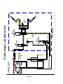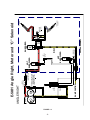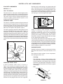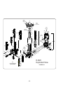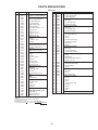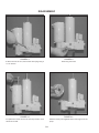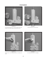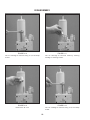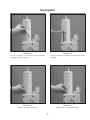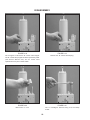
1
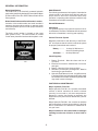
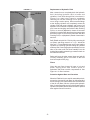
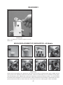
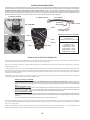
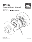
FORM NO. 1-822R1
May 2011
E-58H
power unit
service manual
Meyer Products LLC
18513 Euclid Ave. • Cleveland, Ohio 44112-1084
Phone 486-1313 (Area Code 216)
www.meyerproducts.com• email [email protected]
© 2011 Printed in the U.S.A.
FOREWARD
This Service Manual includes complete information for servicing the following Electro Lift® Units:
E-58H
IMPORTANT: Maintenance and repairs must be performed with the moldboard on the
ground.
The information is grouped according to the type of work being performed, such as diagnosis and
testing, disassembly and reassembly. Special tools and specifications are also included in this manual.
All information, illustrations and product descriptions contained in this manual are correct at publication
time. We do, however, reserve the right to make changes at any time without prior notice.
MEYER PRODUCTS INC.
SECTION INDEX
Section Number
Section Title .....................................................
0
GENERAL INFORMATION AND
MAINTENANCE ........................................................
GENERAL DESCRIPTION AND
THEORY OF OPERATION ........................................
DIAGNOSIS .............................................................
REPAIR PROCEDURE ..............................................
CONTROLLER TROUBLESHOOTING ....................
SPECIFICATIONS .....................................................
1
2
3
4
5
Page
1
4
14
20
38
39
Meyer Products Inc. reserves the right, under its continuing product improvement program, to change construction or
design details, specifications and prices without notice or without incurring any obligation.
SECTION 0
- GENERAL INFORMATION AND MAINTENANCE
CONTENTS
GENERAL INFORMATION ..................................................
2
•
MODEL IDENTIFICATION ....................................................
2
•
MODEL IDENTIFICATION AND
SERIAL NUMBER LOCATION ..............................................
2
•
MOTOR IDENTIFICATION ...................................................
2
MAINTENANCE ...................................................................
2
•
GENERAL MAINTENANCE ...................................................
2
•
CLEANLINESS .................................................................
2
•
VEHICLE ELECTRICAL SYSTEM ...........................................
2
•
CHECK REGULARLY ........................................................
2
POST-SEASON MAINTENANCE ...........................................
2
•
MEYER HYDRAULIC FLUID M-1 .........................................
2
•
REPLACEMENT OF HYDRAULIC FLUID ...................................
3
•
FILTERS ........................................................................
3
PROTECTION AGAINST RUST
CORROSION ............................................................
3
•
AND
-1-
GENERAL INFORMATION
Model Identification
The E-58H unit is an electrically powered hydraulic
mechanism specifically designed for use with the Meyer
E-Z Mount Plus, Drive Pro and E-Z Mount Classic Snow
Plow systems.
MAINTENANCE
The following maintenance information is intended as
a basic guide for providing the E-58H unit with the
proper service and care. Sustained heavy duty
operation or operating under adverse conditions may
necessitate more frequent servicing.
Model Identification and Serial Number Location
Inclusion of the model number and serial number is
extremely important when writing up warranty claim
forms and product report forms for proper evaluation
and follow up.
General Maintenance
Cleanliness
The greatest enemy to any hydraulic system is dirt or
contamination. Therefore, cleanliness must be stressed
at the time of installation, servicing and repairing.
The basic model number is located on the name
plate (plastic cover). The serial number is located
on the name plate decal underneath the plastic cover.
Vehicle Electrical System
Maximum performance and efficiency of the Electro
Lift® unit requires that the vehicle’s electrical system
be properly maintained and consist of:
Battery ----------Alternator ------
70 Amp. Hr. Minimum or
550 Cold Cranking Amps.
60 Amp. Minimum
Check Regularly
1. Battery Terminals - Must be clean and free of
corrosion.
2. Electrical Connections - Must be free of corrosion
and tight.
3. Battery - Must be in first-class condition.
4. Alternator (or Generator) and Regulator - Must be
functioning to specifications.
5. Hydraulic Fluid Reservoir Level - A significant drop
in hydraulic fluid level indicates a leak which must
be located and corrected. Insufficient hydraulic fluid
may result in severe damage.
POST-SEASON MAINTENANCE
Meyer Hydraulic Fluid M-1.
Meyer Hydraulic Fluid M-1 is a specially formulated
mineral oil which maintains an almost constant
viscosity from normal to sub-zero temperatures.
Because it remains free flowing at extremely low
temperatures, the performance and efficiency are not
affected.
Meyer Hydraulic Fluid M-1 also contains an additive
which neutralizes moisture accumulating in the fluid
due to condensation. It is effective for a maximum of
one year’s use.
Meyer Products Inc. will not be liable for damages
resulting from the use of inferior or other fluids or
oils.
-2-
FIGURE 0-1
Filler Plug
Replacement of Hydraulic Fluid
After a season’s use, completely drain the hydraulic
fluid (including hydraulic fluid in hoses and
cylinders). Drain fluid through filler hole shown in
Figure 0-1 or drain hole in base by completely
retracting lift rod and unbolting unit to pour fluid
out or using a suction pump. Disconnect the fittings
at the Angling cylinders and completely retract the
cylinder rods and purge cylinders and hoses of all
hydraulic fluid. Flush the complete system including
unit, hoses and angling rams with the M-2 Flushing
Fluid, or a non wax (Napthenic) cleaner. If kerosene
(Parrafinic) is used to flush the system, the system must
be flushed again to remove any kerosene with M-2
Flushing Fluid, or a (Napthenic) based cleaner that is
wax free .
Lift Rod
Refill E-58H unit with M-1 Fluid by fully retracting lift
rod (Ram) and filling reservoir to 1-1/2 “ below the
filler hole. Fill and bleed hoses and Power Angling
cylinders by loosening hydraulic fittings at cylinders
until they leak. Power angle plow repeatedly from one
side to the other until fluid flows steadily from the
leaking fittings while maintaining a constant check on
the reservoir fluid level.
Drain Plug
Filter Plugs
Raise and lower the plow several times and with lift
rod fully retracted, give a final check to the fluid
level and replace filler plug.
Filters
Clean the two filters located in base of unit and
power angling block with mineral spirits or
equivalent and blow out with compressed air. See
Figure 0-1 for filter locations.
Protection Against Rust and Corrosion
When the E-58H unit is not used for extended periods,
protect the chromed lift rod (Ram) by fully extending
it and coating it with chassis lubricant. Full extension
of the lift rod (Ram) fills the cylinder with hydraulic
fluid. Coat the exposed portions of the Power Angling
cylinder rods (Rams) with chassis lubricant to protect
them against rust and corrosion.
-3-
SECTION 1
- GENERAL DESCRIPTION AND THEORY OF OPERATION
CONTENTS
GENERAL DESCRIPTION .................................................................................................
5
THEORY OF OPERATION .................................................................................................
5
•
FUNCTIONS ..................................................................................................................
5
•
ELECTRICAL AND FLOW CHARTS ......................................................................................
6-9
ELECTRO LIFT® UNIT COMPONENTS .........................................................................
9
MOTORS ......................................................................................................................
9
•• Iskra ....................................................................................................................
9
•
HYDRAULIC PUMP ..........................................................................................................
9
•
PRESSURE RELIEF VALVE ................................................................................................
9
•
SOLENOID VALVES ......................................................................................................... 9-10
•
•• Cartridge ............................................................................................................ 9-10
•• Coil ...................................................................................................................... 9-10
“A” Solenoid Valve .............................................................................................
11
“B” Solenoid Valve ............................................................................................
11
“C” Solenoid Valve ...........................................................................................
11
•
CHECK VALVES ..............................................................................................................
11
•
PILOT CHECK VALVE ......................................................................................................
11
•
CROSSOVER RELIEF VALVES ............................................................................................
12
•
SOLENOID SWITCH ........................................................................................................
12
•
FILTERS .......................................................................................................................
12
-4-
GENERAL DESCRIPTION
E-58H unit is an electrically powered and electrically
controlled hydraulic mechanism specifically designed
for use with Meyer Snow Plows. The E-58H raises and
lowers the plow with an integral 8" stroke hydraulic
cylinder.
In addition to raising and lowering the plow
hydraulically, the E-58H angles the plow hydraulically,
left and right, via remote hydraulic cylinders.
The Electro Lift® unit consists of a specially designed
high torque 12-volt DC motor which is directly coupled
to a gear-type hydraulic pump. The pump obtains its
supply of hydraulic fluid from an integral reservoir which
totally surrounds the integral hydraulic cylinder which
raises and lowers the plow.
The E-58H includes an integral valve body which
contains three electrically controlled solenoid valve
cartridges. Solenoid valve cartridge “A” which is
energized to allow the plow to lower by gravity.
Solenoid valve cartridge “B” is energized to route
the pressurized hydraulic fluid to the integral
hydraulic cylinder to raise the plow. Solenoid valve
cartridge “C” is energized to route the pressurized
hydraulic fluid to the left remote hydraulic cylinder
to angle the plow to the right. When all cartridge
are not energized and the motor is running the
pressurized hydraulic fluid will flow to the right
remote hydraulic cylinder to angle the plow to the
left.
Additional components which control and supply
electrical current to the E-58H units are an operator
controlled Touchpad or Pistol Grip controller; a
solenoid switch to supply high amperage current to
the unit’s motor (motor solenoid); valve cartridge(s);
and short heavy gauge cables to distribute high
amperage current directly from the positive terminal
of the vehicle’s battery and ground the unit directly to
the negative terminal of the vehicle’s battery.
THEORY OF OPERATION
FUNCTIONS
Refer to Figures 1-1 through 1-4 (pages 6 thru 9) for
electrical and hydraulic flow chart for each function.
Each figure explains which component is actuated and
related in each function.
The E-58H four basic functions performed are:
• Raise snow plow
• Lower snow plow
• Angle snow plow to right
• Angle snow plow to left
-5-
FIGURE 1-1
-6-
PUMP
SUMP CASTING
STRAINER
LIFT
CYLINDER
PRESSURE RELIEF VALVE
NON ADJUSTABLE
OPENS at 2000 + 50 P.S.I.
FILTER
PRESSURE PORT
PUMP
CHECK VALVE
RESERVOIR
RAISE
RETURN FILTER
"B"
CHECK
VALVE
RETURN TO
RESERVOIR
A
C
DUAL
PILOT
CHECK
VALVE ASSEMBLY
LOWER
ADJUSTMENT
NOT
ENERGIZED
B
ENERGIZED
NOT
ENERGIZED
POWER ANGLING
CYLINDERS
CROSS-OVER
RELIEF VALVE
3800 + 400 P.S.I.
POWER ANGLING
CYLINDERS
E-58H Raise, Motor and “B” Solenoid
RESERVOIR
FIGURE 1-2
-7-
PUMP
SUMP CASTING
STRAINER
LIFT
CYLINDER
PRESSURE RELIEF VALVE
NON ADJUSTABLE
OPENS at 2000 + 50 P.S.I.
RETURN FILTER
"B"
CHECK
VALVE
RETURN TO
RESERVOIR
A
C
DUAL
PILOT
CHECK
VALVE ASSEMBLY
LOWER
ADJUSTMENT
ENERGIZED
B
NOT
ENERGIZED
NOT
ENERGIZED
E-58H Lower, “A” Solenoid
FILTER
PRESSURE PORT
PUMP
CHECK VALVE
RESERVOIR
LOWER
RESERVOIR
POWER ANGLING
CYLINDERS
CROSS-OVER
RELIEF VALVE
3800 + 400 P.S.I.
POWER ANGLING
CYLINDERS
FIGURE 1-3
-8-
PUMP
SUMP CASTING
STRAINER
LIFT
CYLINDER
PRESSURE RELIEF VALVE
NON ADJUSTABLE
OPENS at 2000 + 50 P.S.I.
FILTER
PRESSURE PORT
PUMP
CHECK VALVE
RESERVOIR
ANGLE LEFT
RETURN FILTER
"B"
CHECK
VALVE
RETURN TO
RESERVOIR
A
C
DUAL
PILOT
CHECK
VALVE ASSEMBLY
LOWER
ADJUSTMENT
NOT
ENERGIZED
B
NOT
ENERGIZED
NOT
ENERGIZED
E-58H Angle Left, Motor only
RESERVOIR
POWER ANGLING
CYLINDERS
CROSS-OVER
RELIEF VALVE
3800 + 400 P.S.I.
POWER ANGLING
CYLINDERS
FIGURE 1-4
-9-
PUMP
RESERVOIR
SUMP CASTING
STRAINER
LIFT
CYLINDER
PRESSURE RELIEF VALVE
NON ADJUSTABLE
OPENS at 2000 + 50 P.S.I.
FILTER
PRESSURE PORT
PUMP
CHECK VALVE
ANGLE RIGHT
RETURN FILTER
"B"
CHECK
VALVE
RETURN TO
RESERVOIR
A
DUAL
PILOT
CHECK
VALVE ASSEMBLY
LOWER
ADJUSTMENT
C
ENERGIZED
NOT
ENERGIZED
B
NOT
ENERGIZED
POWER ANGLING
CYLINDERS
CROSS-OVER
RELIEF VALVE
3800 + 400 P.S.I.
POWER ANGLING
CYLINDERS
E-58H Angle Right, Motor and “C” Solenoid
RESERVOIR
ELECTRO LIFT® UNIT COMPONENTS
E-58H UNIT COMPONENTS
direction by the valve spring, the poppet valve will
open. This allows some of the pressurized hydraulic
fluid to flow through the connecting passage to the
non pressurized inlet passage. The effect is to lower
the pressure in the outlet passage which will allow the
valve spring to close the poppet valve again.
MOTOR (4-1/2”)
Iskra - Two terminal
The Iskra motor is a four pole, electromagnet motor
which consists primarily of a 4-1/2" diameter solid steel
frame, armature, brushes, field coils and pole pieces.
This motor can be used on vehicles with either the
common negative ground electrical system or the
positive ground electrical system.
OUTLET PORT
POPPET
VALVE
VALVE
SPRING
HYDRAULIC PUMP
PUMP HOUSING
The pump in a hydraulic system employs an external
source of power to apply a force to a liquid. A pump
develops no power of its own. It simply transfers power
from an external source (the electric motor on the E58H unit) to the liquid in the hydraulic system.
INLET PORT
FIGURE 1-6
The basic operating principles of the hydraulic pump
used in the E-58H units are quite simple. Figure 1-5
illustrates the basic components of a positive
displacement gear type pump and their functions. The
pumping action takes place within the pump chamber
which is connected to the reservoir by the intake line.
The pump chamber has an outlet line in which the liquid
under motion and pressure leaves the pump to perform
work.
Under a condition, such as when a hydraulic
cylinder is extended to the end of its stroke,
eliminating additional space for the pressurized
hydraulic oil to be pumped into, the alternate
opening and closing of the poppet valve controls
the pump’s pressure output and provides an escape
for the pressurized hydraulic fluid.
The pressure relief valve used in the E-58H pump, while
more sophisticated than the one described, functions
in the same manner. The pump pressure relief valve
may be adjusted to the specified pressure of 2000 P.S.I.
by adjusting the set screw after installing a suitable
pressure gauge of 2500 P.S.I. in the circuit.
RESERVOIR
SOLENOID VALVES
Hydraulic valves are simple in concept and all have
the same basic function: Control the direction of oil
flow.
ELECTRIC
MOTOR
O
FL
W
INTAKE LINE
DRIVEN GEAR
W
O
FL
PUMP CHAMBER
Each Solenoid Valve consists of two components:
the Cartridge and the Coil.
DRIVE GEAR
Cartridge
OUTLET LINE
The Cartridge consists of the hydraulic valve
mechanism and an armature which enables the
valve mechanism to be operated and controlled
electrically. The Cartridge is designed to screw in
and out of the E-58H units much like the typical
“spark plug”.
PUMP HOUSING
FIGURE 1-5
PRESSURE RELIEF VALVE
A basic pressure relief valve is shown in
Figure 1-6. It consists of a poppet valve and a valve
spring. Both are located in a passage which connects
the inlet passage to the outlet passage. The poppet
valve is normally held closed by the valve spring,
sealing the connecting passage from the pressurized
outlet passage. The poppet valve, being a piston, is
exposed to the pressurized hydraulic fluid in the outlet
passage. Whenever the hydraulic pressure against the
poppet valve becomes greater than the pressure being
exerted on the poppet valve from the opposite
Coil
WINDING
COIL
VALVE SPOOL
ARMATURE
-10-
FIGURE 1-7
ELECTRO LIFT® UNIT COMPONENTS CONT.
The Coil is the electrical component which operates
the Cartridge’s valve mechanism by producing
magnetism which pulls the Cartridge’s armature
toward it. Since the armature is connected to the
valve mechanism’s only moving part, it is pulled
by the armature.
“C” Solenoid Valve E-58H & E-78 only
The “C” Solenoid valve is used on the E-58H hydraulic
unit for power angling. The “C” Cartridge contains a
spool valve whose static (de-energized) position allows
the pressurized hydraulic fluid to flow to the right power
angling cylinder which angles the plow to the left. At
the same time, it allows the hydraulic fluid being forced
from the retracting left power angling cylinder to flow
through the “C” Cartridge back to the reservoir.
Figure 1-7 illustrates the typical Coil. Whenever
electrical current flows to the Coil, it flows
through the winding, which consists of
numerous turns of copper wire. The flow of
current through the winding produces a
magnetic field which pulls the soft iron armature
further into the Coil.
In the energized position, the pressurized hydraulic
fluid is diverted to the left power angling cylinder,
angling the plow to the right. Also, the hydraulic fluid
being forced from the retracting right power angling
cylinder flows through the “C” Cartridge back to the
reservoir.
The armature pulls the valve spool or poppet
valve into its alternate (energized) position. Not
illustrated is an integral coil spring, which is
compressed when the armature is pulled by the
magnetism.
CHECK VALVES
Check valves are very simple devices that have two
basic functions: They prevent fluid from passing through
them in one direction, but they allow fluid to pass
through them in the opposite direction.
When the current flow ceases, the magnetic field
disappears and the compressed coil spring
pushes the armature back to its original
(de-energized) position.
In the E-58H a pump check valve is used to prevent
hydraulic fluid from leaking back through the pump to
the reservoir.
“A” Solenoid Valve E-58H
The “A” Cartridge contains a poppet valve whose static
or de-energized position is closed. Its energized
position is open.
The E-58H unit uses one check valve located between
the “B” Solenoid Valve and the lift cylinder. It prevents
the hydraulic fluid in the lift cylinder from leaking back
through the “B” Solenoid Valve which could cause the
plow to drift down.
The “A” Solenoid Valve retains hydraulic fluid in the
lift cylinder. It is energized (opened) to allow the
hydraulic fluid to flow from the lift cylinder back to
the reservoir, enabling the plow to lower by gravity.
DOUBLE ACTING PILOT CHECK VALVE
The “A” Solenoid Valve is designed to remain
energized (open) while the plow is lowered, plowing
snow. This is the “float” feature which insures that
the plow maintains contact with the ground contour.
The pilot check valve is more sophisticated in that it
incorporates a piston in addition to the ball, seat and
spring. It is located next to the “C” valve on the E-58H.
It has two functions: The first is to prevent the hydraulic
fluid in either power angling cylinder from leaking back
to the reservoir. The second is to allow the hydraulic
fluid from the retracting power angling cylinder during
the angling cycle to return to the reservoir. This is
accomplished by the pressurized hydraulic fluid
moving the piston which forces the check ball off its
seat.
“B” Solenoid Valve E-58H
The “B” Cartridge contains a poppet valve whose
static or de-energized position is closed. Its energized
position is open.
The “B” Cartridge contains a spool valve whose
(energized) position allows the pressurized hydraulic
fluid to flow to the lift cylinder, raising the plow.
The “B” Cartridge de-energized position retains the
hydraulic fluid in the lift cylinder, holding the plow
up.
-11-
ELECTRO LIFT® UNIT COMPONENTS CONT.
CROSSOVER RELIEF VALVE
• A fine screen strainer on the reservoir pump inlet.
When plowing snow, a snow plow can be exposed to
damaging forces caused by impact with hidden
obstructions, ends of curbs, etc. With power angling,
these damaging forces can damage not only the snow
plow but also the vehicle. The crossover relief valve
has the function of protecting the snow plow system
against these damaging forces under normal snow
plowing conditions. The crossover relief valve, cannot
protect the system from damaging forces that are too
great due to abusive snow plowing conditions.
•A high pressure filter on the pressure side of the pump.
•A return filter on the power angling block leading
back to the reservoir..
With this system, the hydraulic fluid is filtered as it
leaves the reservoir on its way to the pump and on the
Power Angling units filtered again as it leaves the pump.
Because clean hydraulic fluid is most important to
insure Solenoid Valve reliability, the hydraulic fluid
leaving all cylinders is filtered before passing returning
to the reservoir. The filter screen, high pressure and
return filter are easily removed for periodic cleaning or
replacement.
Basically, the crossover relief valve functions exactly
like the previously described pump relief valve. It’s
designed to open at a specific pressure.
In this instance, the pressure is not produced by
the pump but rather by the damaging force. As an
example, assume that the right corner of the plow
runs into the end of a curb. The impact will attempt
to collapse the right power angling cylinder. As a
result, very high hydraulic pressure is produced
within the cylinder. When the produced pressure is
high enough, it opens the crossover relief valve,
allowing the highly pressurized hydraulic fluid to flow
directly to the left power angling cylinder.
IMPORTANT:
Should the hydraulic fluid become contaminated, it
will be necessary to replace all the hydraulic oil in the
system. The complete system (hydraulic unit, power
angling cylinders, mount cylinder and hoses) should
be flushed. Flush the system with Meyer Hydra-Flush™
Fluid M-2.
When the crossover relief valve functions in this manner,
the excessive pressure is released, the excessive energy
produced by the impact is absorbed, and the result is
only a change in angled position of the plow.
The crossover relief valve is factory set to the specified
pressure of 3800 P.S.I. ± 400 this setting is nonadjustable.
SOLENOID SWITCH
The E-58H motor requires more current or amperage
to operate than the vehicle wiring, vehicle ignition
switch or toggle switches have the capacity to handle.
The solenoid switch is essentially a heavy duty switch
with the capacity to handle the heavy current required
by the motor. It is closed electrically by the solenoid
to convey the heavy current directly from the vehicle
battery via heavy gauge electrical cable. The solenoid,
which functions essentially the same as the previously
described solenoid valves, receives its low amperage
current at the proper times via the wiring harness. This
solenoid must be grounded to operate properly.
FILTERS
Cleanliness is perhaps the single most important
ingredient in assuring a hydraulic system’s reliability.
Should the hydraulic fluid become contaminated,
malfunction and permanent damage to the hydraulic
system may occur. For this reason, all the E-58H units
are equipped with a filter system consisting of:
-12-
SECTION 2 - DIAGNOSIS
CONTENTS
E-58H
GENERAL INFORMATION
14
TESTING TIPS
14
“RAISE” Troubleshooting
15
“LEAK DOWN” Troubleshooting
16
“LOWER” Troubleshooting
16
“ANGLE LEFT” Troubleshooting
17
“ANGLE RIGHT” Troubleshooting
18
“WILL NOT HOLD ANGLE” Troubleshooting
18
-13-
DIAGNOSTIC FLOW CHART FOR
E-58H Unit
These charts are intended to be used as an aid in diagnosing problems on the E-58H unit. They are not a substitute for factory training and
experience. Be certain to read the General Information and Testing Tips sections before attempting any troubleshooting.
IMPORTANT: Maintenance and repairs must be performed with the moldboard on the ground.
General Information
1.
2.
3.
Before any troubleshooting is started, make certain the following conditions are met.
The moldboard is pointing straight ahead. This can often be done by coupling the left cylinder into the right cylinder and
pushing the moldboard by hand.
The power angling cylinders must be installed correctly on to the plow assembly. The left cylinder (Driver’s side) has a hose
attached with a female half of a coupler at the end; the right cylinder (Passenger side) has a hose attached with a male half
of a coupler at the end.
The solenoid wires must be on their proper coil. The “A” coil (black and tan wires) on power angling block labeled “BLK”. The
“B” coil (red and tan wires) on power angling block labeled “RED”. The “C” coil (green and tan wires) on power angling
block labeled “GRN”.
TESTING TIPS
Many tests do not require removing the Electro Lift® unit from the vehicle. However, more thorough testing can be
performed using the Meyer Test Stand which allows direct pressure and amperage readings.
1. Using a screwdriver or other small tool to check for magnetism of the solenoid coils “A”, “B” and “C”. Place the tool on the nut
securing the coil and have an assistant operate the switch. You should feel strong magnetic attraction.
2. Use a test light or volt meter to determine whether there is power at the harness.
3. When determining AMP draw of the motor, always obtain the highest value possible, i.e, at maximum raise or maximum
angle with motor running.
4. Proper rotation for the motor is indicated by an arrow located on top side of the (Part # 15889) pump.
5. The pump shaft of a good pump can be turned smoothly using two fingers. If it can’t be turn easily, the pump is too tight and
must be replaced.
6. Pump pressure can be measured at an angle hose (note pressure at full angle) or in the pressure filter port (an adaptor is
necessary for the filter port). Note: The E-58H Unit has a non adjustable pressure relief valve.
7. Flush the complete system including unit, hoses and power angling rams with Meyer Hydra-Flush™ Fluid M-2.
The controller is self diagnosing. The monitor light is located in the upper left corner next to the float light of the control switch. When the
monitor light turns on and begins to flash the control switch is sensing a problem with a specific coil/connection on the hydraulic unit.
The label below is on the back side of your control switch. Reset is accomplished by turning off the ignition switch or by turning the
power switch off momentarily and then back on. If the monitor light is still illuminated after attempts to reset the switch have failed,
contact your nearest authorized Meyer Distributor for repairs.
-14-
E-58H ONLY
SNOW PLOW WILL NOT RAISE
NO
Does the Motor
Operate?
Is there power
going to
the motor?
YES
Charge Battery Clean and tighten
all electrical
Connections.
YES
NO
Remove motor.
Does motor run when
12 volts is applied?
Inspect Motor Armature, Brushes
Repair or Replace
Motor as necessary
NO
YES
YES
NO
Are all electrical
connections clean
and tight?
Is Battery Charged?
NO
Can the pump
shaft turn by
hand?
NO
YES
Is Ground Cable
attached to the
Negative (-)
Battery Terminal?
Is there power
leaving the
switch?
Check switch
for Continuity
NO
Is there power
going to the
motor solenoid,
at White Wire?
Check Wires at
Molded connector.
YES
YES
Replace the
Wiring
Harness.
Replace the
Motor
Solenoid.
YES
NO
YES
Replace pump.
NO
Is the fluid level
1-1/2" below
filler hole?
NO
Is the Fuse
OK?
Replace Fuse.
Check for short
in Harness,
"B" Coil, Switch
Connections,
Motor Solenoid,
Electric Motor.
Replace the
Touch
Pad
ADD M-1
Fluid
YES
Does the snow plow
angle to the left
instead of raising?
NO
Does the snow plow
angle when the
Angle Switch
is activated?
NO
Is there pressure
(or flow) at the
Filter port?
NO
Are the
Filters
Clogged?
NO
NO
Is the motor turning
the proper direction?
Check Brushes for
proper installation or
replace motor.
YES
YES
YES
Is the "A" Valve
stuck in the
open position?
YES
Clean
or
Replace
Filters.
NO
Replace
the
Pump.
YES
Clean or Replace
"A" Valve.
-Retest Does snow plow
raise?
NO
Disassemble unit Inspect O-rings,
Cylinder,Piston
assembly.
Look for blockage
in Sump Casting
passages.
NO
Can pump relief
pressure be adjusted
to 2000 P.S.I.
Is the pump
shaft turning
tightly?
NO
Does the motor
armature turn
tightly?
YES
YES
Replace
the
Pump.
Is there power to
the "B" Coil?
(Red Wire)
at Harness
NO
Does the "B" Coil
(Red Wire) have
magnetism?
NO
YES
YES
YES
Are the "B" Valve
O-Rings in good
Condition?
NO
Replace
the wiring
harness.
Replace
"B" Coil.
Replace
O-Rings.
YES
Clean or
Replace the
"B" Valve
and retest.
NO
Replace P.A. Block
with E-46 plate and
retest. - Does snow
plow Raise now?
NO
Is there power
leaving the switch
at the red wire?
Replace
Sump Base.
YES
Replace
P.A. Block
-15-
NO
Repair or Replace
the motor.
Are wires in
molded connector
making contact
with the switch?
YES
Replace
Touch Pad
E-58H ONLY
SNOW PLOW LEAKS DOWN
Does the
snow plow drop
straight down?
NO
Does the snow plow
drop and angle
to the left?
YES
YES
Are "A" Valve O-rings
in good condition?
Does "A" Valve stem
move freely?
YES
Replace
"B" Check Valve
Does it now hold?
NO
NO
Dissasemble unit
Inspect O-Rings,Cylinder,
Piston Assembly.
Does it hold now?
NO
Replace
"B" Valve
Does it now hold?
NO
Replace
Sump Base
Replace O-Rings
Replace "A" Valve
NO
Dissasemble unit
Inspect O-Rings,Cylinder,
Piston Assembly.
Does it hold now?
Replace
Sump Base
NO
Replace
Sump Base
SNOW PLOW WILL NOT LOWER
Does "A" Coil
(Black Wire) have
magnetism?
NO
Is there power to the
"A" Coil (Black Wire)
at harness?
NO
YES
YES
YES
Is there power leaving
the switch at the
Black Wire?
Replace
"A" Coil
Replace
Harness
NO
Is the Touchpad
plugged in completely?
YES
Is Fuse
OK?
YES
Replace "A" Valve
Does it now lower?
NO
Check for a clogged
filter or a blocked
passageway.
(Lower Adj. Screw)
NO
Check for Bent or
Siezed Ram
Assembly.
-16-
Replace
Touch Pad
NO
Replace the fuse Check for short in
harness, "A" Coil,
Plug connections.
E-58H ONLY
SNOW PLOW WILL NOT ANGLE LEFT
NO
Can the snow plow
Raise?
See the Raise
Flow Chart
Section
YES
Does the motor run
when angle switch
is pushed?
NO
Is there power to
the motor solenoid?
(White Wire)
NO
NO
Is there power
leaving the switch?
Is the Touchpad
plugged in completely
YES
YES
YES
Does the snow plow
raise instead of
angling left?
YES
Clean or replace the
"B" Valve.
Retest
Replace
Touch Pad
Replace Harness
NO
Does the snow plow
angle to the right
the angle left
switch is pushed?
NO
YES
Clean or replace the
"C" Valve.
Retest
Is the ampere draw
less than 100 amps
while trying to angle
snow plow?
NO
YES
NO
Is the Pilot piston in
good condition?
(worn/sloppy or missing)
NO
Replace
Piston
Will the snow plow angle
right & left if not allowed
to travel to extreme
angled position?
NO
Does pressure remain
in angle hose
when the motor
is not running?
YES
NO
Replace
O-Rings
YES
YES
Clean or replace
the Crossover Relief.
Does the snow plow
now angle?
Relieve the interference
between the
Sector and A-Frame.
YES
YES
Are "C" Valve
O-Rings in good
condition?
NO
Can the snow plow be
angled by hand when the
P.A. Rams are disconnected
from A-Frame?
NO
Replace the
P.A. Block
If both hoses are stiff
If one hose is stiff
inspect the Pilot Check inspect the the "C"
Piston and "C" Valve
valve for binding.
for binding.
Replace Coupler sets.
Temporarily put 1/2" blocks
between the Sector and
A-Frame to limit the degree
of angle. Will the snow plow
now angle?
YES
Weld
1-1/2" x 1-1/2" x 1/2"
spacers to the A-Frame
stops.
-37-
NO
Replace both the
Coupler sets and/or
clean or replace the
"C" Valve.
E-58H ONLY
SNOW PLOW WILL NOT ANGLE RIGHT
Can the snow plow
Raise?
NO
See the Raise
Flow Chart
Section
YES
Does the motor run
when angle switch
is pushed?
NO
Is there power to
the motor solenoid?
(White Wire)
NO
Is there power
leaving the switch?
NO
YES
YES
YES
Replace
Touch Pad
Replace Harness
Does the snow plow
raise instead of
angling left?
Are the wires in
molded connector
making contact with
the switch?
NO
Can the snow plow
angle to the Left?
YES
YES
Clean or replace the
"B" Valve.
Retest
Does the "C" Coil
have magnetism?
(Green Wire)
NO
Is there power to
the "C" Coil?
(Green wire at harness)
NO
YES
YES
Are "C" Valve
O-Rings in good
condition?
Are the wires in
molded connector
making contact with
the switch?
NO
YES
YES
Replace the
"C" Coil.
Retest
NO
Is there power
leaving the switch?
Replace
Touch Pad
Replace Harness
Replace
O-Rings
YES
Clean or replace
the Crossover Relief.
Does the snow plow
now angle?
Replace both the
Coupler sets and/or
clean or replace the
"C" Valve.
NO
Replace the
P.A. Block
SNOW PLOW WILL NOT HOLD ANGLE
Are the Rams mushy?
Can you push the moldboard
6" to 8" by hand?
NO
Does the moldboard
hold left angle & release
from right angle?
NO
YES
Bleed air from the system
and snug up gland nuts.
Check couplers and fittings
for leaks.
Are the "C" Valve
O-Rings in poor
condition?
NO
Are Crossover O-Rings
in good condition?
Inspect "C" Valve O-rings
Change if necessary. Does
snow plow now angle?
Replace the
P.A. Block
Replace O-Rings
NO
Replace Crossover O-Rings
or complete Crossover.
YES
YES
YES
NO
Change Pilot Check
Ball and Seat.
does snowplow
now hold?
-18-
NO
Inspect Crossover Relief.
(Rebuild or Replace)
Does snow plow now
hold angle?
NO
Replace the
P.A. Block
E-58H Wiring
Rectangular harness w/touchpad
Round harness w/pistol grip
Red
Red
"C"
White
NE
P
G
NE
OS
PO
BA
TT
Y
ER
S
Black Ground
BA
"A" "B"
Black
G
ER
TT
Y
Black Ground
Blue (Reverse
Signal)
"C" Harness
To Plow Light
Vehicle Side
"A"
Light
Adapter
To Motor Stud
Positve - A2
Orange to "B"
harness of light modules
"B" Harness
Power/Ground
Park &Turn
Ground Connection
Motor Stud "D1"
Drivers Side
Plow Light
To Motor Stud
Positve - A2
Cover
RED
Ground Connection
Motor Stud "D1"
BLACK
RED
N
EE
GR
BLACK
"B
"
N
EE
GR
Drivers Side
Plow Light
RE
D
See page 38 for diode wiring on motor solenoid
-19-
BLACK "A"
"B
"
"
"C
Hydraulic Side
"
"C
RE
D
BLACK "A"
To Passenger Side
Plow Light
To Passenger Side
Plow Light
SECTION 3 -
REPAIR PROCEDURES
CONTENTS
GENERAL INFORMATION ...........................................
21
UNIT DISASSEMBLY AND REASSEMBLY .................
21
Disassembly .............................................................
21
Reassembly ..............................................................
21
• Additional Reassembly Points ............................
21
PUMP ...............................................................................
21
Shaft Seal Replacement .........................................
21
E-58H ELECTRO LIFT ® ....................................................................................
Exploded View .........................................................
22
Parts Breakdown .....................................................
23
Disassembly Photos ................................................
24-33
Reassembly Photos .................................................
34-37
BRUSH REPLACEMENT
Iskra Brush Replacement .......................................
37
CONTROLLER OPERATION ........................................
38
SPECIFICATIONS .........................................................
39
-20-
GENERAL INFORMATION
Using the proper guidelines and precautions, the
E-58H units are easy to disassemble and reassemble.
Figure 3-1 is an exploded view which applies to the
E-58H. It should be used as the primary reference for
proper reassembly. Where necessary, this section
includes additional information, photographs and
illustrations to assure proper and efficient repairs.
1.
Remove motor as shown in Figures 3-4 and
3-5 (page 24).
2.
Using an appropriate tool, pry out the original
shaft seal, being careful not to damage the shaft
or pump housing.
3.
Liberally coat the replacement seal I.D. with
hydraulic fluid and apply a very light film of
Permatex Form-A-Gasket No. 2 or equivalent to
the replacement seal O.D.
4.
Carefully slide the replacement seal
(metal side up) over the shaft until it is squarely
against the pump housing.
5.
Center a 11/16" hex deep socket over the seal
and use it and a plastic or leather mallet to
squarely drive the seal into the pump.
6.
Replace the motor as shown in Figures
3-49 & 3-50 (page 35-36).
UNIT DISASSEMBLY AND REASSEMBLY
Many repair procedures, including removal and
replacement of the “A”, “B” and “C” Solenoid Valves,
can be accomplished without removing the unit from
the vehicle. While Figures 3-2 through 3-54 show the
unit clamped in a vise, make all possible repairs on
the vehicle when possible.
NOTE: Pump Assembly should not be disassembled
since it cannot be serviced with the exception of the
pressure relief valve (pages 25) and pump shaft seal
which is covered separately in this section.
Disassembly
See Figures 3-2 through 3-41 (pages 24-33).
Reassembly
See Figures 3-42 through 3-54 (pages 34-37) for
important reassembly points.
Additional Reassembly Points
O-Rings-
Coat liberally with hydraulic fluid and
position carefully to minimize possibility
of damage during assembly.
Fasteners- Torque all fasteners which are specified to
insure proper reliability and prevent
damage due to over-tightening.
PUMP
Shaft Seal Replacement
NOTE: Do not disassemble pump assembly.
-21-
Caution:
Torque to
100-125 in.-lbs.
47
46
14
19
Caution:
Torque to
100-125 in.-lbs.
18
GROOVES
FACE DOWN
56
55
72
12
34
92
81 80
83 82
79
90
44
36
95
87
94
3
7
5
39
42
41
40
30
43
E-58H
Exploded View
96
(94)
Cross-Over Relief Valve.
NON ADJUSTABLE
4
31
45
91
92
93
NON
ADJUSTABLE
38
32
48
50
33
97
98
99
100
101
102
FIGURE 3-1
-22-
9
25
26
37
1
8
29
Caution:
Torque to
75-85 in. lbs.
49
9
27
35
89
54
28
24
11
85
2
22
10
88
53
(D1)
(-)
Caution:
Torque to
100-125 in.-lbs.
23
74
52
51
(A2)
(+)
20
71
73
58
60
61
62
63
64
65
66
Caution:
Torque to
45-55 in.-lbs.
Sealant
21
57
59
15
16
17
13
6
PARTS BREAKDOWN
PARTS LIST
ITEM
PART NO.
QTY
1
2
3
4
5
6
7*
8
9
10
11*
12*
13*
14
15*
16*
17
15869
15727
15889
15874
15870
15878
15875
15877
22339
15204
15131
15163
15198
15738
05119
15131
15737
08473
21805
21806
15205
15209
15761
15206
15158
15219
15760
15162
15125
20316
15980
15326
15641
15619
21999
15203
15621
21980
15574
15124
15354
15603
15604
15122
21999
15127
21929
20697
1
1
1
1
1
1
1
1
3
1
1
1
1
1
1
1
1
1
1
1
1
1
1
1
1
1
1
1
1
1
1
1
1
1
1
3
1
2
1
1
1
1
1
3
2
1
3
3
18
19
20
21
22
23
24
25
26
27*
28*
29
30
31
32
33
34
35
36
37
38
39*
40
41
42
43*
44
45*
46*
47
DESCRIPTION
Pump & Motor Assy. (12 volt)
• Motor - 12 Volt (2 Terminal)
• Pump Assy.
••Kit - Pump Relief Valve
•• Relief Valve Assy.
•• Plug w/O-Ring
Seal Kit Relief Valve
Pump Shaft Seal
Soc. Head 5/16-18 x 1-3/4"
Cylinder Tank
O-Ring 3-1/2 I.D.
O-Ring 1-15/16 I.D.
O-Ring 1-1/8 I.D.
Cover & Seal Assy.
• Wiper
• O-Ring 3-1/2 I.D.
• Sleeve
Pressure Relief Valve Kit
• Reducer Bushing 1/4 x 1/8
• Pressure Relief Valve
Cylinder
Washer (Grooves Down)
Ram Assembly
• Ram
• Piston
• Piston Follower
• Spacer
• Packing Cup
• O-Ring 7/16 I.D.
• Locknut 1/2-13
Base & Strainer Assy.
• Strainer
• Filter Kit - 9/16"
•• Filter
•• Plug w/O-Ring - 9/16"
Stud
Baffle
Retainer Ring
Pump Check Valve Kit
• O-Ring 3/8 I.D.
• Seat
• Ball, 9/32
• Spring
O-Ring 1/4 I.D.
Drain Plug w/O-Ring - 9/16"
O-Ring 5/8 I.D.
Washer, Nyltite 5/16
Locknut 5/16 - 24
ITEM
PART NO.
QTY
48
49
50
51
52
53
54
55
56
57
58
59
60
61
62
63
64
65
66
71
72
73
74
79
80
81
82
83
85
87
88
89
90
91
92
93
94
95
96
97
98
99
100
101
102
103
15612
22445
22442
15925
15916
15917
15928
15926
15916
15918
15929
15959
--------------------------------------------------------15987
15916
15958
15930
15950
--------------------------------15965
15944
15943
15999
15951
15936
15938
15937
15974
----------------------------------------------------------------21826
1
1
1
1
1
1
1
1
1
1
1
1
1
1
1
1
1
1
1
2
1
1
1
1
1
1
1
1
1
2
1
1
1
1
1
1
1
1
1
1
1
1
1
1
1
4
Parts indented are included in assembly under which they are
indented.
*Parts included in Master Seal Kit Part No. 15969 (E-58H),
Basic Seal Kit Part No. 15254
Pump Relief Valve @ 2000 + 50 P.S.I. full flow. Non Adjustable
Crossover Relief Valve @ 3800 ± 400 P.S.I. @ 2-1/2 G.P.M. Non Adjustable
-23-
DESCRIPTION
• Valve Assy. w/Coup. (12V)
• Coupler, Female Half
• Coupler, Male Half
"A" Solenoid Assembly
•• Coil (12V)
•• "A" Cartridge Valve
••• Seal Kit, "A" Valve
"B" Solenoid Assembly
•• Coil (12V)
•• "B" Cartridge Valve
••• Seal Kit, "B" Valve
• Kit- "B" Check Valve
•• "B" Check Valve Nut
•• O-ring
•• O-ring
•• "B" Valve Check Body
•• "B" Valve Check Ball
•• Ball holder
•• Spring
"C" Solenoid Assembly
•• Coil (12V)
•• "C" Cartridge Valve
••• Seal Kit "C" Cartridge
Kit Needle Valve (Lower Adj.)
• O-ring
• Needle Valve
• Needle Valve Retaining Ring
• Nut M6 x 1/2" nut
• Kit Dual PO Check Valve
•• Check Valve Assembly
•• P.O. Pilot Spool
•• Spring
Kit P.A. Block Filter
• Tank Filter
• O-ring
• M16 x 1 Filter Cap
• Kit-Crossover Valve
•• O-ring
•• O-ring
•• Body
•• O-ring w/Glyd. Ring
•• Poppet
•• Washer
•• Spring
•• Plug
Soc. Head 5/16-18 x 1-1/2"
DISASSEMBLY
FIGURE 3-2
FIGURE 3-3
To drain oil from the unit, remove the drain plug using a
11/16" wrench.
Drain Plug removed.
FIGURE 3-4
FIGURE 3-5
To replace the motor remove the two cap screws, use a
10mm hex socket.
Hold the motor parts together while removing it from the
pump.
-24-
DISASSEMBLY
FIGURE 3-6
FIGURE 3-7
To remove the pump, Use a 1/2" hex socket on the three
locknuts. The studs usually unscrew with the nuts.
Pump removed from the unit base.
FIGURE 3-8
FIGURE 3-9
Remove the “A” Coil using your hand or carefully use
pliers.
Coil removed from the “A” Cartridge.
-25-
DISASSEMBLY
FIGURE 3-10
FIGURE 3-11
The “A” Cartridge is removed using a 7/8" hex deep
socket.
The “A” Cartridge is removed. Clean by soaking
cartridge in cleaning solvent.
FIGURE 3-12
FIGURE 3-13
Remove the “B” Coil.
The “B” Cartridge is removed using a 7/8" hex deep
socket.
-26-
DISASSEMBLY
FIGURE 3-14
FIGURE 3-15
The “B” Cartridge is removed. Clean by soaking
cartridge in cleaning solvent.
Use a 7/8” wrench or socket to remove the “B” Check
Valve Nut.
FIGURE 3-16
FIGURE 3-17
Remove “B” Check Valve Nut.
Retrieve the “B” Check Valve Body.
-27-
DISASSEMBLY
FIGURE 3-18
FIGURE 3-19
Use a magnet to retrieve the “B” Check Valve Poppet.
The “B” Check valve poppet has been replaced by a ball.
(See Service Bulletin 214) The “B” Check valve
replacement kit is part number 15959.
Retrieve the “B” Check Valve Spring.
FIGURE 3-20
FIGURE 3-21
Remove the “C” Coil.
The “C” Cartridge is removed using a 7/8" hex deep
socket.
-28-
DISASSEMBLY
FIGURE 3-22
FIGURE 3-23
The “C” Cartridge is removed. Clean by soaking
cartridge in cleaning solvent.
Use a 15/16” hex deep socket to remove the P.O. Check
valve assembly used for angling.
FIGURE 3-24
FIGURE 3-25
Remove the P.O. Check valve assembly. Clean by
soaking Check valve in cleaning solvent.
Remove the P.O. Pilot Piston & Spring underneath
Piston.
-29-
DISASSEMBLY
FIGURE 3-26
FIGURE 3-27
Use a 15/16” hex deep socket to remove the P.O. Check
valve assembly used for angling.
Remove the P.O. Check valve assembly. Clean by
soaking Check valve in cleaning solvent.
FIGURE 3-28
FIGURE 3-29
Use a 7/8” wrench or socket to remove filter plug.
Remove Filter Plug.
-30-
DISASSEMBLY
FIGURE 3-30
FIGURE 3-31
Remove the Filter. Clean by soaking Filter in cleaning
solvent.
Use a 1/4" hex key or Allen Socket to remove the four
valve block mounting bolts.
FIGURE 3-32
FIGURE 3-33
Use a 1/4" hex key or Allen Socket to remove pilot valve
plug.
Use a 11/16 Wrench or Socket to remove Crossover
Relief Valve.
-31-
DISASSEMBLY
FIGURE 3-34
FIGURE 3-35
Remove Crossover Relief Valve.
There is one filter on the base assembly. Remove filters
with an 11/16" wrench.
FIGURE 3-37
FIGURE 3-36
Before removing ram and piston assembly, extend rod
fully. This drains out remaining oil in cylinder.
Filters removed; soak in kerosene before reassembling.
-32-
DISASSEMBLY
FIGURE 3-38
FIGURE 3-39
When disassembling the reservoir-cylinder assembly
use a 1/2" hex socket to remove the lock nuts. The studs
usually unscrew from the base with the nuts.
Cover is removed from reservoir using a large screw
driver and hammer or mallet as shown, tapping lightly
around the top cap.
FIGURE 3-40
FIGURE 3-41
Remove ram and cylinder assembly from reservoir then
pull ram out of cylinder. Worn packing cup on piston
should be replaced if cloth backing is visible.
Remove nuts, baffle and retainer rings from studs and
screw the studs into the base. Clean reassemble Sump
Base in reverse order.
-33-
REASSEMBLY
NOTE: Notch on
the washer to be
on underside.
FIGURE 3-43
FIGURE 3-42
Install cylinder assembly carefully being certain it seats
squarely on “O” ring in base. Assemble O-Ring and
Washer as shown.
Clean all paint from ram then slide the cylinder over the
ram piston assembly using a rubber or leather mallet.
FIGURE 3-44
FIGURE 3-45
Reinstall reservoir using mallet to seat reservoir
squarely.
Install cover assembly using mallet to seat cover, making
certain filter plug is properly located next to the electric
motor.
-34-
REASSEMBLY
FIGURE 3-46
FIGURE 3-47
Drain plug and filters to be torqued to 75-85 in. lbs. with
an 11/16" hex socket. Remove nuts from pump studs and
screw into base.
Torque the bolts to 100-125 in. lbs. using a 1/4” hex key
or Allen Socket.
FIGURE 3-48
FIGURE 3-49
Use a flat tool to hold the pump check valve in place and
assemble pump. Torque the pump to 100-125 in. lbs.
using a 1/2" hex socket on the locknuts.
To reinstall motor, align pump shaft quill and motor shaft
with appropriate bolt holes.
-35-
REASSEMBLY
REFILL UNIT WITH
MEYER M-1 HYDRAULIC FLUID
FIGURE 3-50
FIGURE 3-51
Torque cap screws to 45 - 55 in. lbs., then apply Permatex
Form-A-Gasket No. 2 or equivalent sealant around
each cap screw head.
Follow instructions under
“Replacement of Hydraulic Fluid”
See POST SEASON MAINTENANCE on page 3
FIGURE 3-52
FIGURE 3-53
Insert small O-ring into the Crossover cavity of the P.A.
Block. Make sure small O-ring fits flat in the bottom of
the cavity.
Insert larger O-ring into the Crossover cavity until it sitting
flat on its landing.
-36-
REASSEMBLY
FIGURE 3-54
Use a 11/16 Wrench or Socket to tighten Crossover
Relief Valve.
BRUSH REPLACEMENT OF ISKRA MOTOR - All Models
FIGURE 3-55
Remove motor from hydraulic unit. Remove top cap from motor housing. To replace brushes (part # 15854) start by
pushing each brush assembly towards the commutator. Remove old assembly from the insulated mounting plate,
removing retaining screws. Replace with a new brush assembly by reversing the above procedure. It is recommended
that each brush be changed in turn to avoid confusion, make sure that each brush assembly is replaced with the correct
part that has the brush cable on the the same side. Service Kits consist of 2 matching pairs of brush assemblies.
-37-
INSTALLATION INSTRUCTIONS
When installing motor solenoid part number 15370 (per form number 1-841) or If motor solenoid is already installed on the vehicle, the enclosed diode part
number 15059, must be connected to the small terminal with white wire of the motor solenoid and to the motor solenoid mounting bracket as shown below.
Note: Motor Solenoid must have a good ground in order to operate properly. The 22717 control adapter shown below is only needed when replacing
a 22154 Touchpad. The orange wire of the adapter can be connected to the orange wire on the back of the plow light switch. The plow light switch could
then be removed along with the black and red wires which were connected to the plow light switch. When the controller is turned on it will activate the snow
plow lights. When the controller is turned off or removed from the harness this will activate the vehicle headlights.
4 Post Motor Solenoid
22717 Adapter
To 22690X Controller
Blue wire to
reverse signal.
HFP (ALM/ARM)
To vehicle harness
On/Off
To orange wire from
plow light switch.
3 Post Motor Solenoid
Imprinted on backside of Controller
Raise
Float
Angle Left
Monitor
Angle Right
Lower
Systems Monitor
LED Read-Out
Light Flashes Check Coil (wire Color)
Continuous Light----Motor Solenoid
1 Light Flash----Red
2 Light Flashes----Black
3 Light Flashes----Green
4 Light Flashes----Yellow
5 Light Flashes----Lt. Blue
6 Light Flashes----Purple
SNOW PLOW CONTROLLER OPERATION
The snow plow should only be in operation when the vehicle ignition switch and the control switch are in the “ON” position. Care should be taken to
insure that the control switch is kept dry and free from moisture during normal operation.
When the control switch is turned “On,” lights illuminate the location of the individual touch pads for the functions of the snow plow: (Up), (Angle Left),
(Angle Right) and (Down).
Lowering of the snow plow an inch at a time is possible by tapping the down arrow in short intervals. Holding down the down arrow will activate a float
light located in the upper right corner of the control switch. This light indicates the snow plow is now in the Lower/Float position. In this position the
snow plow will be able to follow the contour of the road and the snow plow can also be angled to the left or right. Touching the up arrow automatically
cancels the Lower/Float position.
While angling left or right or raising the snow plow if the button is pressed for more than four seconds the operation will be cancelled. This feature
eliminates unnecessary amp draw from the vehicle charging system.
Hands-Free Plowing or ALM/ARM
Meyer re-branded the ALM/ARM feature on its 22690X controllers to be Hands-Free Plowing (HFP) ™. When activated, the
Hands-Free Plowing (HFP) mode uses the vehicle’s shift lever to control the up/down movement of the moldboard. Pressing the
HFP button on the controller will toggle you through: On/Off, Back-drag Mode (default mode when active), and Forward Plowing
Mode.
Back-dragging Mode or ALM
When the controller is on and you are in the conventional plow control mode, pressing the HFP button will activate Hands-Free
Plowing (HFP). The default mode for HFP is the Back-drag Mode. In the Back-drag Mode, the moldboard will automatically lower
when you put the vehicle in reverse. Put the vehicle in drive to automatically raise the moldboard.
Forward Plowing Mode or ARM
To activate the Forward Plowing Mode when HFP is already on, press the HFP button once. The moldboard will automatically lower
when you put the truck into drive. When you reach the end of a run, the moldboard will automatically raise when you put the vehicle
in reverse.
To turn the HFP feature off, press the HFP button until you see the HFP light go off.
This switch is self diagnosing. The monitor light is located in the upper left corner next to the float light of the control switch. When the monitor light
turns on and begins to flash the control switch is sensing a problem with a specific coil/connection on the hydraulic unit. The label below is on the back
side of your control switch.
Reset is accomplished by turning off the ignition switch or by turning the power switch off momentarily and then back on. If the monitor light is still
illuminated after attempts to reset the switch have failed, contact your nearest authorized Meyer Distributor for repairs.
-38-
HYDRAULIC SPECIFICATIONS
ELECTRICAL SPECIFICATIONS
MOTOR
ISKRA AMJ4739 12V.
No load (motor not attached to pump)
NOTE: Do not operate motor continuously for
more than 30 seconds.
Applied Voltage
12 Volts DC
Max. Current Draw
150 Amperes
Speed (Min.)
3,200 RPM
Under load (pump operating in relief)
NOTE: Do not operate motor continuously for
more than 5 seconds.
Applied Voltage
12 Volts DC
Max. Current Draw
230 Amperes
SOLENOID VALVES “A”, “B” and “C”
Applied Voltage
12 Volts DC
Current Draw
1.5 Amperes
Nominal resistance (ohm meter lead connected
to coil lead) 8.0 ohms ± 10%.
MOTOR SOLENOID
Applied Voltage
12 Volts DC
Max. Current Draw
5 Amperes
Nominal resistance (ohm meter lead connected to
coil lead, other meter lead connected to metal
foot) 2.65 to 4.5 ohms.
HYDRAULIC SPECIFICATIONS
PUMP - Pressure Output
E-58H (Non Adjustable)
2000 P.S.I.
CROSSOVER RELIEF VALVE
Opening Pressure
3800 + 400 P.S.I.
HYDRAULIC FLUID CAPACITY
NOTE :1 Quart = 32 Fluid Ounces
Model E-58H
Unit
1 qt., 4.5 oz.
(36.5 oz.)
Hoses & 1-1/2 x 10 Cylinders
16 oz.
Total
1 qt., 20.5 oz.
(52.5 oz.)
TORQUE SPECIFICATIONS
Reservoir Cover
Retaining Nuts
Pump Assembly
Retaining Nuts/Bolts
End Plate or Valve Block
Retaining Cap Screws
Motor to Pump Retaining
Cap Screws
Drain and Filter Plugs
Thread
Size
Torque
(in.lbs.)
5/16-24
100-125
5/16-24
100-125
5/16-18
96-120
1/4-20
1/2-20
45-55
75-85
-39-
E-58H
power unit
service manual
Meyer Products LLC
18513 Euclid Ave. • Cleveland, Ohio 44112-1084
Phone 486-1313 (Area Code 216)
www.meyerproducts.com• email [email protected]
© 2011 Printed in the U.S.A.