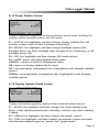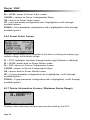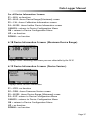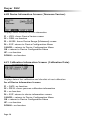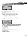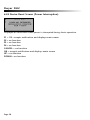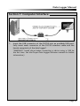
1
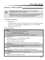
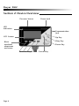
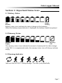
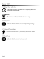
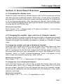
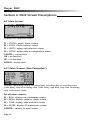
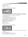
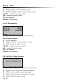
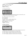
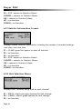
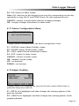
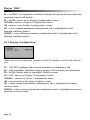
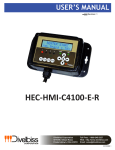
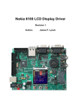
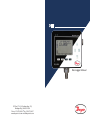
DLI2
Data Logger Manual
P.O. Box 373 l 102 Indiana Hwy. 212,
Michigan City, IN 46361 USA
Phone: 219.879.8000 l Fax: 219.872.9057
www.dwyer-inst.com l [email protected]
Table of Contents Data Logger Manual
Section 1: Device Safety............................................................................3
1.1 Model information ...................................................................3
1.2 Specifications ...........................................................................3
1.3 Warranty ..................................................................................5
Section 2: Device Overview ......................................................................6
Section 3: Status Indicator Icons ..............................................................7
3.1 Battery Status ...........................................................................7
3.2 Memory Status .........................................................................7
3.3 Running Indicator .....................................................................7
3.4 Delay Start Indicator .................................................................8
3.5 Wait Icon ..................................................................................8
3.6 Stop Icon..................................................................................8
3.7 External Power Icon ..................................................................8
3.8 Reset Icon .................................................................................8
Section 4: Front Panel Overview ..............................................................9
4.1 Changing the display units .......................................................9
4.2 Changing the number, type, and size of channels viewed.........9
4.3 Checking the memory status ..................................................10
4.4 Checking power status ...........................................................10
4.5 Changing the Contrast ...........................................................10
Section 5: DLI2 Function Reference........................................................11
5.1 Main Screen ...........................................................................11
5.2 Status Menu ...........................................................................11
5.3 Statistics Menu .......................................................................12
5.4 Units.......................................................................................13
5.5 Setup Menu ...........................................................................13
Section 6: DLI2 Screen Descriptions .......................................................18
6.1 Main Screen: ..........................................................................18
6.2 Status Screens (Run Parameters): ............................................18
6.3 Status Screens (Memory Status):.............................................19
6.4 Status Screens (Time): ............................................................19
6.5 ID Parameters .........................................................................20
6.6 Statistics Menu Screen: ...........................................................20
Revised 08/13/08
Page 1
Dwyer DLI2
6.7 Channel Statistics: ..................................................................21
6.8 Type Statistics: ........................................................................21
6.9 Statistics Information Screen: ..................................................22
6.10 Unit Selection Menu: ............................................................22
6.11 Device Configuration Menu:.................................................23
6.12 Adjust Visibility: ....................................................................23
6.13 Display Configuration: ..........................................................24
6.14 Power Modes Screen: ...........................................................25
6.15 Display Update Mode Screen:...............................................25
6.16 Power Status Screen: ............................................................26
6.17 Device Information Screens (Minimum Device Range): .........26
6.18 Device Information Screens (Maximum Device Range): ........27
6.19 Device Information Screens (Device Version): .......................27
6.20 Device Information Screens (Firmware Version): ...................28
6.21 Calibration Information Screens (Calibration Date): ..............28
6.22 Calibration Information Screens (Pressure Calibration): .........29
6.23 Device Reset Screen (Hardware Reset): .................................29
6.24 Device Reset Screen (Power Interruption): ............................30
Section 7: Computer Interface ...............................................................31
Section 9: Maintenance ..........................................................................32
Section 10: Terms and Conditions ..........................................................33
10.1 Limited Warranty: .................................................................33
10.2 Limitations:...........................................................................35
10.3 Software License: ..................................................................35
Page 2
Data Logger Manual
Section 1: Device Safety
CAUTION: DEVICE MUST BE USED ONLY IN A MANNER
CONSISTENT WITH THIS MANUAL.
NOTICE: WHEN 230VAC SUPPLY USED, DWYER SPECIFIES USE OF
AC SUPPLY PART # T35-9-100R-3 MANUFACTURED BY ENG
ELECTRIC. THIS SUPPLY IS AVAILABLE FROM DWYER.
1.1 Model information
•
Model: DLI2
•
Description: Measure and record pressure with LCD display featuring
real-time on screen graphing capabilities and a 1/4” NPT fitting.
•
Manufactured in the USA
1.2 Specifications
Pressure
Range: 0 to 30, 100, 300 and 500 psia/g
0 to 1000 and 5000 psia
Resolution: 0.002, 0.005, 0.02, 0.05 psia/g
Calibrated Accuracy: 2% FSR, 0.25% @ 77°F (25°C) typical
Dot-Matrix LCD
Dimensions: 2.5” x 1.375” (63mm x 35mm)
Text: Configurable channel text size
Indicators: Power, status, memory
Backlight: Configurable w/auto shut-off and contrast adjustment
Start/Stop Time:
Software programmable start time and date, up to six months in
advance; programmable stop time
Memory:
262,143 total readings; software configurable memory wrap
Reading Rate:
1 reading every 2 seconds to 1 every 24 hours
Calibration:
Digital calibration through software
Page 3
Dwyer DLI2
Calibration Date:
Automatically recorded within device
Battery Type:
6 alkaline AA batteries, user replaceable; optional AC adapter,
7-24 VDC, 100mA. For 230 VAC operation use AC supply
T35-9-100 R-3 made by ENG Electric.
Battery Life:
60 days typical with continuous screen use; 360 days with display off.
Data Format:
Date and time stamped PSI, inHg, mmHg, bar, atm, Torr, Pa,
kPa, MPa
Time Accuracy:
±1 minute/month at 68 to 86ºF (20 to 30°C)
Computer Interface:
PC serial or USB (interface cable required); 115,200 baud
Software:
Windows 95/98/ME/NT/2000/XP based software
Operating Environment:
68 to 140ºF (-20 to +60ºC), 0 to 95%RH non-condensing
Dimensions:
5.1” x 4.8” x 1.78” (130mm x 122mm x 45mm)
Weight:
40 oz (1134 g)
Enclosure:
Black anodized aluminum
Page 4
Data Logger Manual
1.3 Warranty
Products manufactured by Dwyer Instruments, Inc., are warranted against
defective material and workmanship for a period of one year, starting from
the date of shipment. In the event that a Dwyer product is found to be
defective, Dwyer will repair or replace the product at its sole discretion.
Such repair or replacement shall be the sole remedy of this warranty.
This warranty extends only to the original purchasing customer and does
not apply to any unit, which in our sole judgment, has been subjected to:
a)
Operating or environmental conditions in excess of our written
specifications or recommendations;
b) Damage, misuse or neglect;
c) Improper installation, repair or alteration.
This warranty excludes batteries.
Except as to title, this is our only warranty for the products. Dwyer
Instruments, Inc. expressly disclaims all other warranties, guarantees or
remedies—whether expressed or implied or statutory—including any
implied warranty of merchantability or fitness for a particular purpose. We
also disclaim any implied warranty arising out of trade usage or out of a
course dealing or course of performance. We do not guarantee the integrity of
data or warranty that the products will operate uninterrupted or error-free.
Dwyer data loggers and their associated software have been thoroughly tested
and the documentation reviewed. However, Dwyer does not warrant the
performance of its products, or that the products or their associated software will
operate as described in this manual.
Please refer to page 33 for Dwyer’s complete Terms and Conditions.
Page 5
Dwyer DLI2
Section 2: Device Overview
Pressure Sensor
Power Jack
LED
Indicators
Communication
Jack
LCD Screen
Up Key
Okay Key
Black
anodized
aluminum
enclosure
Down Key
Function Keys
Page 6
Cancel Key
Data Logger Manual
Section 3: Important Status Icons
3.1 Battery Status
Full
Battery
Empty
Battery
Battery status icons indicate the state of charge of the batteries.
When the battery empty indicator is displayed, the battery should be replaced.
3.2 Memory Status
Memory
Empty
Memory
Full
The memory status icons indicate the amount of memory left for data storage.
If the DLI2 is in wraparound mode, the memory status icon will always indicate
empty.
3.3 Running Indicator
Indicates that the DLI2 is taking readings. The icons cycle periodically.
Page 7
Dwyer DLI2
3.4 Delay Start Indicator
The delay start icon indicates that a logging operation is
scheduled for the future.
3.5 Wait Icon
The wait icon indicates that the device is busy.
3.6 Stop Icon
Indicates that the DLI2 is not currently taking readings.
3.7 External Power Icon
Indicates that the DLI2 is powered by an external source.
3.8 Reset Icon
Indicates that the device has been reset.
Page 8
Data Logger Manual
Section 4: Front Panel Overview
4.1 Changing the display units
The DLI2 comes with factory default display units of PSI for pressure and the
real-time pressure graphing feature. These units can be easily changed by
pressing the F3 button in the main screen and then selecting F1 for pressure
or F2 for the pressure graph. After selecting the channel, the available units
can be scrolled through by either pressing the channel’s function key repeatedly
or using the UP and DOWN keys.
Button pressing chain:
Main Screen -> F3 -> F1(pressure) or F2 (pressure graph) -> function key
repeatedly or UP and DOWN
4.2 Changing the number, type, and size of channels viewed
By default the DLI2 displays recently measured values of the pressure channel
and the real-time pressure graph on its Main Screen in a large size font. The
channel and graph can, however, be hidden or viewed on a smaller or larger
scale.
To change the number and type of displayed channels:
From the Main Screen, press the F4 key to enter the Setup Menu and from
this menu press the F1 key to enter the Display screen. On this screen, F1
and F2 correspond to the Pressure channel and Pressure graph respectively.
Pressing these function keys repeatedly will cause the channels to scroll
between “show” or “hide” channels displaying “show” will appear on the
main screen and channels displaying “hide” will not.
Button pressing chain:
Main Screen -> F4 -> F1 -> F1(pressure) or F2 (pressure graph)
To change the size of displayed channels:
From the Main Screen, press the F4 key to enter the Setup Menu and from
this menu press the F1 key to enter the Display screen, then F4 to scroll to
the next screen. Here the F2 key will change the size of the channels viewed.
By pressing F2 repeatedly the size parameter will scroll between 3 sizes: small,
medium, and large.
Button pressing chain:
Main Screen -> F4 -> F1 -> F4 -> F2 repeatedly to scroll
Page 9
Dwyer DLI2
4.3 Checking the memory status
A status icon appears on all screens representing memory, but further
information including percent memory left and number of readings taken
can also be viewed. From the Main Screen press the F1 key to enter the
Status screens then press F2 to view memory status information.
Button pressing chain:
Main Screen -> F1 -> F2
4.4 Checking power status
A battery status and external power status (if available) icon appear on all
screens, but percent battery power remaining and external power presence
as well as battery type, current battery voltage, and current external voltage
can also be viewed. From the Main Screen press F4 to view the Device
Configuration Menu, F2 to access the power options, then F4 twice to view
the Power Status screen, including battery power percent remaining and
the presence of external power. Battery type and battery voltage are also
displayed, as well as external power voltage (if connected).
Button pressing chain:
Main Screen -> F4 -> F2 -> F4 -> F4
4.5 Changing the contrast
The DLI2’s LCD screen contrast values can be changed in two ways. One method
is outlined in the Function Reference Guide. A faster, simpler way involves
simultaneously pressing the CANCEL and UP or DOWN button repeatedly
in any screen.
Button pressing chain:
CANCEL + UP repeatedly (to increase) or DOWN repeatedly (to decrease)
Page 10
Data Logger Manual
Section 5: DLI2 Function Reference
5.1 Main Screen
The main screen of the DLI2 features a real-time display of most recently
measured pressure data and a real-time graph of the 100 most recently
recorded data points. At the bottom of the main screen are tabs corresponding
to each of the four function keys. These tabs are used to access the four
main function menus of the DLI2: status, statistics, units, and setup. The
left side of the main screen and all subsequent screens of the device is where
important status information icons can be found (detailed in Section 3:
Important Status Icons – page 5) including recording status, memory status,
busy status, external power status, and battery power status.
5.2 Status Menu
Pressing F1 on the main screen brings up the Status menu. The first screen that
appears in the Status Menu is Run Parameters, but the Memory Status and
Time screens can also be viewed by pressing the F2 and F3 keys respectively.
5.2.i Run Parameters
The Run Parameters screen displays important information regarding the
device’s current recording session. These parameters include the time and
date the recording session started (start time and start date), the time and
date the recording session will end (stop date and stop time) due to either
a full memory or preprogramming in the Dwyer software. The rate at which
the DLI2 is recording (rate) is also displayed. The device’s current status
(either running or stopped) is the last parameter on the Run Parameters screen.
5.2.ii Memory Status
The Memory Status screen is where all information regarding the DLI2’s
memory. This screen displays the percent of memory space currently available
(memory left), the number of readings currently stored on the device (readings),
the maximum number of readings the device can record (max readings),
as well as information about the wrap feature displaying either “disabled”
or the number of wrap readings currently stored in memory.
5.2.iii Time and Date
The time and date screen displays current time data including the current
time and date, time and date of last measured data, and current time zone.
Page 11
Dwyer DLI2
5.3 Statistics Menu
Pressing the F2 key while in the Main Screen brings up the Statistics Menu.
From the Statistics Menu, statistics generated from the conditions encountered
by the device can be viewed in a variety of different styles including being
sorted by channel and by type. The Statistics Menu also displays important
statistics information as well as the option to clear the statistics at any time.
5.3.i Viewing statistics by channel
Pressing F1 while viewing the Statistics Menu brings up statistics sorted by
channel. Here the F1 key provides the ability to view statistics regarding
pressure. The screen displays the minimum, maximum, and average pressure
values encountered by the device.
5.3.ii Viewing statistics by type
The DLI2’s Statistics Menu also provides the option to view statistics by type.
This can be done by pressing F2 while in the Statistics Menu. Here the function
keys F1, F2, and F3 correspond to the three different types of statistics: average,
minimum, and maximum respectively. Each type screen displays the values
of pressure encountered by the device of the particular type.
5.3.iii Statistics Information
Pressing the F3 key while viewing the Statistics Menu screen brings up
Statistics Information. This screen displays the number of readings being
considered within the statistics (readings), as well as the date and time the
recording period began. From this screen the statistics information can also be
cleared. This is done by pressing the F1 key marked by a tab labeled “CLEAR”.
Upon pressing this key a confirmation message will appear with function tabs
labeled “NO” and “YES” corresponding to F1 and F2 respectively. Selecting
“YES” by pressing the F2 key will confirm the statistics clear function.
Page 12
Data Logger Manual
5.4 Units
Pressing the F3 key while viewing the Main Screen will access the Units Selection
screen. Here the measurement units can be easily changed. In the Units
Selection screen the F1 function key corresponds to the pressure channel and
the F2 key corresponds to the pressure graph. Selecting a channel by pressing
its corresponding function key allows the user to change the units by either
pressing the function key repeatedly or using the UP and DOWN keys to
scroll through the list of available units. Selecting OK (either by pressing the
OK button or the F4 key) accepts and confirms the unit selection. Pressing
the CANCEL key cancels the unit changing action and reverts to the previously
selected units. The DLI2 offers most commonly used units.
5.5 Setup Menu
Pressing the F4 key while in the Main Screen will display the Device
Configuration screen. From this menu changes can be made to most of the
DLI2’s display configuration including the screen contrast, size of the
channel view in the main screen, as well as display of the channels. Power
status can also be viewed including battery power remaining and the presence
of external power, and options regarding the LCD and the backlight can
be modified. The setup menu is also the place to find basic information
regarding device identification, calibration parameters, and firmware details.
5.5.i Display
From the Display section, the number and identity of channels shown on
the main screen can be changed and set, the LCD screen’s contrast values
can be changed and set, and the size the channel information appears on
the main screen can be changed and set. Pressing F1 while in the Setup
Menu brings up the Display section.
5.5.i.a Adjust Visibility
The first screen that appears in the Display section is the Adjust Visibility
screen. Here the F1 and F2 key correspond to the pressure channel and
pressure graph respectively. Pressing these function keys results in high
lighting their corresponding channel function tab. While a channel is
highlighted the corresponding display function can be toggled between
“Hide” and “Show”, with “Hide” indicating that the channel will not be
displayed on the main screen and “Show” indicating that it will be shown.
Channels can be toggled by either repeatedly pressing the channel’s
corresponding function key or by using the UP and DOWN keys.
Page 13
Dwyer DLI2
Note: Use of the DLI2’s graphing function will reduce the battery life of the
device, particularly when not logging. To increase battery life either deactivate the
graphing function by turning it to “Hide” in the Adjust Visibility screen, increase “auto
time” in the Display Update Mode screen, or change the Graph Source from ‘auto’ to
‘reading’. Alternatively, use the AC adapter for continuous power and graphing ability.
5.5.i.b Display Configuration
By selecting “MORE” (either by pressing the F4 key on the Adjust Visibility
Screen or by pressing the OK button) in the Display section the Display
Configuration screen can be viewed. Here LCD screen contrast values can
be set as well as the size the channels are displayed on the Main Screen.
Contrast
To change the LCD contrast view while viewing the Display Configuration
screen, first select the contrast configuration parameter by pressing the
F1 key. This action will highlight the function tab corresponding to
the F1 key. Once this tab is highlighted the contrast can be increased
or decreased using the UP and DOWN keys.
Size
To change the size that each channel is displayed on the Main Screen
view while viewing the Display Configuration screen, first
select the size configuration parameter by pressing the F2 key. This
action will highlight the function tab corresponding to the F2 key.
Once this tab is highlighted the size can be increased or decreased
using the UP and DOWN keys. Sizes include: small, medium, and
large
5.5.ii Power
The Power section displays information regarding battery and external power
sources as well as giving options including display and backlight status that
could potentially save power and LED status options.
5.5.ii.a Power Modes
The power modes screen displays information regarding the display,
backlight and LED mode as well as the options to change their function.
Page 14
Data Logger Manual
Display
The DLI2’s LCD has options to be either on continuously or turn off
automatically after five minutes of inactivity. This option can be
changed by first pressing the F1 key to highlight the display parameter
configuration tab. Once the tab is highlighted the option can be
changed by pressing the F1 key repeatedly or using the UP and
DOWN keys to select either “On” or “Auto”.
Backlight
Like the display, the LCD backlight also has power saving options.
The backlight can be either on, off, or set to automatically shut off after
30 seconds of inactivity. This option can be changed by first pressing
the F2 key to highlight the backlight parameter configuration tab.
Once the tab is highlighted the option can be changed by pressing
the F2 key repeatedly or using the UP and DOWN keys to select
either “On”, “Off” or “Auto”.
LED Modes
The function of the two LEDs on the upper left corner of the DLI2
can be regulated by first pressing the F3 key to highlight the LED
parameter configuration tab. Once the tab is highlighted the option
can be changed by pressing the F3 key repeatedly or using the UP
and DOWN keys to select either “Enabled” meaning the LEDs will
light to indicate device function or “Disabled” meaning the LEDs
will never light.
5.5.ii.b Display Update Mode
Selecting “MORE” by either pressing the F4 key or “OK” key while
viewing the Power Modes screen brings up the Display Update Mode
screen. On this screen, options relating to the refresh rate of the
screen are displayed. The F1 key changes the refresh rate of the
whole main screen and the F2 key changes the refresh rate of the
graphing feature. Both parameters toggle between ‘auto’ and ‘reading’.
In ‘auto’ mode, the display is updated periodically according to the
time displayed by the Auto Time parameter (which can be changed
using the F3 key), whereas in ‘reading’ mode, the display only updates
after a reading is taken.
Page 15
Dwyer DLI2
5.5.ii.c Power Status
Selecting “MORE” by either pressing the F4 key or the OK key while
viewing the Display Update Mode screen brings up the Power Status
screen. On this screen the battery type is displayed and should be
changed by the user based on whether a Lithium or Alkaline battery
is used in the DLI2. This can be changed by first pressing the F1
button to highlight the type parameter configuration tab. Once the
tab is highlighted, the battery type can be changed by either
pressing the F1 key repeatedly or by using the UP and DOWN arrows
to select the correct battery type. The percent battery power remaining,
external power presence, battery voltage and external power voltage
are also displayed on the Power Status screen.
5.5.iii Device Information
The F3 key in the Setup Menu displays the Device Information screens. Here
device identification information can be found including serial number, product
ID, revision, and subtype. Calibration parameters are also found under device
information including the date the device was last calibrated and when it will
be due for calibration again. Firmware details are also found here.
5.5.iii.a Device Range (Minimum)
The Minimum Device Range screen can be accessed by pressing the
F1 key while viewing the Device Information screen. This display
indicates the minimum values which the DLI2 is capable of detecting
and logging. Values on this screen cannot be modified.
5.5.iii.b Device Range (Maximum)
The Maximum Device Range screen can be accessed by pressing the
F2 key while viewing the Minimum Device Range screen. This display
indicates the maximum values which the DLI2 is capable of detecting
and logging. Values on this screen cannot be modified.
5.5.iii.c Calibration Parameters
Pressing F3 while in the Maximum or Minimum Device Range screens
will display the device calibration parameters. This screen displays
information indicating the most recent calibration date as well as the
date the next calibration will be due.
It is important to keep your device properly calibrated to ensure
accurate readings.
Page 16
Data Logger Manual
5.5.iii.d Device Version
Pressing the F4 key while viewing the Maximum or Minimum Device
Range screens will display the Device Version screen, containing
information such as firmware revision number and communications
baud rate. Values on this screen cannot be modified.
5.5.iii.e Firmware Version
Firmware details can be viewed by pressing the F2 key while viewing
the Device Version screens. These details include the firmware version
number, date and time of firmware creation, and checksum.
Page 17
Dwyer DLI2
Section 6: DLI2 Screen Descriptions
6.1 Main Screen:
Displays last measured values.
F1 = STATUS: enters status screens
F2 = STATS: shows statistics menu
F3 = UNITS: enters unit selection screen
F4 = SETUP: enters device configuration menu
CANCEL = no function
OK = no function
UP = no function
DOWN = no function
6.2 Status Screens (Run Parameters):
Displays information about run parameters including date of recording start
(start date), time of recording start (start time), stop date, stop time, recording
rate, and current status.
For all status screens:
F1 = RUN: displays run parameters screen
F2 = MEM: displays memory status screen
F3 = TIME: displays date and time screen
F4 = MORE: displays ID parameters screen
CANCEL = returns to main screen
Page 18
Data Logger Manual
OK = returns to main screen
UP = no function
DOWN = no function
6.3 Status Screens (Memory Status):
Displays information about the device’s memory capabilities including percent
of memory available (memory left), number of readings taken so far (readings),
max number of readings (max readings), and wrap status.
For all status screens:
F1 = RUN: displays run parameters screen
F2 = MEM: displays memory status screen
F3 = TIME: displays date and time screen
F4 = MORE: displays ID parameters screen
CANCEL = returns to main screen
OK = returns to main screen
UP = no function
DOWN = no function
6.4 Status Screens (Date and Time):
Displays current time and date as well as registered time and date and time zone
information.
For all status screens:
F1 = RUN: displays run parameters screen
F2 = MEM: displays memory status screen
Page 19
Dwyer DLI2
F3 = TIME: displays date and time screen
F4 = MORE: displays ID parameters status screen
CANCEL = returns to main screen
OK = returns to main screen
UP = no function
DOWN = no function
6.5 ID Parameters
Displays information relating to device identity.
For all status screens:
F1 = ID: no function
F3 = MORE: displays run parameters screen
F4 = EXIT: returns to main screen
CANCEL = returns to main screen
OK = returns to main screen
UP = no function
DOWN = no function
6.6 Statistics Menu Screen:
Displays options available within the statistics menu.
F1 = CHAN: shows statistics sorted by channel
F2 = TYPE: shows statistics sorted by type
F3 = INFO: enters Statistics Information Screen
F4 = EXIT: returns to main screen
Page 20
Data Logger Manual
CANCEL = returns to main screen
OK = returns to main screen
UP = no function
DOWN = no function
6.7 Channel Statistics:
Displays statistics (maximum recorded value, minimum recorded value, and
average recorded value) for the pressure channel.
F1 = PRESS: Displays pressure statistics
F2 = no function
F3 = no function
F4 = EXIT: returns to Statistics Menu Screen
CANCEL = returns to Statistics Menu
OK = returns to Statistics Menu
UP = no function
DOWN = no function
6.8 Type Statistics:
Displays statistics from from the pressure channel sorted by type (maximum
recorded value, minimum recorded value, or average value).
F1 = AVG: displays average recorded value for the channel
F2 = MIN: displays minimum recorded value for the channel
F3 = MAX: displays maximum recorded value for the channel
Page 21
Dwyer DLI2
F4 = EXIT: returns to Statistics Menu
CANCEL = returns to Statistics Menu
OK = returns to Statistics Menu
UP = no function
DOWN = no function
6.9 Statistics Information Screen:
Displays current statistics information including the number of recorded readings,
start date, and start time.
F1 = CLEAR: gives the option to clear all statistics
F2 = no function
F3 = no function
F4 = EXIT: returns to Statistics Menu
CANCEL = returns to Statistics Menu
OK = returns to Statistics Menu
UP = no function
DOWN = no function
6.10 Unit Selection Menu:
Displays units currently being used for each channel
F1 = PRESS: selects pressure channel for unit change
F2 = GRAPH: selects graph feature for unit change
F3 = no function
Page 22
Data Logger Manual
F4 = OK: returns to Main Screen
Note: Unit selection can be changed by pressing the corresponding function key
repeatedly or using the UP and DOWN arrows to select appropriate units.
CANCEL = returns to main menu without accepting changes
OK = accepts changes and returns to main menu
6.11 Device Configuration Menu:
Displays options available within the device configuration menu.
F1 = DISPLAY: enters Adjust Visibility screen
F2 = POWER: enters Power Modes screen
F3 = INFO: enters Device Information screens
F4 = EXIT: returns to main screen
CANCEL = returns to main screen
OK = returns to main screen
UP = no function
DOWN = no function
6.12 Adjust Visibility:
Displays options for changing the view on the main screen (either shows a
particular channel or hides it).
F1 = PRESS: first highlights and then changes the viewing options of the
pressure channel
F2 = GRAPH: first highlights and then changes the viewing options of the
graphing feature
Page 23
Dwyer DLI2
F3 = SOURCE: first highlights and then changes the option for how often the
graphing feature will update
F4 = MORE: moves on to Display Configuration screen
CANCEL= return to Display Configuration Menu
OK = moves on to Display Configuration screen
UP = once channel parameter configuration tab is highlighted scrolls
through available options
DOWN = once channel parameter configuration tab is highlighted scrolls
through available options
6.13 Display Configuration:
Allows the user to change the contrast of the LCD display as well as the channel
size.
F1 = CNTRST: highlights the contrast parameter configuration tab
F2 = SIZE: highlights and then changes options of the channel size parameter
F3 = MORE: moves back to the Adjust Visibility screen
F4 = EXIT: returns to Display Configuration Menu
CANCEL = returns to Device Configuration Menu
OK = moves back to the Adjust Visibility screen
UP = when contrast parameter configuration tab is highlighted increases
contrast value
DOWN = when contrast parameter configuration tab is highlighted increases
decreases contrast value
Page 24
Data Logger Manual
6.14 Power Modes Screen:
Displays information regarding the devices different power modes including the
display visibility, backlight options, and LED modes.
F1 = DISPLAY: first highlights and then changes display visibility (On: full
visibility or Auto: shuts off after 5 minutes of inactivity)
F2 = BKLGHT: first highlights and then changes backlight options (On:
backlight always on, Auto: backlight shuts off after 30 sec of inactivity, or Off:
backlight always off)
F3 = LED: first highlights and then changes LED mode options
F4 = MORE: moves to Display Update Mode screen
CANCEL = returns to Device Configuration Menu
OK = moves to Display Update Mode screen
UP = once parameter configuration tab is highlighted scrolls through available
options
DOWN = once parameter configuration tab is highlighted scrolls through
available options
6.15 Display Update Mode Screen:
Displays information regarding display refresh mode and refresh interval.
F1 = MODE: first highlights and then changes the screen update mode
(Auto: screen refreshes periodically or Reading: refreshes only after a reading
is taken)
F2 = GRAPH: first highlights and then changes the graph’s source.
F3 = TIME: first highlights and then changes the amount of time associated
with the Auto referesh option in “mode” and “graph mode”.
Page 25
Dwyer DLI2
F4 = MORE: moves to Power Status screen
CANCEL = returns to Device Configuration Menu
OK = moves to Power Status screen
UP = once parameter configuration tab is highlighted scrolls through
available options
DOWN = once parameter configuration tab is highlighted scrolls through
available options
6.16 Power Status Screen:
Displays details about power available to the device including the battery type,
battery voltage, and external voltage.
F1 = TYPE: highlights and then changes battery type (Lithium or Alkaline)
F3 = MORE: moves back to Power Modes screen
F4 = EXIT: returns to Device Configuration Screen
CANCEL: returns to Device Configuration Menu
OK = moves back to Power Modes screen
UP = if type parameter configuration tab is highlighted, scrolls through
available options
DOWN = if type parameter configuration tab is highlighted, scrolls through
available options
6.17 Device Information Screens (Minimum Device Range):
Displays values indicating minimum pressure detectable by the DLI2.
Page 26
Data Logger Manual
For all Device Information Screens:
F1 = MIN: no function
F2 = MAX: shows Device Range (Maximum) screen
F3 = CAL: shows Calibration Information screens
F4 = MORE: shows further Device Information screens
CANCEL = returns to Device Configuration Menu
OK = returns to Device Configuration Menu
UP = no function
DOWN = no function
6.18 Device Information Screens (Maximum Device Range):
Displays values indicating maximum pressure detectable by the DLI2.
6.19 Device Information Screens (Device Version):
Displays device version information.
F1 = VERS: no function
F2 = FIRM: shows Firmware Version screen
F3 = MORE: shows Device Range (Minimum) screen
F4 = EXIT: returns to Device Configuration Menu
CANCEL = returns to Device Configuration Menu
OK = returns to Device Configuration Menu
UP = no function
DOWN = no function
Page 27
Dwyer DLI2
6.20 Device Information Screens (Firmware Version):
Displays device firmware version information.
F1 = VERS: shows Device Version screen
F2 = FIRM: no function
F3 = MORE: shows Device Range (Minimum) screen
F4 = EXIT: returns to Device Configuration Menu
CANCEL = returns to Device Configuration Menu
OK = returns to Device Configuration Menu
UP = no function
DOWN = no function
6.21 Calibration Information Screens (Calibration Date):
Displays date of last calibration and due date of next calibration.
For all Device Information Screens:
F1 = DATE: no function
F2 = PRESS: shows pressure calibration information
F3 = no function
F4 = EXIT: returns to device information screens
CANCEL = returns to Device Configuration Menu
OK = returns to Device Configuration Menu
UP = no function
DOWN = no function
Page 28
Data Logger Manual
6.22 Calibration Information Screens (Pressure Calibration):
Displays calibration information for pressure channel.
For all Device Information Screens:
F1 = DATE: returns to Calibration Date screen
F2 = PRESS: no fucntion
F4 = EXIT: returns to Device Information screens
CANCEL = returns to Device Information screens
OK = returns to Device Information screens
UP = no function
DOWN = no function
6.23 Device Reset Screen (Hardware Reset):
Displayed as notification when a hardware reset has occurred.
F1 = OK: accepts notification and displays main screen
F2 = no function
F3 = no function
F4 = no function
CANCEL = no function
OK = accepts notification and displays main screen
UP = no function
DOWN = no function
Page 29
Dwyer DLI2
6.24 Device Reset Screen (Power Interruption):
Displayed as notification when power is interrupted during device operation.
F1 = OK: accepts notification and displays main screen
F2 = no function
F3 = no function
F4 = no function
CANCEL = no function
OK = accepts notification and displays main screen
UP = no function
DOWN = no function
Page 30
Data Logger Manual
Section 7: Computer Interface:
1.
Insert the USB connector of the DL700 into an available USB port.
Fully insert male connector of the DL700 interface cable into the
female receptacle of the data logger*.
*WARNING: Install driver before connecting a device using a USB for
the first time. See the Dwyer Data Logger Software manual for further
information.)
Page 31
Dwyer DLI2
Section 9: Maintenance
BATTERY WARNING
Many Dwyer data loggers contain a lithium battery. Do
not cut the battery open, incinerate, or recharge. Do not heat
lithium batteries above the specified operating temperature.*
Dispose of the battery in accordance with local regulations.
*See the individual specification sheets at www.Dwyer-inst.com.
The DLI2 does not have any user-serviceable parts except the battery which
should be replaced periodically. The battery life is affected by battery type,
ambient temperature, sample rate, sensor selection, offloads and LCD
display usage. The DLI2 has a battery status indicator on the LCD display.
If the battery indication is low, or if the device seems to be inoperable, it is
recommended that the battery be changed.
To change the batteries, locate and remove the four(4) 9/64” hex screws on
the back of the unit. Separate the halves and the battery compartment is now
visible. Remove the old AA batteries from the battery holder and replace with
six(6) new AA alkaline batteries as indicated on the holder. When replacing
the cover, make sure that the gasket is still seated in its groove, and that all
wires are tucked away inside the compartment.
For any other maintenance or calibration issues, Dwyer recommends the
unit be returned to the factory for service. Before returning the device, you
must obtain an RGA from the factory. For further information, please contact
Dwyer at:
Dwyer Instruments, Inc.
P.O. Box 373, 102 Indiana Hwy. 212
Michigan City, IN 46361 USA
TEL: (219) 879-8000 • FAX: (219) 872-9057
www.dwyer-inst.com
[email protected]
Page 32
Data Logger Manual
Section 10: Terms and Conditions
All products furnished by Dwyer, Inc. (“Seller”) shall be in accordance with the
following terms and conditions unless otherwise stated in writing:
These Terms and Conditions (“Terms and Conditions”) govern (a) all sales
quotations and sales of components, equipment, parts, and other products (“Product”)
from, and (b) all service proposals and provisions of services by Seller to the buyer of
the Products (“Buyer”). These Terms and Conditions shall take precedence over any
terms and conditions which appear on Buyer’s order or other form or any other writing
or electronic transmission from Buyer. Any terms or conditions on any of Buyer’s forms,
recordings, electronic transmissions, or orders that are different from or in addition
to these Terms and Conditions are specifically rejected. Any modification to these
Terms and Conditions must be agreed to and executed in writing by Seller. Seller’s
failure to object to provisions contained in any communication from Buyer shall not be
construed as a waiver of these Terms and Conditions or as an acceptance of any such
provision. Trade custom, trade usage and past performance are superseded by these
terms and conditions and shall not be used to interpret these terms and conditions.
In the event that Product includes software, the software is licensed to Buyer in object
code form only in accordance with Seller’s standard Software License Terms that are
included below.
10.1 Limited Warranty.
A. Seller Manufactured Products and Seller Provided Services.
Seller warrants to Buyer that:
(i) Seller manufactured Software (as defined in Section 23 below) shall execute the
programming instructions provided by Seller, and
(ii) Seller manufactured Product and consumables and Seller provided services shall
be free from material defects in material and workmanship under normal uses
and care, in each case until the expiration of the applicable warranty period
specified below
Seller manufactured Product is warranted for the shorter of twelve (12) months
from the date of initial installation or fifteen (15) months from the date of shipment by
Seller. Seller manufactured consumables and Software, and Seller provided services are
warranted for a period of ninety (90) days from the date of shipment or completion, as
applicable. If Buyer discovers any warranty defect and notifies Seller thereof in writing
during the applicable warranty period, Seller shall, at its option, promptly correct any
Page 33
Dwyer DLI2
defects that are found by Seller, or repair or replace F.O.B. point of manufacture that
portion of the Seller manufactured Products, consumables or Software found by Seller
to be defective, or refund the price of the defective portion of the Seller manufactured
Products, consumables or Software, or of the defective portion of the Seller provided
services. All replacements or repairs necessitated by inadequate maintenance, normal wear and usage, unsuitable power sources, unsuitable environmental conditions,
accident, misuse, improper installation, modification, repair, storage or handling, or
any other cause not the fault of Seller are not covered by this limited warranty, and
shall be at Buyer’s expense. Seller shall not be obligated to pay any costs or charges
incurred by Buyer or any other party except as may be agreed upon in writing in
advance by an authorized representative of Seller. All costs of dismantling,
re-installation and freight, and the time and expenses of Seller’s personnel for site travel
and diagnosis under this limited warranty shall be borne by Buyer unless accepted
in writing by Seller. Seller manufactured Products, consumables and Software, and
Seller provided services, repaired, replaced or corrected during the applicable warranty
period shall be in warranty for the greater of the remainder of the applicable original
warranty period or ninety (90) days.
THE FOREGOING STATES THE SOLE AND EXCLUSIVE WARRANTY AND LIABILITY
OF SELLER. FOR BREACH OF WARRANTY AND IS IN LIEU OF ALL OTHER
REPRESENTATIONS, WARRANTIES AND COVENANTS, EXPRESSED OR IMPLIED, IN
REGARD THERETO. EXCEPT FOR THE EXPRESS LIMITED WARRANTY SET FORTH IN
THIS SECTION, SELLER DOES NOT MAKE AND HEREBY DISCLAIMS ANY AND ALL
OTHER REPRESENTATIONS AND WARRANTIES OF ANY KIND WHATSOEVER, WHETHER
EXPRESSED, IMPLIED OR STATUTORY, INCLUDING, WITHOUT LIMITATION, ANY
IMPLIED WARRANTIES OF MERCHANTABILITY, FITNESS FOR A PARTICULAR PURPOSE,
NONINFRINGEMENT OR ACCURACY, ADEQUACY OR COMPLETENESS OF DATA
MEASUREMENT, WITH RESPECT TO ANY OF THE SELLER MANUFACTURED PRODUCTS,
CONSUMABLES OR SOFTWARE, OR ANY OF THE SELLER PROVIDED SERVICES.
Any drawings submitted with the Products are only to show the general style,
arrangement, and approximate dimensions of the Products.
B. Equipment, Consumables, Software and Services Manufactured or Provided by
Others.
SELLER DOES NOT MAKE, AND HEREBY DISCLAIMS, ANY AND ALL
REPRESENTATIONS AND WARRANTIES OF ANY KIND WHATSOEVER, WHETHER
EXPRESSED, IMPLIED OR STATUTORY, INCLUDING, WITHOUT LIMITATION, ANY
IMPLIED WARRANTIES OF MERCHANTABILITY PARTICULAR PURPOSE, NONINFRINGEMENT
Page 34
Data Logger Manual
OR ACCURACY, ADEQUACY OR COMPLETENESS OF DATA MEASUREMENT, WITH
RESPECT TO ANY EQUIPMENT, COMPONENTS, PARTS, CONSUMABLES, SOFTWARE
OR SERVICES SOLD TO BUYER BY SELLER THAT ARE NOT MANUFACTURED OR
PROVIDED BY SELLER. Seller shall assign the manufacturer’s or service provider’s
warranty applicable to such equipment, components, parts, consumables, Software
and services to the extent permitted, to Buyer. Seller will provide Buyer with available
warranty information.
10.2 Limitations.
IN NO EVENT, REGARDLESS OF THE FORM OF THE CLAIM OR CAUSE OF ACTION
(WHETHER BASED IN CONTRACT, INFRINGEMENT, NEGLIGENCE, STRICT LIABILITY,
OTHER TORT OR OTHERWISE), SHALL SELLER’S LIABILITY EXCEED THE PRICE ACTUALLY
PAID BY BUYER TO SELLER FOR THE SPECIFIC PRODUCTS, CONSUMABLES AND/OR
SOFTWARE MANUFACTURED, AND/OR SERVICES PROVIDED, BY SELLER GIVING
RISE TO THE CLAIM OR CAUSE OF ACTION. SELLER SHALL NOT, UNDER ANY
CIRCUMSTANCES, BE LIABLE FOR ANY LOSS OF REVENUE, LOSS OF PROFITS OR
ANY INCIDENTAL, INDIRECT, SPECIAL, EXEMPLARY OR CONSEQUENTIAL DAMAGES,
WHETHER OR NOT FORESEEABLE. NO ACTION, REGARDLESS OF FORM, ARISING
OUT OF ANY TRANSACTION GOVERNED BY THESE TERMS AND CONDITIONS, MAY
BE BROUGHT BY EITHER PARTY MORE THAN TWO (2) YEARS AFTER THE CAUSE OF
ACTION HAS ACCRUED. The foregoing allocation of risk and limitation of liability has
been agreed to by the parties and forms the basis of their willingness to enter into any
accepted order.
10.3 Software License.
(A) For purposes hereof, “Software” means the computer programs included in
the Product at delivery, together with all codes, techniques, software tools, formats,
designs, concepts, methods, and ideas associated with those computer programs. The
term also includes all copies of any part of the software, as well as the manual(s) and
printed materials provided by Seller.
(B) Seller grants Buyer a non- exclusive, non-transferable license to use the Software, in object code form only, according to the terms set forth below. Buyer may
operate the Software only (i) in conjunction with and as part of the Product; (ii) in the
manner in which it is intended by Seller; and (iii) at Buyer’s plant site where the Product
is first used. Buyer may negotiate with Seller separate licenses to use the Software at
other plant sites. Buyer’s use of Software shall be governed exclusively by Seller’s and/
or an third party owner’s applicable license terms.
(C) Buyer shall not (i) make the Software available to any person or entity other
than its employees, who must use the Software only as specified above; (ii) modify
Page 35
Dwyer DLI2
the Software or merge it with another program; (iii) reverse engineer, disassemble,
decompile, or make any attempt to discover the source code of the Software; (iv)
translate or create derivative works based on the Software; (v) remove, obscure, or alter
any notice of the patent, copyright, or other proprietary rights related to the Software;
(vi) sub-license, sell, lend, rent, or lease any portion of the Software; (vii) copy any
portion of the Software; (viii) operate the Software other than in conjunction with
operation of Product; or (ix) transfer the Software in violation of applicable United
States Export laws and regulations.
Page 36
DLI2
Data Logger Manual
P.O. Box 373 l 102 Indiana Hwy. 212,
Michigan City, IN 46361 USA
Phone: 219.879.8000 l Fax: 219.872.9057
www.dwyer-inst.com l [email protected]