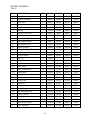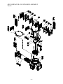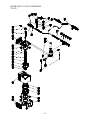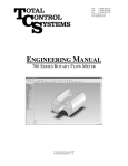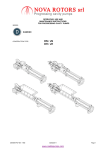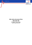
1
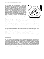
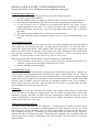
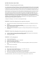
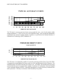
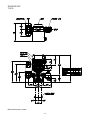
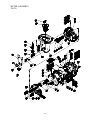
700-20 Rotary Flow Meter
SERVICE MANUAL*
* For 700 meters with serial numbers 700000 or higher
TOTAL CONTROL SYSTEMS
2515 Charleston Place • Fort Wayne, IN 46808
Toll Free: (800) 348-4753 • Tel: (260) 484-0382 • Fax: (260) 484-9230
E-mail: [email protected] • Website: www.tcsmeters.com
SPECIFICATIONS FOR MODEL 700-20
Flange Connection:
2” NPT Flange Connection, 1-1/2” NPT Flange Optional
BSPT, Slip Weld or ANSI flanges available upon request.
Flow Rate:
Up to 100 GPM (380 LPM);
Maximum Pressure:
150 PSI (10.5 BAR)
Working Temperature:
-20°F to 160°F (-28.9°C to 71°C);
METER TYPES
SP
Standard Petroleum
Refined products: Gasoline, Fuel Oil, Aviation Fuels, Kerosene,
Lubricating Oils, Vegetable Oils, etc.
IP
Industrial Products
Refined products, Solvents and Industrial Chemicals
AF All Ferrous
Refined products, Solvents, Industrial Chemicals and Agricultural
Products
SS
Refined products, Solvents, Industrial Chemicals, Agricultural
Products and Special Handling Liquids (such as some acids)
Stainless Steel
MATERIAL OF CONSTRUCTION
Type
Journals
Bearings
Bearing
Plates
Timing
Gears
Seals
Hardchrome SS
SS Alloy
316 SS
316 SS
Viton®
Hardchrome SS
SS Alloy*
316 SS
316 SS
Kalrez® &
Teflon®
316 SS
Hardchrome SS
SS Alloy*
316 SS
316 SS
316 SS
Hardchrome SS
SS Alloy*
316 SS
316 SS
Housing
Rotors
Anodized
Aluminum
Hardcoat
Anodized
Aluminum
Anodized
Aluminum
Hardcoat
Anodized
Aluminum
AF
Cast Iron
SS
316 SS
SP
IP
* Ceramic Bearings are available upon request.
Viton® is a registered trademark of E.I. Dupont de Nemours & Co.
Teflon® and Kalrez® are registered trademarks of Dupont Dow Elastomers, L.L.C.
-1-
Kalrez® &
Teflon®
Kalrez® &
Teflon®
700 ROTARY METER OPERATION
The TCS Model 700 series flow meter is a simple and
efficient design. The meter consists of a single fluid chamber
that contains a single blocking rotor and two displacement
rotors whose rotation is synchronized with mating gears. As
the fluid enters the fluid chamber, the blocking rotor is forced
to rotate.
The displacement rotors, also rotating in
conjunction with the blocking rotor help direct the fluid flow
through the chamber and to the outlet. The linear flow of the
fluid is thus translated into rotary motion in the meter. The
output of the meter is picked up from the rotation of the
blocking rotor and transmitted to a register or pulse
transmitter.
The rotors in the meter are designed to operate at close tolerances to one another and the wall of
the fluid chamber. There are slight gaps between the rotors and the chamber wall. Because of
this, it is important that the meter be properly applied for the flow rate and operating pressure of
the system.
Because the fluid flow through the meter is redirected only slightly from its natural flow, there is
very little pressure drop across the meter, unlike other meters that use multiple measuring
chambers.
The meter design uses high quality long life materials for the rotor bearings and journals. Since
there is no contact between the rotors and the fluid chamber wall, these critical components have
a long life expectancy.
Calibration of the meter involves adjusting the rotation of the output shaft relative to the rotation
of the internal rotors of the meter. This is accomplished by changing the settings on an adjuster
device. Calibration of the meter is discussed in detail in the section Meter Calibration on page 5.
ACCURACY
The TCS model 700 series flow meter holds the National Type Evaluation Program (NTEP)
Certificate of Conformance meeting the National Institute of Standards and Technology (NIST)
Handbook 44 requirements. The TCS model 700 series flow meter combines outstanding
accuracy with superior performance. At constant flow, with all other conditions being constant,
the flow meter does not vary more than +/- 0.02% in repeatability. Due to the smooth flowing
characteristics of this meter design, the minimum seal area provides a sustained accuracy over a
wide range of flow and accuracy regardless of pressure.
-2-
METER APPLICATION
When installing a meter into a system, several factors must be considered.
Flow Rate
The flow rate of the system must be within the meter's capability. The 700-20 meter can operate
up to 100 GPM (380 LPM). The flow rate of the system is dependent upon the system's pump
capabilities, and the plumbing configuration, and the product to be measured. Higher flow rates
can be achieved with products that have low viscosities and high lubricity (i.e. gasoline, diesel
fuel, aviation fuels).
Operating Pressure
The 700-20 meter can operate at pressures up to 150 PSI (10.5 BAR).
Compatibility
Products with suspended solids in them will score the meter body and rotors due to the tight
clearances within the meter’s measuring chamber. The liquid to be metered must also be
compatible with the meter. Contact factory on receiving the Chemical Compatibility Chart for
more information. Note TCS recommends that the 700-20 meter should have limited use on
water applications. Water has no lubricity and will drastically shorten the meter's service life.
It is recommended that if the meter is to be used on water, it should be derated about 40 to 50
percent of flow and NOT on continuous duty applications.
Operating Temperature
The temperature range of the product to be metered must be within the meter's range. The 70020 meter can operate between -20°F and 160°F (-20°F to 160°F (-28.9°C to 71°C). Higher
working temperatures can be achieved at reduced pressures (Consult factory for more
information).
Registration
The 700-20 meter uses a Veeder Root mechanical 5-wheel resetable register in 1/10th U.S.
gallons, with an 8-digit non-resetable totalizer. Litres, ounces, pounds or nearly any other unit of
measure can be accommodated upon request. Other electronic registers are available upon
request.
Weights & Measures Approved Device
Some liquids may require a measuring devise to have a “Type Approval” from the National
Institute of Standards and Technology (NIST) Office of Weights & Measures subsidiary
National Type Evaluation Program (NTEP) Handbook 44 requirements. This “Type Approval”
declares that the device has been performance tested and certified on specific liquid product class
within various system factors by NIST and is thereby qualified to sell a liquid product off the
measuring device. The Total Control Systems 700 series flow meter currently has a NTEP
number (99-097) for the resale of Refined Products, which include the likes of Gasoline, Diesel
Fuel, Aviation Fuels, Lube Oils, Kerosene, Mineral Spirits, Motor Oils, Vegetable Oils, etc.
-3-
INSTALLATION & START-UP RECOMMENDATIONS
Start-up instruction for new installations or after maintenance and repairs:
Best Plumbing Configuration
•
•
•
•
•
•
•
System should be designed to keep the flow meter full of liquid at all times.
Use full 2” pipe for the installation.
The pipe should be laid out as straight as possible to reduce pressure loss from flow restriction.
Meter inlet and outlet should be lower than the associated system plumbing (sump position).
It is not necessary for the air eliminator to be installed bolted directly to the meter. It can be
installed upstream from the meter. For effective operation of the air eliminator, it should be
mounted between the meter and any valves, tees or any other potential places where air may enter
the system.
The metering system should include a means to prove meter accuracy.
The meter and piping must be installed in such as way as to avoid accidental draining of the
meter.
Slow Flooding Of System
When a pump is turned on and a valve opened in a new, dry system, tremendous pressure can be built up
in the piping and forced through the meter. The high pressure and volume of air causes the meter to
operate more quickly than normal. When product reaches the meter, there is an abrupt slowing of the
meter rotors, which could cause damage to the register, rotor shafts, packing gear and/or blade, timing
gears and other components. The recommended method of starting any system is to flood the piping
gradually. This allows product to slowly force the air from the entire system.
When operating the meter with accessories, observe the following recommendations:
• Valves should be opened slowly to avoid a pressure surge that can damage the meter or air
eliminator. System pressures should be maintained below 70 PSI.
• Strainers should be cleaned frequently.
Protection From Debris
On new installations, care must be taken to protect the meter from damage during start-up. Damage may
result from the passage through the meter of welding slag or spatter, thread cuttings, rust, etc. There are
several methods of protecting meters from this material including: the insertion of a spool (a flanged
length of pipe equal in length to the meter and any accessories attached to the meter) in place of the meter
until the system is flushed, temporarily bypassing the plumbing around the meter, or by installing a
strainer ahead of the meter in the line. Once the system has run “clean” for a period of time, the meter
may be reinstalled or protective devices removed.
Calibration
The meter shall be tested and calibrated when installed. Total Control Systems shall not be responsible
for loss of product or any damages resulting from the end user’s failure to test this meter to insure proper
calibration. Improper calibration can result in incorrect measurements of fluid being delivered. It is the
owner’s responsibility to report this device to the local U.S. Weights and Measures officials for their
inspection before the meter is put to use.
Changing the Direction of Flow:
The meter is set up at the factory for left to right flow. To change the meter to right to left flow, begin by
removing the screws (#9 on the Meter Assembly Breakdown) and the adjuster cover plate (#7) on the
front of the meter. Remove both the screws (#1), the drive shaft retainer (#10), the drive shaft (#3), the ering (#4) and the face gear (#5). Reinstall the gear on the shaft with the gear teeth facing up. Snap the ering back into place to hold the gear in place. Reinstall the shaft, mating the face gear with the drive gear
of the packing capsule assembly. Reinstall the screw and cover plate. The meter will now be set up for
right to left flow.
-4-
STORAGE INSTRUCTIONS
Short periods of non-use of the meter (a week or less) will present no problem, provided that the meter remains full
of product. For long periods of non-use, such as winter storage, the following procedure is recommended. Before
long term storage, a good practice is calibration of the meter to determine that it is functioning properly.
1) To store the meter when it is left in line, flush the system with clean water until 40-50 gallons of water have
gone through the meter.
2) Pump a 50% anti-freeze / 50% water solution through the entire system (100% RV antifreeze may be used
instead). With the pump running, shut off a valve downstream from the meter, making sure that anti-freeze
solution is present at that point. Then close an upstream valve, such that the meter remains full of antifreeze solution.
3) Remove the register from the meter, and lubricate the drive coupling shaft. After lubrication it, replace the
register onto the meter.
4) When starting the system after a period of storage, rechecking the meter's calibration as detailed earlier in
the service manual.
METER CALIBRATION
The procedure to change the calibration of the meter:
1)
Check for repeatability
A) Run a fast (high gallons per minute) test in your prover and record how much the meter is over or
under registering. Do NOT change the meter's calibration.
B) Run a slow (low gallons per minute) test and again record how much the meter is over or under
registration.
If the results from the fast and the slow test are the same or close to the same, the meter can be successfully
calibrated. If the test results differ beyond the rated tolerance of the meter, then repairs are necessary
before the meter can be calibrated.
2)
3)
4)
5)
6)
7)
8)
9)
10)
11)
12)
13)
14)
15)
16)
17)
A valve or nozzle must be at the end of the delivery hose (at the prover).
Turn on the pump and purge the system of air. Leave the pump on.
Shut off the valve at the end of the delivery hose and let the system pressurize.
Wet the prover and empty it, letting it drip for 30 seconds.
Reset the register on the meter to "0".
Fill the prover to the line marked "0".
Calculate the percentage increase or decrease of registration required. For example, if a 50 gallon test
prover indicates exactly 50 gallons have been run through the meter against a meter registration of 49.7
gallons, the percentage increase of registration would be 0.6%. (3/10’s in 50 gallons is 0.6%). If meter
registration is less than the test prover measured volume, an increase adjustment is required. If meter
registration is greater than the test prover measured volume, a decrease adjustment is required.
Remove the seal and seal wire.
Remove the front cover plate.
Loosen the screw on the clamping ring. The adjuster barrel will now be free to rotate.
Each small hash mark corresponds to 0.02% adjustment. Each of the larger numbers on the rotating barrel
corresponds to 0.1%. The large numbers engraved into the adjuster body correspond to 1%. The entire
range of adjustment is 5%, with the meter being set at the factory very close to the middle of this range.
To increase the registered volume, rotate the adjuster barrel to the left by the percentage increase desired.
It is recommended that the barrel be rotated 0.02% more than the desired amount and then backed down to
the desired figure. This accounts for any slack present in the adjuster mechanism. In the example above,
the barrel would be rotated 16 tick marks on the barrel (15 tick marks x 0.02 =0.3 = 3/10’s plus the one tick
mark for slack). With the slack removed, the barrel would then be rotated one tick mark back to the right to
achieve the final adjustment.
To decrease the registered volume, the adjuster barrel is rotated to the right.
Tighten the screw and clamping ring.
Run another test and adjust if necessary.
When calibration is achieved, ensure that the screw and clamping ring are tight, then replace the cover
plate.
-5-
METER TROUBLE SHOOTING
PROBLEM: Leaking packing gland and/or housing
Two common causes of packing gland leakage are thermal expansion and hydraulic shock. If two valves in a piping
system (on either side of the meter) are closed at one time, and if the temperature rises as little as 1ºF in the system,
it could result in a rise in pressure within the system that would exceed the working pressure rating of the meter. To
avoid this hazard caused by thermal expansion, a pressure-relief valve of some kind must be installed in the system.
Hydraulic shock occurs when a large volume (mass) of liquid is moving through a pipe line at some flow rate and a
valve is suddenly closed. When the flow is so stopped, the entire mass of the liquid in the piping system acts as a
battering ram, causing a shock effect within the meter. The greater the mass, length of line and/or velocity, the
greater the hydraulic shock. Since the valve is usually located at the meter outlet, the meter housing, packing gland
and the meter internal members receive the full impact of such hydraulic shock. To prevent this hazard a slow
closing two-stage valve should be used with the meter. On those systems where mass, length of line, etc. are of such
magnitude as to preclude the elimination of hydraulic shock with the use of a two -stage slow closing valve an
impact-absorbing air cushioning device should be used.
O-Ring has been damaged or cover bolts have not been tightened enough.
PROBLEM: Product flows through meter but register does not operate.
A)
B)
C)
D)
Gear train motion interrupted by non-functioning gear due to broken pin or key. Replace pin or key where
required.
If all meter parts are moving then problem is in register.
Remove register from meter. If all meter parts are moving but output shaft of adjuster assembly is not,
adjuster is worn and must be replaced.
If totalizer numerals (small numbers) on register are recording, but the big numerals are not moving, register
needs repair.
PROBLEM: Product flows through meter but register does not record correctly.
A)
B)
C)
Adjuster assembly not properly calibrated, See METER CALIBRATION on page 5 for more instructions.
The factory installed gear train may have incorrect gearing ratio.
Check register for defects.
PROBLEM: No flow through meter.
A)
B)
C)
D)
E)
F)
Faulty non-functioning pump.
Foreign matter within the system, meter or components.
Meter has a broken rotor or rotor shaft.
Excessive wear on timing gears or bearings.
Meter “frozen” due to build-up of chemical “salts” inside metering chamber, sufficient to stop rotation or
rotors.
Valve not open or not functioning.
PROBLEM: Meter runs too slow.
A)
B)
C)
D)
E)
There is a flow restriction within the system. (i.e.: tees, elbows, valves, etc.)
Foreign matter in system, meter or components.
Product viscosity is different or has changed from what was originally known.
Meter gears or rotors partially “salted” enough to slow up rotation of parts.
Valve internal mechanism faulty. Valve does not open fully or the linkage is not properly adjusted.
For additional assistance, contact Total Control Systems Service Department at 1-800-348-4753.
-6-
KEY FEATURES OF 700 METER
% DEVIATION
TYPICAL ACCURACY CURVE
0.3
0.2
0.1
0
-0.1
-0.2
-0.3
Gasoline
Fuel Oil
0
10
20
30
40
50
60
70
80
90 100
PERCENT OF FLOW RATE
The 700 meter’s accuracy (percent of error over or under the zero – error level) remains within
design parameters (+/- 0.2%) over its 10 to 100 GPM flow range. This exceeds the maintenance
requirements for accurate custody transfer of product, as specified in the National Institute of
Standards and Technology (NIST) Handbook 44.
PRESSURE DROP CURVE
P.S.I.
32 SSU SOLVENT
3
2.5
2
1.5
1
0.5
0
0
10
20
30
40
50
60
70
80
90
100
PERCENT OF FLOW RATE
The 700 meter is mechanically capable of accurately metering products from 10 to 100 GPM.
Comparing lowest and highest flow rates results in a 10:1 turn down ratio for the 700 meter. The
nameplate on the 700 meter states the flow range as 20 – 100 GPM. This matches the flow range
across which the meter was tested while earning a Certificate of Conformance from the National
Type Evaluation Program (NTEP). It should be noted that as viscosity increases, maximum flow
rate my decrease. Viscosity is a measure of the flowability of a product.
-7-
DIMENSIONS
700-20
Measurements are in Inches.
-8-
METER ASSEMBLY
700-20
-9-
METER ASSEMBLY
700-20
ITEM # DESCRIPTION
QTY 700-20SP
700-20IP
700-20AF 700-20SS
1
2
Screw, Round Head
Adjuster Assembly
6
1
1-128279
700100
1-128279
700100
1-128279
700100
1-128279
700100
3
4
Drive Shaft
E-Ring
1
1
700019
700016
700019
700016
700019
700016
700019
700016
5
6
Face Gear
Bushing
1
2
700018
700020
7
8
Adjuster Cover Plate
Seal Wire
1
1
700017
1-118849
700018
700020
700017
700018
700020
700017
700018
700020
700017
9
10
Screw, Drilled Head
Drive Shaft Retainer
2
1
700042
700022
1-118849
700042
1-118849
700042
1-118849
700042
11
12
Head Mount Screw
Register Support
4
1
700040
700200
700022
700040
700022
700040
700022
700040
13
14
Packing Retaining Plate
Packing Capsule Assembly, 2:1
1
1
700015
700150
700200
700015
700155
700200
700015
700155
700200
700015
700155
15
16
O-ring, Packing
Plug, 3/8”
1
2
700009
700024
700010
700024
700010
700024
700010
700024
17
18
Cover, Front
Cap Screw
1
20
702500
702016
702500
702016
702501
702016
702502
702016
19
20
Cover, Rear
Screw, Round Head
1
10
702550
702014
702550
702014
702551
702014
702552
702014
21
22
Bearing Plate
O-ring, Cover
2
2
702205
702001
702215
702002
702215
702002
702215
702002
23
24
Housing
Washer, Flat
1
8
702110
702018
702115
702018
702120
702018
702125
702018
25
26
Cap Screw
Flange
8
2
702017
702600
702017
702600
27
28
O-ring, Flange
Gear, Blocking Rotor
2
1
702012
702350
702017
702602
702013
29
30
Rotor Lock Nut
Gear, Displacement Rotor
3
2
702010
702451
702013
702350
702010
702017
702601
702013
702350
702010
702350
702010
31
32
Rotor Key
Rotor, Displacement
3
2
702008
702405
702451
702008
702451
702008
702451
702008
702410
702415
702415
33
Rotor, Blocking
1
702305
702310
702315
702315
- 10 -
AIR ELIMINATOR AND STRAINER ASSEMBLY
740-20
- 11 -
AIR ELIMINATOR AND STRAINER ASSEMBLY
740-20
ITEM # DESCRIPTION
1
Cap Screw
QTY
12
740-20SP
740050
740-20IP
740050
740-20AF
740050
740-20SS
740050
740051
740010
740004
740006
740051
740016
740004
740006
740051
740018
740004
740006
740037
740037
740022
740030
740017
740024
740030
740017
2
3
Ring Washer
Outlet Cover
12
2
740051
740010
4
5
Plate Seal
Valve Plate
4
2
740005
740038
6
7
O-ring
Air Eliminator Housing
2
1
740036
740020
8
9
Screw
Split Lock Washer
6
2
740030
740017
740037
740020
740030
740017
10
11
Retaining Clip
Reed Valve
2
2
740012
740007
740012
740007
740012
740007
740012
740007
12
13
Float Assembly
Diffuser and Shaft Assembly
1
1
740013
740035
740013
740035
740013
740035
740013
740035
14
15
Top Seal O-ring
Strainer Housing
1
1
740009
742020
740019
742020
740019
742022
740019
742023
16
17
Ring Washer
Cap Screw
8
8
702018
701017
702018
701017
702018
701017
702018
701017
18
19
Basket Cover
Seal Ring
1
1
742050
742003
742050
742004
742052
742004
742053
742004
20
Strainer Basket
1
742010* 742005** 742005** 742005**
21
Strainer Cover, Optional
1
740041
740041
740042
740042
* SP strainers are standard with 40 mesh screens; other sizes are available upon request.
** IP, AF & SS strainers are standard with 0.050 perforated screens; other sizes are available
upon request.
- 12 -
HYDRAULIC VALVE ASSEMBLY
750-20
- 13 -
HYDRAULIC VALVE ASSEMBLY
750-20
ITEM # DESCRIPTION
QTY
750-20SP
750-20IP
750-20AF
750-20SS
1
Linkage Swivel Block
1
1-128140
1-128140
1-128140
1-128140
2
Linkage Washer
1
65034
65034
65034
65034
3
Linkage Retaining Ring
1
6-052482
6-052482
6-052482
6-052482
4
Linkage Spacer
2
1-130852
1-130852
1-130852
1-130852
5
Linkage Bracket
1
1-226102
1-226102
1-226102
1-226102
6
Linkage Screw
2
65005
65005
65005
65005
7
Linkage Arm
1
752001
752001
752001
752001
8
Linkage Lock Nut
2
750001
750001
750001
750001
9
Linkage Sleeve
2
750002
750002
750002
750002
10
Linkage Spherical Pivot
1
750003
750003
750003
750003
11
Linkage Lock Nut
2
65008
65008
65008
65008
12
Linkage Assembly Kit
1
752001KT
752001KT
752001KT
752001KT
13
Roll Pin
1
752007
752007
752007
752007
14
Bushing
1
752006
752006
752006
752006
15
Valve Shaft
1
752008
752008
752008
752008
16
Screw
8
701017
701017
701017
701017
17
Washer
8
702018
702018
702018
702018
18
Valve Cap
1
752015
752015
752017
752018
19
Cap Gasket
1
752009
752009
752009
752009
20
O-ring
1
752011
752012
752012
752012
21
O-ring Retainer
1
752013
752013
752013
752013
22
Internal Spring
1
752019
752019
752019
752019
23
External Spring
1
752014
752014
752014
752014
24
Piston
1
752020
752020
752022
752022
25
Washer
1
752023
752023
752023
752023
26
Lock Nut
1
752024
752024
752024
752024
27
Valve Body
1
752040
752040
752042
752043
28
Operating Lever
1
752010
752010
752010
752010
29
Linkage E-ring
1
750004
750004
750004
750004
30
Roll Pin
1
752004
752004
752004
752004
31
Roll Pin
2
752005
752005
752005
752005
32
Upper Seal
1
752035
752036
752036
752036
33
Seal
1
752033
752034
752034
752034
34
Piston Guide
1
752030
752031
752032
752032
35
Elbow Gasket
1
752029
752029
752029
752029
36
Elbow
1
752025
752025
752027
752028
- 14 -
700-20SM Rev 2, 01/01/03
WARRANTY
New 700 rotary meters, equipment or components manufactured by Total Control Systems, a
division of Murray Equipment, Inc. (TCS) with which this warranty is enclosed, are warranted
by TCS to the original purchaser only for a period of TWELVE (12) months from installation or
EIGHTEEN (18) months from the date of shipment, to be free, under normal use and service,
from defects in material and workmanship. Defects occurring within the stated warranty period,
TCS will repair or replace, at TCS’s option; provided that part or parts are returned to TCS
transportation changes prepaid, and TCS’s examination discloses the parts or workmanship to
have been defective upon delivery to the purchaser.
EXCLUSIONS
This warranty does not cover any parts or equipment not manufactured by TCS or related
companies. This warranty does not extend to any equipment that has been altered in any way,
subjected to misuse, negligence, accident, or if operated in any manner other than in accordance
with TCS's operating instructions or have been operated under conditions more severe than, or
otherwise exceeding those set forth in the specifications. General maintenance, calibration, clean
up and normal wear is excluded from this limited warranty.
CLAIM PROCEDURES
In order to obtain performance by TCS of its obligations under this warranty, the original purchaser
must obtain a Return Goods Authorization (RGA) number from TCS’s customer service department
within 30 days of discovery of a purported breach of warranty, but not later than the expiration of
the warranty period. Once authorization is received, return the defective meter, piece of
equipment, or component covered by this warranty, with transportation charges prepaid, to TCS at
the address shown below together with a written statement setting forth the nature of the defect and
RGA number.
REPAIR WARRANTY
All repair work is warranted for ninety (90) days from the date of shipment to customer. Some
parts may be warranted for longer periods by the Original Equipment Manufacturer.
DESIGN AND EQUIPMENT CHANGES
Any changes in design or improvements added shall not create any obligation to install same on
equipment previously sold or ordered.
LIMITATIONS
THERE ARE NO OTHER WARRANTIES OF ANY KIND, EXPRESS OR IMPLIED. TCS
SPECIFICALLY DISCLAIMS ANY WARRANTY OR MERCHANTABILITY OR OF
FITNESS FOR ANY PARTICULAR PURPOSE. TCS’s sole obligation, which shall represent
the buyer’s sole and exclusive remedy, shall be to repair or at TCS’s option, to replace any
product or part determined to be defective. In no event shall TCS be liable for any special,
direct, indirect, incidental, consequential or other damages of similar nature incurred by the
buyer or any third party. TCS has not authorized on its behalf any representations or warranties
to be made, nor any liability to be assumed except as expressly provided herein; there is no other
express or implied warranty.
TOTAL CONTROL SYSTEMS
2515 Charleston Place • Fort Wayne, IN 46808
Toll Free: (800) 348-4753 • Tel: (260) 484-0382 • Fax: (260) 484-9230
E-mail: [email protected] • Website: www.tcsmeters.com