1
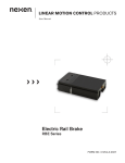
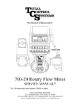
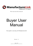
LINEAR MOTION CONTROL PRODUCTS
User Manual
Spring-Engaged Rod/Shaft Lock
RLSS-S
RLSS-C
FORM NO. L-21183-D-1005
In accordance with Nexen’s established policy of constant product improvement, the specifications contained in this
manual are subject to change without notice. Technical data listed in this manual are based on the latest information
available at the time of printing and are also subject to change without notice.
Technical Support:
800-843-7445
(651) 484-5900
www.nexengroup.com
DANGER
Read this manual carefully before installation and operation.
Follow Nexen’s instructions and integrate this unit into your system with care.
This unit should be installed, operated and maintained by qualified personnel ONLY.
Improper installation can damage your system or cause injury or death.
Comply with all applicable codes.
Nexen Group, Inc.
560 Oak Grove Parkway
Vadnais Heights, Minnesota 55127
ISO 9001 Certified
Copyright 1999 Nexen Group, Inc.
2
FORM NO. L-21183-D-1005
INSTALLATION
NOTE: “Rod” and “Shaft” refer to the same feature and
are used interchangeably.
3. Carefully work the new rod past the seal(s) and
through the Rod Lock assembly.
1. Apply a constant supply of at least 4.1 bar (60 PSI)
to the Rod Lock device.
4. When the rod is in the desired position, engage the
lock by removing air pressure.
2. Remove the supplied rod from the inside of the Rod
Lock and keep for future use.
5. A variety of mounting configurations are available;
mount the rod lock as desired. The rod lock unit can
be installed in any orientation: with a cylinder for
the “C” models, or as a stand alone unit for the “S”
models.
CAUTION
Do not engage the Rod Lock without a properly
sized rod in place or damage to the internal
components may result.
ROD MATERIAL
•
Nexen’s Rod Lock must mount to a shaft that is
hardened to a minimum of HRC 60 or hard-chrome
plated to a minimum thickness of 20 microns
[0.0008 in] or damage to the shaft may result.
•
The diameter should lie in the h8 tolerance range.
Reference: USAS B4.1 - 1967(1974)
ISO 286-1 - 1988
ISO 286-2 - 1988
•
The rod must be clean and dry to maintain optimum
holding forces.
•
The surface roughness Rmax should be 1.6 microns
[63 microinch] or better.
•
The rated holding force corresponds to static load
conditions. If the rated value is exceeded, slippage
may occur. Operating dynamic forces must not
exceed the static holding force.
CAUTION
Nexen’s Static Rod Lock is suitable for infrequent dynamic braking (emergency stops)
when used with hardened shaft material. Repeated dynamic stops may cause rod and/or
collar wear, reducing holding forces.
AIR FITTINGS
DANGER
Support the load before disengaging the Rod Lock. Failure to support
the load could result in serious bodily injury.
1. The Nexen rod lock is equipped with a NPT or
BSPT port for the air inlet. Route clean air, using
soft or hard lines, supplying at least 4.1 bar [60 psi]
to facilitate full disengagement.
NOTE: Install the valve in close proximity to the Rod
Lock unit for faster engagement and disengagement.
2. The Nexen rod lock is equipped with a port for the
internal vent (filters are included with most models).
If the air quality around the application is poor, route
the vent of the rod lock to a more suitable area, or
use a filtered breather. Contact Nexen for available
components.
Higher air pressures will also speed the disengagement
time, but do not exceed 8.0 bar [120 psi] air
pressure.
NOTE: Clean air is important for proper Rod Lock
functioning. Debris inside the Rod Lock may inhibit
performance and/or shorten the life of the product.
FORM NO. L-21183-D-1005
3
AIR CONTROLS AND PROGRAMMING
CYLINDER MOUNTING
CAUTION
Minimum release pressure = 4 bar [60 psi]
Maximum pressure = 8 bar [120 psi]
When programming the Nexen Rod Lock
in motion control systems, it is critical to
avoid repeated overlapping conditions
(i.e.: forced motion during the engagement
or disengagement of the Rod Lock). Shaft
damage will result. Design the control
system to use the Rod Lock in static
conditions.
Cylinder functioning is regulated by a 5/3 valve (use
cylinder manufacturer’s recommend Cv valves), center open on the central port and supplied by exhaust
ports.
NOTE: Do not use a valve with a closed center. This
will cause unbalance in the piston if any of the circuits leak.
Nexen’s Rod Lock must mount to a shaft
hardened to a minimum of HRC60 or hardchrome plated to a minimum thickness of 20
microns [0.0008 in] or damage to the shaft
may result.
One-directional flow reducers can be used to control
the speed of the cylinder rod. To ensure fast braking
of the rod, a quick exhaust valve can be installed on or
near the rod lock.
The normally closed (NC) solenoid valve directs the air
supply to the rod lock, keeping it disengaged until the
electrical signal is interrupted.
System Shown: Vertical mounting
with the load on top of the cylinder
Rod Lock
W
Quick Exhaust Valve
Vertical Mounting: The force on the piston must not
exceed its locking capacity when it is combined with
the force of the load.
Use of a 5/3 valve provides a braking effect and maintains accurate rod positioning. Stopping precision is
determined by the rate of speed of the rod and loads
in motion.
Flow Control
Valves
3-Way Valve
Horizontal Mounting: Pressure is maintained on both
sides of the cylinder piston, keeping it balance, preventing displacement of the rod upon release. Use exhaust
ports 3 and 5 (see below).
Lowering
Control
5/3 Valve
STAND-ALONE MOUNTING
Specifications match those of cylinder models listed
above.
System Shown: Cylinder control using a 5/3
valve with the center open on the central port.
4
2
5
3
1
5
3
Flow Control
Valves
Quick
Exhaust
Valve
Inward
Control
12
2
3
1
System Shown: Cylinder control using a 5/3
valve with the center open on the central port.
Rod Lock
Flow
Control
Valves
2
3
Regulator
Figure 1
W
Outward
Control 4
2
Raising
Control
12
Raising
Control
3-Way
Valve
5/3 Valve
Lowering
2 Control
12
4
5
1
Rod
Lock
Quick
Exhaust
Valve
2
3
1
3
W
1
5/3 Valve
Regulator
Figure 2
Figure 3
4
3-Way
Valve
FORM NO. L-21183-D-1005
AIR PREPARATION
For long life, Nexen’s Rod Lock requires clean and pressure regulated air (filtered to five microns or better).
Nexen does not recommend lubricated air for this product.
ROD LOCK ASSEMBLY
RLSS-S MODEL SHOWN
12
3
10
2
1
A
4
8
*
5
7
11
13
6
9
A
ITEM
DESCRIPTION
QTY
ITEM
DESCRIPTION
QTY
1
Housing
1
8
Retaining Ring
1
2
Piston
1
9
Sleeve Bearing
2
3
Friction Collar
1
10
O-ring Seal
1
4
Steel Ball
*
11
O-ring Seal
1
5
End Cap
1
12
O-ring Seal
1
6
Rod Wiper Seal
2
13
Spring
*
7
Retaining Ring
1
17
Shaft
1
Varies with size and model
FORM NO. L-21183-D-1005
5
RLSS-C MODEL SHOWN
12
3
10
2
20
1
A
4
19
6
8
*
5
7
11
13
A
9
ITEM
DESCRIPTION
QTY
ITEM
DESCRIPTION
QTY
1
Housing
1
9
Sleeve Bearing
1
2
Piston
1
10
O-ring Seal
1
3
Friction Collar
1
11
O-ring Seal
1
4
Steel Ball
*
12
O-ring Seal
1
5
End Cap
1
13
Spring
*
6
Rod Wiper Seal
1
17
Shaft
1
7
Retaining Ring
1
19
Guide O-Ring
1
8
Retaining Ring
1
20
Screw Mounting
4
Varies with size and model.
SERVICE RECOMMENDATION
NOTE: The rod lock assembly is designed for extended service life. Due to this long product life, stored spring
energy, and the complexity of the internal components, Nexen recommends that all service be performed by
trained personnel.
Do not attempt to remove the retaining ring and dismantle the rod lock assembly. This product is spring loaded
and under pressure. If the product malfunctions, replace the unit or contact Nexen.
6
FORM NO. L-21183-D-1005
WARRANTY
Warranties
Nexen warrants that the Products will be free from any defects in material or workmanship for a period of 12 months
from the date of shipment. NEXEN MAKES NO OTHER WARRANTY, EXPRESS OR IMPLIED, AND ALL IMPLIED
WARRANTIES, INCLUDING WITHOUT LIMITATION, IMPLIED WARRANTIES OF MERCHANTABILITY AND FITNESS FOR A PARTICULAR PURPOSE ARE HEREBY DISCLAIMED. This warranty applies only if (a) the
Product has been installed, used and maintained in accordance with any applicable Nexen installation or maintenance
manual for the Product; (b) the alleged defect is not attributable to normal wear and tear; (c) the Product has not been
altered, misused or used for purposes other than those for which it was intended; and (d) Buyer has given written notice of the alleged defect to Nexen, and delivered the allegedly defective Product to Nexen, within one year of the date
of shipment.
Exclusive Remedy
The exclusive remedy of the Buyer for any breach of the warranties set out above will be, at the sole discretion of
Nexen, a repair or replacement with new, serviceably used or reconditioned Product, or issuance of credit in the
amount of the purchase price paid to Nexen by the Buyer for the Products.
Limitation of Nexen’s Liability
TO THE EXTENT PERMITTED BY LAW NEXEN SHALL HAVE NO LIABILITY TO BUYER OR ANY OTHER PERSON FOR INCIDENTAL DAMAGES, SPECIAL DAMAGES, CONSEQUENTIAL DAMAGES OR OTHER DAMAGES OF ANY KIND OR NATURE WHATSOEVER, WHETHER ARISING OUT OF BREACH OF WARRANTY OR
OTHER
BREACH OF CONTRACT, NEGLIGENCE OR OTHER TORT, OR OTHERWISE, EVEN IF NEXEN SHALL HAVE
BEEN ADVISED OF THE POSSIBILITY OR LIKELIHOOD OF SUCH POTENTIAL LOSS OR DAMAGE. For all of
the purposes hereof, the term “consequential damages” shall include lost profits, penalties, delay images, liquidated
damages or other damages and liabilities which Buyer shall be obligated to pay or which Buyer may incur based
upon, related to or arising out of its contracts with its customers or other third parties. In no event shall Nexen be liable for any amount of damages in excess of amounts paid by Buyer for Products or services as to which a breach of
contract has been determined to exist. The parties expressly agree that the price for the Products and the services was
determined in consideration of the limitation on damages set forth herein and such limitation has been specifically bargained for and constitutes an agreed allocation of risk which shall survive the determination of any court of competent
jurisdiction that any remedy herein fails of its essential purpose.
Limitation of Damages
In no event shall Nexen be liable for any consequential, indirect, incidental, or special damages of any nature whatsoever, including without limitation, lost profits arising from the sale or use of the Products.
Warranty Claim Procedures
To make a claim under this warranty, the claimant must give written notice of the alleged defect to whom the Product
was purchased from and deliver the Product to same within one year of the date on which the alleged defect first
became apparent.
Nexen Group, Inc.
560 Oak Grove Parkway
Vadnais Heights, MN 55127
800.843.7445
Fax: 651.286.1099
www.nexengroup.com
ISO 9001 Certified
FORM NO. L-21183-D-1005
7