1
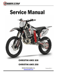
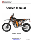
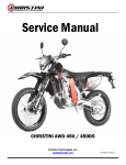
Service Manual
CHRISTINI AWD 300/250
Christini Technologies, Inc.
[email protected]
Version 2012.1
HOW TO USE THIS MANUAL
Read this Manual carefully. You will find it contains all the necessary information for your safety, and that of other persons, as well as guaranteeing the correct conservation and maintenance of the GAS GAS motorcycle that you have
just acquired. You will find all the necessary instructions for the correct riding and control of this vehicle are set out
below. Each message is preceded by a symbol with the following meaning:
WARNING
This warning symbol identifies special instructions or procedures which, if not correctly followed, could result in personal injury or even death.
CAUTION
This symbol identifies instructions or procedures which, if not followed strictly, could result in damage to or destruction of equipment.
NOTE
This note symbol indicates points of particular interest for more efficient and convenient operation.
Motorcycle riding, if improperly conducted, has the potential to cause environmental problems as well as conflicts with
other people. Responsible riding use of your motorcycle will ensure that these problems and conflicts do not develop.
TO PROTECT THE FUTURE OF YOUR SPORT MAKE SURE YOU USE YOUR MOTORCYCLE WHITHIN THE LAW, SHOW CONCERNFOR THE ENVIRONMENT, AND RESPECT THE RIGHTS OF OTHER PEOPLE.
Motorcycle riding is a wonderful sport, and we hope you will enjoy it to the fullest.
Page 2
Table of Contents
General Bike Service
Page 3
Specifications
5
Location of Components
6
Fuel
7
Basic Operating Instructions
9
Maintenance Schedule
12
Ignition
13
Cooling System
14
Spark Plug
17
Transmission Oil
18
Air Filter
20
Throttle Cable
21
Carburetor
21
Clutch
22
Exhaust System
22
Primary Chain
23
Handlebar
25
Brakes
25
Wheels
27
Washing Bike
28
Nut and Bolt Tightening
29
Torque Values
30
Lubrication
31
Tune-Up
32
Storage
35
Troubleshooting
36
Wiring Diagram
39
Table of Contents
AWD Service
Required tools
41
AWD detailed illustration
42
Routine maintenance schedule
44
AWD clutch test
45
AWD sprag test
46
AWD chain removal
47
AWD engagement switch
51
Front wheel removal
56
Front wheel service
58
Fork removal and installation
65
Dropout service
67
Fork spline bearing service
76
Boot Replacement
81
Triple clamp removal
83
Triple clamp service
85
Main drive shaft removal
100
Head tube bearing service
101
Main drive shaft installation
103
Triple Clamp Installation
104
Gearbox removal
108
Gearbox service
109
AWD clutch removal
114
AWD clutch Service
115
Troubleshooting
119
Warranty
120
Page 4
Specifications
Page 5
Location of Components
1- Clutch lever
2– Stop/Start
3- Fuel tank cap
4– Brake fluid reservoir
5– Front brake lever
6– Throttle
7– Clutch fluid reservoir
8– Choke trigger
9- Brake disc
10– Front brake caliper
11- Radiator
12– Shift pedal
13– Primary chain
14– Chain guard
15– Front suspension
16- Gasoline petcock
17– Gas tank
18– Carburetor (behind
AWD chain cover)
19– Muffler (behind panel)
20– Seat
21– Rear shock
22- Rear brake caliper
23- Suspension linkage
24- Rear brake pedal
25- Kick-start
26– Exhaust
Page 6
Fuel
The GAS GAS EC 2-cycle engines require a mixture of gasoline and oil. Use gasoline with an octane rating
equal to or higher than that shown in the table.
NOTE
If knocking or pinging occurs, try a different brand of gasoline
or higher octane grade.
WARNING
Gasoline is extremely flammable and can be explosive under certain
conditions. Always stop the engine and do not smoke. Make sure
the area is well ventilated and free from any source of flame or
sparks; this includes any appliance with a pilot light.
Mixing oil inside the engine
Oil must be mixed with gasoline to lubricate the piston, cylinder, crankshaft, and connecting rod bearings.
Recommended oil:
2-CYCLE SYNTHETIC
NOTE
If the recommended oil is not available, use only oil designed
for racing with 2-cycle engines.
Gasoline and engine oil mixing proportions:
Synthetic oil 100%: gasoline 50, engine oil 1 = 2%
Semi-synthetic oil: gasoline 50, engine oil 1 = 2%
Mineral oil: gasoline 32, engine oil 1 = 3%
Page 7
Fuel
CAUTION
Do not mix vegetable and mineral based oils.
Too much oil will cause excessive smoking and spark plug fouling.
Too little oil will cause engine damage or premature wear.
CAUTION
Below 0 ºC do not use 100% synthetic oil.
To prepare the mixture, first pour oil and half of the gasoline used into a container and stir the mixture thoroughly. Then add the rest of the gasoline and stir the mixture well.
NOTE
At low temperature, oil will not easily mix with gasoline. Take
time to ensure a well-blended mixture.
The lubrication quality of this mixture deteriorates rapidly; use
a fresh mixture for each day of operation.
Page 8
Basic Operating Instructions
1. Make sure the motorcycle is in the neutral position.
2. Turn the gasoline cock (A) clockwise to the "ON" position.
3. If the engine is cold, pull up the choke trigger (B).
NOTE
- When the engine is already warm or on hot days, open
the throttle instead of using the choke knob.
- If the engine is flooded, kick with the throttle fully open.
- If the clutch lever is pulled, the motorcycle can be
started while in any gear.
4. Start the motorcycle with kick-start pedal (C) or push the
start button ( D).
5. Even after the engine starts, keep the choke knob pulled
up.
Stopping the engine
1. Shift the transmission into neutral.
2. After racing the engine slightly, close the throttle completely and depress the engine stop button (E).
Page 9
Basic Operating Instructions
Shifting Motorcycle
The transmission is a 6-speed, of the return shift type. A return shift
means that to go from first gear to third gear it must go first through
the second gear, that is to say that it upshifts gears one by one. To
engage first gear from neutral, pull the clutch lever in and push
down on the gearshift pedal (A), then release the gearshift pedal
and gently release the clutch lever.
CAUTION
When shifting gears, press firmly on the gearshift pedal to ensure a positive shifting. Careless, incomplete
shifts can cause the transmission to jump out of gear and cause engine damage.
Stopping Motorcycle
For maximum deceleration, close the throttle (A) and apply both
front and rear brakes. Disengage the clutch as the motorcycle
comes to a stop. Independent use of the front or rear brake may be
advantageous under certain conditions.
Downshift progressively as speed is reduced to ensure good engine
response when you want to accelerate.
BreakBreak-In
A break-in period is necessary to ensure a smooth operation and obtain an optimum engine and the transmission responses. During the first hour or 20 km of operation, run the engine at low and moderate speeds
and revolutions per minute (RPM).
NOTE
The slow riding necessary during the break-in period may cause carbon deposits to build up on the spark
plug and foul it.
Page 10
Basic Operating Instructions
If inspection of the spark plug shows this to be the case, replace the standard spark plug with another of a
higher heat range.
Perform the break-in period following these steps:
1. Start the engine and let it run at idle until the engine is warm.
2. Stop and let the engine cool completely.
3. Start the engine and ride for 10 minutes at moderate speed -NEVER ACCELERATE HARD.
4. Stop and let the engine cool completely. Be sure to check and
adjust chain slack and spoke tightness and carry out a general inspection.
5. Start the engine and ride for 20 minutes at moderate speed. -NEVER ACCELERATE HARD.
6. Stop and let the engine cool completely. Check and adjust as needed (Refer to the table of adjustments).
7. Install the removed parts.
8. Fill the radiator with the recommended coolant. Before starting the motorcycle, bleed the air from the
cooling system.
9. Start the engine and ride for 30 minutes at moderate speed.
10. Stop and let the engine cool completely. Check and adjust.
11. After the break-in procedure has been properly carried out, the motorcycle is ready for regular operation.
CAUTION
However, avoid accelerating recklessly which can lead to engine failure. Be careful to use the necessary
skills and techniques while operating the motorcycle.
NOTE
After the break-in period, install a new set of standard spark plugs.
Page 11
Maintenance Schedule
The maintenance and adjustments in this table are easy to follow and must be carried out to keep the motorcycle in good running condition.
NOTE: (*) Inspect and carry out these operations only if it is necessary.
Page 12
Electronic Ignition
This motorcycle uses a capacitor discharge ignition system
(CDI). The ignition system should never require adjustment
unless the stator of the magnetic flywheel was incorrectly
installed during engine reassembly. If necessary, inspect
and adjust as follows:
Adjustment
- Remove the magnetic flywheel cover.
- Make sure that the mark on the stator plate is aligned with
the mark on the crankcase.
- If the marks are not aligned, loosen the magnetic inertia
wheel screws and turn it.
- Tighten the screws securely.
- Install the magnetic flywheel cover.
NOTE
Engine tune-up can be adjusted to match the rider´s preferences and skills.
- Remove the magnetic flywheel cover.
- Loosen the stator screws.
- Adjust the engine tune-up by changing the position of the stator within prudent limits
NOTE
For the best engine performance, it is very important to adjust the engine tune-up within the set of limits
described.
- Tighten the stator screws.
- Install the magnetic flywheel cover.
- Test ride the motorcycle and readjust the engine tune-up, if necessary.
Page 13
Cooling System
Radiator Hoses
Check the radiator hoses for cuts or deterioration, and the connections for looseness and leaks.
Radiator
Check the radiator fins for obstructions (insects or mud). Remove any obstructions with a stream of low water pressure.
CAUTION
If high water pressure is used the radiator fins could be damaged and impair the radiator effectiveness.
Do not obstruct or deflect airflow through the radiator by installing unauthorized accessories. Any interference with the radiator airflow can lead to engine overheating and damage.
Coolant information
To protect the cooling system aluminum parts (engine and radiator) from rust and corrosion, the use of corrosion and rust inhibitors chemicals in the coolant is essential. If rust inhibitors were not used, over a period of time the radiator will be corroded. This will clog the tubes of the cooling system.
CAUTION
Use of incorrect coolant solutions will cause engine and cooling system damage. Use coolant containing
corrosion inhibitors made specifically for aluminum engines and radiators in accordance with the instructions of the manufacturer.
WARNING
Chemical liquids are harmful to the human body. Follow manufacturer instructions.
CAUTION
Distilled water must be used with corrosion inhibitors and the antifreeze in the cooling system. If tap water
is used in the system, the cooling tubes can be clogged and reduce the cooling system
efficiency.
If the lowest ambient temperature encountered falls below the freezing point of water, protect the cooling
system. Use a permanent type of antifreeze in the cooling system (distilled water and ethylene glycol and
corrosion inhibitors for aluminum engines and radiators). For the coolant mixture ratio under extreme conditions, choose the mixture ratio listed on the container for the lowest ambient temperature.
CAUTION
Permanent types of antifreeze have anticorrosion and anti-rust properties. When it is diluted excessively, it
loses its antifreeze and anticorrosion properties. Mix in accordance with the instructions of manufacturer.
Liquid recommended
Permanent type of antifreeze (distilled water and ethylene glycol) plus corrosion inhibitors for aluminum
engines and radiators.
NOTE
Initially, at the factory a permanent type of antifreeze is installed in the cooling system. It is colored green,
it contains a 50% solution of ethylene glycol, and has a freezing point of –35 ºC.
Page 14
Cooling System
Coolant recommended
Coolant absorbs excessive heat from the engine and transfers it to the air at the radiator. If the coolant
level is low, the engine overheats and may suffer severe damage. Check the coolant level each day
before riding the motorcycle. Add liquid recommended if the level is low (see next page).
WARNING
To prevent severe scalding do not remove the radiator cap or try to change liquid, when the engine is still
hot. Wait until it cools.
Coolant level
- Place the motorcycle in riding position.
- Turn the radiator cap counterclockwise and wait a few seconds until vapors inside are released. Then push and turn it
further in the same direction and remove the cap.
NOTE
Check the level when the engine is cold.
- Check the coolant level. The coolant level should be just at a level below the cap rubber seal.
- If the coolant level is low, add the correct amount of coolant through the filler opening.
Total quantity
Mix antifreeze and distilled water 1:1 (distilled water 50%, antifreeze 50%).
Capacity: 1.1 L
Coolant Replacement
Coolant should be changed periodically to ensure long engine
life.
- Wait for the engine to cool completely.
- Place the motorcycle in riding position.
- Remove the radiator cap.
- Place a container under the coolant drain screw, and drain
the coolant from the radiator and engine by removing the drain
screw (B) at the bottom of the water pump cover (A). Wash off
immediately any coolant spilled on the chassis, engine, or
wheels.
Page 15
Cooling System
WARNING
If coolant gets on the tires will make them very slippery and can cause an accident.
- Visually inspect the old coolant. If whitish spots are observed in the liquid is a clear indication that the
aluminum parts in the cooling system are corroded. If the coolant is brown, iron or steel parts of the system
are rusting. In both cases, flush the cooling system.
- Check the cooling system for damage, leaks or missing gaskets in the cooling system.
- Install the water pump cover drain screw with the specified torque values shown in the table. Always replace the gasket with a new one.
Drain plug tightening torque (refer to torque table)
Water pump screw: 9 Nm
-
Fill the radiator up to the edge of the cap with coolant, and install the radiator cap.
Inspect the cooling system for leaks.
Start and warm up the engine, then stop the engine.
Check the coolant level after the engine cools down. Add coolant up to the cap.
Page 16
Spark Plug
The standard spark plug is a shown in the table and should be tightened to 27 Nm.
The spark plug should be removed periodically to check its gap. If the plug is oily or has carbon deposits,
clean it with a sandblaster. After removing the abrasive particles, the spark plug must be cleaned using a
wire brush or a similar tool. Measure the gap with a feeler gauge, if incorrect adjust the gap by bending the
side electrode. If the spark plug electrodes are corroded or damaged, or if insulator is cracked, replace the
plug.
NOTE
Inspect every 30 hours and change every 60 hours.
To find out whether the right heat range plug is being used, remove it and inspect the ceramic insulator
around the center electrode. If the ceramic is light brown, the spark plug is correctly matched to engine
temperature. If the ceramic is white, the spark plug should be replaced with the next colder plug. If the ceramic is black, the spark plug should be replaced with the next hotter plug.
NOTE
If the engine performance drops, replace the spark plug first to recover its output.
Page 17
Transmission Oil
For the transmission and clutch to function properly, maintain the transmission oil level at the optimum
level and change it periodically. A motorcycle with insufficient transmission oil, deteriorated or contaminated can accelerate wear and tear and cause transmission.
Oil level inspection
- Wait a few minutes if the motorcycle has been operating.
- Check the oil level through the inspection window in the lower
right hand side of the engine (A).
- Oil level must be kept between the maximum and minimum
marks.
- If the lever is too high, you have to remove the excess oil through
the drain plug (B).
- If the level is low, add the necessary quantity of oil by opening the plug (C). Use the same type and oil
manufacturer used currently with the engine.
Transmission Oil
Viscosity: SAE 10W30
Capacity:900 cc (EC250-300)
Page 18
Transmission Oil
Oil change
NOTE
The engine must be completely cool and then warm up the engine again for a few minutes to normal operating temperature, to register the correct engine oil temperature and to obtain an accurate oil level measurement.
- The transmission oil should be changed periodically to ensure
long engine life.
- Warm up the engine for 5 minutes so any oil sediment will float.
- Stop the engine, and place an oil pan under the engine.
- Remove the drain screw (B) and place the motorcycle in riding
position to allow the oil to drain out.
- Clean the drain screw magnet of any iron particles.
- Tighten the oil drain screw with its O-ring to 20-Nm.
- Remove the oil filler opening plug (C) and pour 900 cc of new
transmission oil for the models 250 / 300.
- Check the oil level, after kicking the kick-start pedal 3 or 4 times.
- Install the oil filler opening plug.
Page 19
Air Filter
A clogged air filter restricts the engine air intake, increasing fuel consumption, reducing engine power, and
causing spark plug fouling.
WARNING
A clogged air filter may allow dirt and dust to enter the carburetor and stick the throttle open. This could
cause an accident. A clogged air filter may allow dirt and dust to enter the engine causing excessive wear
and tear and other damages. Do not omit checking the element, before and after each race or practice
session. Clean it if necessary.
Element Cleaning
WARNING
Clean the element in a well-ventilated area, and make sure that there are no sparks or flame anywhere
near the working area (this includes any appliance with a pilot light). Do not use gasoline to clean the element because could cause an explosion. To access the air filter, remove the seat by removing the bolt that
secures it.
To access the air filter, remove the seat by removing the bolt that
secures it.
- Remove the cover.
- Remove the screw (A) and remove the filter (B).
- Place a lint-free towel in the intake port of the carburetor so no dirt
is allowed to enter the carburetor.
CAUTION
Do not turn the filter since it can be easily damaged or torn.
- Wipe out inside the air filter housing with a clean damp towel.
- Pull the cage (B) out of the air filter (A).
- Clean the filter using a soft bristle brush in a bath of filter cleaning
fluid.
- Squeeze it dry with a clean towel. Do not wring the element or
blow it dry since it can be damaged.
- Inspect the filter for damage such as tears, hardening, or shrinkage. If damaged, replace it or it will allow dirt into the carburetor.
- Apply grease to all connections and screws in the air filter and
intake ports.
- Install the filter in the cage and pack the filter lip with grease (A),
to ensure good sealing and prevent dirt entrance.
- Install the air filter in the motorcycle and make sure it is correctly
secured.
Page 20
Throttle/Carburetor
THROTLE CABLE
- Check that the throttle grip turns smoothly.
- Check that the throttle grip has 2-3 mm of free play.
- If the free play is incorrect, loosen the locknut on the
upper end of the throttle cable, and turn the adjuster to
obtain the correct amount of free play.
- Tighten the locknut again.
- If the free play cannot be set by adjusting the cable, remove the cable protector in the throttle body. Make the
necessary free play adjustments with the tensor at the
end of the cable, tighten the locknut, and reinstall the
protector.
CARBURETOR
Idle speed adjustment
Is carried out using the air screw (A) and idle screw (B).
- First turn in the air screw until it is loose, then tighten it
1 1/2 turns.
- After thoroughly warming up the engine, turn the idle
adjusting screw to obtain the desired idle speed. If there
are no idle preferences, turn the screw until the engine
stops.
- Tighten lightly the idle screw.
- Open and close the throttle a few times to make sure the idle speed does not change. Readjust if necessary.
- With the engine idling, turn the handlebar to each side. If handlebar movement changes the idle speed,
the throttle cable may be improperly adjusted or routed incorrectly, or it may be damaged. Be sure to correct any of these conditions before riding.
WARNING
Riding with a damaged throttle cable could be dangerous.
Page 21
Clutch/Exhaust
CLUTCH
The clutch lever should have a maximum play of 3 mm. This
margin increases with the wear on the clutch plate.
To adjust, proceed as follows:
- Use bolt A to adjust the lever’s range of movement to the
rider’s convenience.
- Adjust the play of the lever using bolt B.
WARNING
- Maintain the clutch lever with the play shown, otherwise the performance and useful life of the clutch
may be adversely affected.
- This model uses mineral oil GRO ULTRA 5 for the clutch hydraulic circuit.
- Tank C must not be filled with brake liquid.
EXHAUST SYSTEM
The exhaust and the muffler reduce the noise and send gases
away from the rider. If the exhaust is badly damaged, dented,
cracked or rusted, replace it with a new one. Replace the muffler
fiber if the exhaust noise becomes too loud or if the engine performance drops.
Muffler replacement
- Remove the retaining screws of the right side number-posting
cover.
- Remove the retaining screws (A) of the muffler (B) and remove
the muffler towards the rear.
- Separate the silencer from the joint (see arrow).
- Replace the muffler and reinstall the assembly.
Changing the silencer packing
- Remove all three screws.
- Remove the inside core of the muffler.
- Replace the muffler fiber by wrapping it around the inner tube.
- Reinstall the assembly.
-(A). Screw.
-(B). Silencer.
Page 22
Primary Chain
DRIVE CHAIN
The drive chain must be checked, adjusted, and lubricated in accordance with the Maintenance Schedule.
If the chain is worn or adjusted incorrectly (either too loose or too tight) the chain could become loose or
break. Replace the chain, if necessary.
WARNING
A chain that breaks or becomes loose could snag on the engine or on the rear wheel, severely damaging
the motorcycle and causing it to go out of control.
Drive Chain Slack Inspection
The space between the chain and the swingarm at the same
height of the chain slider should be 30-50 mm. Rotate the
rear wheel to find the place where the chain is tighter. Adjust
the drive chain if it has too much or too little slack. In addition to checking the slack, rotate the rear wheel to inspect for
damaged rollers, loose pin and links, unevenly or excessively
worn teeth, and damaged teeth.
Drive Chain Slack Adjustment
- Loosen the rear axle nut (A).
- Turn the nuts on the chain adjusting tensors (B) until the
drive chain has a gap of 30-50 mm between the chain and
the swing arm. To keep the chain and wheel aligned, the left
chain tensor should aligned with the right chain tensor.
WARNING
Misalignment of the wheel will result in abnormal wear and
may cause an unsafe riding condition.
NOTE
Wheel alignment can also be checked using the string method.
- Tighten the chain tensor nuts (B).
- Tighten rear axle nut to 98 Nm.
- Rotate the wheel, measure the chain slack again at the tightest position, and readjust if necessary.
Page 23
Primary Chain
WARNING
If the axle nut is not securely tightened an unsafe riding condition may result.
Drive chain, chain guide, chain slider, and rear sprocket teeth.
When the chain is worn so much that it is more than 2% longer than when new, it is no longer safe for use
and should be replaced. Whenever the chain is replaced, inspect both the engine output pinion and rear
sprocket teeth, and replace them if necessary. Worn sprocket teeth will cause a new chain to wear quickly.
NOTE
When a part is worn, replace it with a genuine part for maximum resistance and safety.
To minimize any chance of the master link coming apart, the master link clip must be installed with the
closed end of the «U» facing in the direction of the chain rotation.
Chain Guide Slider
Visually inspect the upper and lower chain slider at the
location of the swingarm. If damaged or worn, replace it
with a new part.
(A). Chain Guide Slider.
(B). Swingarm.
Pinion Teeth, Pinion Sprocket and Sprocket Wear
Visually inspect the pinion teeth. If they are worn or damaged, replace the pinion or the sprocket.
Lubrication
Lubrication is necessary after riding through rain or in the mud,
or any time that the chain appears dry. A heavy oil is preferred to
a lighter oil because it will stay on the chain longer and provide
better lubrication.
Apply oil to the sides of the chain rollers for better oil penetration.
Wipe off any excess oil.
Page 24
Handlebar/Brakes
HANDLEBAR
To suit various riding positions, the handlebar position can be
adjusted front to rear.
Handlebar position adjustment
Loosen the handlebar holder (A) screws (B), turn the handlebar
and place it in the desired position.
Tighten the bolts, front first and then the rear, to 25 Nm of
torque.
If the handlebar is installed correctly, there will be an even gap
at the front and rear after tightening (A).
BRAKES
Disc and disc pad wear is automatically compensated for and has no effect on the brake lever or pedal action. So there are no parts that require adjustment on the brakes except brake lever free play and brake
pedal position
Front brake lever free play
Adjust the front brake lever (A) to match your requirements. To adjust, loosen the nut (B). After adjustment,
tighten it securely. Then check that the brake response
is correct.
Rear brake pedal position
When the brake pedal is in rest position, there should be a free
play of 10 mm. Check the brake for good braking power and no
brake drag.
(A). Brake pedal.
(B). 10 mm free play.
WARNING
If the brake pedal feels spongy when it is applied, there might be air trapped in the brake pump or the
brake may be defective. Since it is dangerous to operate the motorcycle under such conditions, have
the brake checked immediately.
Page 25
Brakes
Brake fluid
Inspect the brake fluid level and change it periodically. The brake fluid should also be changed if it becomes contaminated with dirt or water.
Liquid recommended: D.O.T 3 or D.O.T 4.
Brake fluid level inspection
The front (A) and rear (B) reservoirs must be kept more than half full with brake fluid. If the brake fluid is
insufficient, add brake fluid.
CAUTION
Do not spill brake fluid onto any painted surface. Do not use fluid from a container that has been left open
or that has been unsealed for a long time. Check for fluid leakage around the fittings. Check for brake hose
damage.
WARNING
Do not mix different types of fluid. Change the brake fluid in the reservoirs completely if the same type of
brake fluid is not available.
Brake wear inspection
If the thickness of either pad, front and rear, is less than 1 mm, replace both pads as a set. Pad replacement should be carried out only by an authorized dealer.
Page 26
Wheels
WHEELS
Tires
- Tire pressure affects traction, and tire life.
- Adjust the tire pressure to match road conditions and rider’s preference, but do not stray too far from the
recommended pressure.
NOTE
Tire pressure should be checked when the tires are cold before riding.
Road conditions
- When the road is wet, muddy, sandy or slippery, reduce the tire pressure.
- On gravel roads or hard terrain, increase the tire pressure.
Spokes and wheel rims
The spokes on both wheels must be tightened evenly and should not be allowed to have free play. Unevenly
tightened or loose spokes will cause wheel rim run out, the other spokes will be stressed and might break.
Wheel rim run out
Place a dial indicator at the rim side, and spin
the wheel by hand to measure the axial run out.
Place the dial indicator at the inner circumference of the wheel and spin the wheel, the difference between the highest and lowest quantities
is the run out. If the run out is not excessive it
can be corrected tightening or loosening some
spokes with the spoke adjusting wrench (B). If
the wheel rim is curved or bent it must be replaced.
NOTE
A welded area on the rim may indicate excessive run out. Disregard this when measuring rim run out.
Page 27
Washing Bike
1- Preparation for washing
Before washing the motorcycle, precautions must be taken to prevent water from entering the following
parts of the motorcycle:
Exhaust: Cover it with a plastic bag tightened with rubber bands.
Clutch and brake levers, hand grips, and engine stop button:
Cover these parts with plastic bags.
Air cleaner intake: Cover the opening with tape or with a rag.
2- Where to be careful
Avoid spraying water with any great force near the following areas:
- Brake calipers and brake pump piston.
- Ignition coil or into the spark plug cap.
- Front and rear wheel hubs.
- Steering bearings.
- Rear suspension system.
- Swingarm bearings
CAUTION
To avoid excessive ageing of the plastic parts and other washable pieces of the motorcycle, it is suggested
that these items must be washed carefully. If the washer applies water at high pressure and/or temperature, take the precaution of maintaining the washer outlet gun at a distance of 30 centimeters minimum,
this will ensure the correct gloss of the plastics and maintain adherence of the self-adhesive labels that
decorate the motorcycle.
3- After washing
- Remove the plastic bags, and clean the air cleaner intake.
- Lubricate the points listed in the lubrication section
- Start the engine and let it run for 5 minutes.
- Check the brakes before operating the motorcycle.
WARNING
Never wax or lubricate the brake disc. Loss of braking and an accident could result. Clean the disc with
trichloroethylene or acetone.
Page 28
Nut and Bolt Tightening
Before each ride, check the condition of the components below and make sure all bolts and nuts are properly tightened:
1- Front and rear wheel
2- Front fork
3- Handlebar
4- Clutch lever holder screw
5- Spark plug
6- Cylinder head bolt
7- Cylinder nuts
8- Swingarm shaft nut
9- Air box screw
10– Rear sprocket bolts
11– Chain adjuster nut
12– Chain guide bolts
13– Subframe bracket bolts
14- Gearshift pedal bolt
15- Engine holder bolts and
nuts
16– Radiator bracket bolts
17– Front caliper bolts
18– Front axle nut
19- Spokes
20– Seat mounting bolts
21– Rear shock bolt
22- Subframe bolts
23– Brake lever bolt
24– Fork pinch bolts
25– Exhaust mounting bolts
26– Kick-start bolt
27- Rear brake pedal bolt
28– Torque rod mounting bolt
29– Linkage mounting bolt
30– Rear axle bolt
Page 29
Torque Values
Torque Values Table
Tighten all bolts and nuts to the proper torque using an adequate wrench. A bolt or nut loose might damage
the motorcycle or even cause an accident.
Page 30
Lubrication
LUBRICATION
Lubricate the points shown here, apply either engine oil or grease, periodically or whenever the vehicle has
been operated under wet or rainy conditions, and especially after using high water pressure. Before lubricating each part, remove any rusty spots with rust remover and wipe off any grease, oil, or dirt.
General lubrication:
- Clutch lever (A).
- Front brake lever (B).
- Rear brake pedal (C).
- Rear brake bearing (D).
- Gearshift pedal (E).
Use an aerosol with a tube for pressure lubrication and apply grease inside the gas cable (A).
Drive Chain Lubrication
Lubricate the drive chain after driving on wet terrain or
when the chain looks dry. A high viscosity oil is preferred
rather than a lower viscosity because it will stick to the
chain longer and lubricate the chain better.
Apply oil to the sides of the chain rollers (A) for better oil
penetration. Wipe off any excess oil.
Page 31
Tune-up
1. CARBURETOR TUNETUNE-UP
Mixture
First step is to establish a basic knowledge on the identification and operation of carburetor components.
Change settings in accordance with the temperature:
NOTE
The main jet should be increased or decreased 1 to 5 sizes and tested until the engine gives maximum
power.
Main jet
It has a great overall effect. The number stamped on lower part of
the main jet indicates the size of the hole metering fuel. A greater
number corresponds to a bigger hole which supplies more fuel.
WARNING
Gasoline is extremely flammable and can be explosive under certain conditions. Always stop the engine
and do not smoke. Make sure the area is well ventilated and free from any source of flame or sparks (this
includes any appliance with a pilot light).
Idling nozzle and mixture adjustment screw
Controls the mixture from the closed position to an
opening of 1/8 of throttle range, but has little effect on
full throttle. To adjust the mixture in this range, the air
screw can be turned to change the air flow through the
circuit, or the slow jet can be changed to provide more
or less fuel. Start by turning the air screw. Screwing it in
richens the mixture. The air screw must be turned from
a lightly seated position. Make changes in 1/2 turn increments. If turning the screw between 1 and 2.5 turns
does not give the desired results, change the slow jet
(B) one step and tune up with the air screw (A).
Page 32
Tune-up
Carburetor jet needle
The jet needle and jet needle hole together have their greatest effect in the onehalf throttle range. The needle moves in and out of the jet needle hole; since the
needle is tapered, its position in the jet determines the amount of fuel allowed
to flow. There are five grooves in the upper section of the needle where a
circlip fits. This clip locates the needle in the throttle valve and determines its
relative position in the jet needle hole, and provides a rich mixture. Moving the
clip to the top will provide a lean mixture. Change the clip position one step at a
time. The straight area of the needle affects throttle valve response in the small
openings range.
Test runs with the motorcycle
- Warm up the engine with the carburetor at the standard setting, and inspect the operating conditions of
the spark plug.
- Test-ride the motorcycle with the throttle opened.
Symptoms of improper settings
If your motorcycle exhibits one of the following symptoms the changes must be adjusted. Before attempting
any changes, make sure that everything else is in good operating condition.
Check the condition of the spark plug, make sure the ignition timing is correct, service the air cleaner element, decarbonize the exhaust tube.
If your machine has run properly up to this point, it is possible that the problem is elsewhere; changing the
carburetor settings in such a case would probably be a waste of time.
- Set the carburetor so that the engine delivers satisfactory power with the throttle valve opened.
- If the air-fuel mixture is too lean, the engine tends to overheat and may be seized. On the other hand, if it
is too rich, the spark plug easily gets wet and causes misfires. The proper mixture varies depending on atmospheric conditions. Taking these conditions into consideration, adjust the carburetor settings properly.
NOTE
Keep in mind that the carburetor components that regulate fuel flow and the screw that control the flow of
air must be tight.
Page 33
Tune-up
The standard competition measurements EC 250 are an example.
Correction factors:
(For altitude or temperature changes).
1. Find the correction factor to adjust the carburetor.
Example: 1000 meters altitude with an air temperature of 35°C.
The correction factor is 0.94.
2. Using the correction factor, select the correct slow jet and main jet.
Example: For a correction factor of 0.94 multiply the jet size by that number.
Main jet: # 180 x 0.94 = # 170.
3. Find the correction factor on the Jet Needle / Air Screw chart and change the jet needle clip position and
air screw opening as indicated.
- Jet needle clip setting: from the 3rd groove to the 2nd groove.
- Air screw opening: 1 1/2 + 1 turn = 2 1/2 turns out.
NOTE
For the following recommendations to be accurate, you must use the standard settings as a base-line. Also
do not change any of the settings until you have determined what changes are necessary. All specifications
are based on the use of the fuel and oil specified.
Page 34
Storage
STORAGE
For extended storage of the motorcycle, you must do the following:
- Clean the motorcycle thoroughly.
- Start the engine for about 5 minutes to warm up the transmission oil and then
drain it (refer to the transmission section).
- Fill with new transmission oil.
- Empty the fuel tank (gasoline will deteriorate if left too long).
- Disconnect the battery.
- Lubricate the drive chain and all cables.
- Cover all unpainted metal surfaces with a coat of oil to prevent rust, do not
apply oil to the brakes and rubber parts.
- Cover the exhaust pipe with a plastic bag to prevent corrosion.
- Place the motorcycle in such a position so that the wheels do not touch the
ground (if this is not possible, place cardboards under the wheels).
- Cover the motorcycle to protect it from dust and dirt.
When starting off after an extended storage:
- Remove the plastic bag from the exhaust pipe.
- Tighten the spark plug.
- Fill the fuel tank.
- Check all points marked in the section “Daily Inspection Before Riding”.
- General lubrication.
- Connect the battery.
Page 35
Troubleshooting
TROUBLESHOOTING
NOTE
This is not an exhaustive list of malfunctions, it only shows the most common problems.
Page 36
Troubleshooting
Page 37
Troubleshooting
Page 38
Wiring Diagram
Page 39
AWD Service
AWD Service Section
Page 40
Required Tools
The Tools You Will Need for Maintenance
Page 41
•
Socket set, metric
•
Pliers set
•
Ball peen/ dead blow hammers
•
Soft tip metal punch (brass/aluminum)
•
Screw driver set
•
AWD clutch wrench (optional)
•
Open ended wrenches, metric
•
Allen key set, metric
•
Snap ring pliers, 45 or 90 degree
•
Bearing punch set
•
Blind side bearing removal kit (Motion Pro 08-0292)
•
2 large adjustable wrenches
•
Torque wrench 0-75 ft-lbs
•
Split bearing puller
•
Small pick or awe
•
Safety wire pliers
•
Safety wire .032”
•
Grease gun (included with bike purchase, customer must supply grease below)
•
Shell Albida EP1 Lithium grease (do not substitute)
•
Spectro SPL grease or equivalent
•
Blue Loctite #242
•
Red Loctite #262
•
Green Loctite #609
AWD Detail Illustration
Page 42
Warnings
•
Do not adjust the choke while the bike is moving!
•
Do not over tighten the front axle as it can damage the inside Axle Clamp Bearings.
•
Do not engage the AWD system while at high speeds. Disengagement of the
AWD system can occur at any speed.
•
Be cautious when power washing bike, especially around front drive hubs and
AWD seals. Spraying high pressure water into these areas can damage seals and
bearings.
Page 43
Routine Maintenance
Pre-ride check list:
•
Check secondary AWD chain tension.
•
Lube secondary AWD chain.
•
Check clutch setting (see “AWD Clutch Test” section).
•
Check front wheel for proper function (see “Front Wheel Sprag
Test” section)
•
Check front wheel rim lock nut torque.
As Needed
•
Replace bearings if excessive noise or friction develops.
•
Lubricate spline shafts through grease port with supplied grease
gun and Shell grease.
•
Replace worn or damaged seals and boots.
AVOID:
•
Pressure washing the dropouts, head tube area, side bar
and main gearbox.
Page 44
AWD Clutch Test
•
Place the bike on a stand and make sure that the front wheel
is not touching the ground.
•
Shift the bike into gear.
•
Turn the AWD switch to the on position and check to make
sure the AWD is engaged.
•
Grab the front wheel with two hands and try to spin it backwards. The front wheel should spin backwards but require a
large amount of effort to do so. If the wheel will not break
free, the clutch is set too high. If the wheel turns backwards
very easily, the clutch is set too low.
•
If the clutch needs to be adjusted, pull the gas tank off the
bike.
•
Loosen the set screw on the clutch locknut.
•
Turn the locknut in or out a 1/2 turn at a time until the front
wheel moves backward with the correct amount of force. To
keep driveshaft from spinning apply front brake.
•
Make sure the set screw is positioned over a flat in the clutch
hub and tighten the set screw down and reinstall the tank.
Page 45
Front Wheel Sprag Test
Note: Before performing this test, make sure the AWD Clutch is set
correctly.
•
Place the bike on a stand and make sure that the wheels are not
touching the ground.
•
Turn the AWD switch to the on position and check to make sure
the AWD is engaged.
•
Center the handlebars.
•
Hold down the front and rear brakes.
•
Turn handlebars to the left and back to center. There should be
steering resistance from the AWD system when this is performed.
•
Release brakes and center handlebars.
•
Hold down front and rear brakes again and turn handlebars to the
right and back to center. There should be steering resistance
from the AWD system.
•
If no resistance is felt, or there is only resistance in one direction,
check the front wheel to ensure the sprag bearings are not slipping or damaged. See “Front Wheel Service” section.
Page 46
Cover and Chain Removal
Page 47
Cover and Chain Removal
Page 48
Cover and Chain Removal
•
Remove the 6 cover bolts with an 8mm socket or t-handle and pull
cover off of the frame.
•
To remove the chain, pull the tensioner back with a flat blade
screwdriver and pull the sprocket out with fingers or non-marring
pliers. Remove the chain from countershaft sprocket.
•
Check the following and replace if needed:
1. Sidebar bearing and cover bearing should be smooth turning.
2. Check engagement spline action by engaging and disengaging switch on handle bars.
3. Sidebar seal and cover seal for wear.
4. Excessive wear on chain tension block.
Warning: Do not use an O-ring chain as there is not enough
clearance for one and it would rub the frame.
Page 49
Cover and Chain Removal
•
Reinstall chain and top sprocket.
•
Adjust chain tensioner using a 4mm Allen wrench and by sliding
the tensioner up the sidebar until the front side of the chain has
roughly 10-15mm (0.4-0.6in) of give when pressure is applied.
•
Replace chain cover. Torque sidebar cover bolts to 8 ft-lb.
Note: If cover does not seat on the sidebar, the top sprocket is
not fully seated in the bearing.
Page 50
AWD Engagement
Page 51
AWD Engagement Installation
•
Grease engagement retaining washer.
•
Insert washer into the back of the gearbox using a pick so it sits
flush against the input gear retaining ring.
•
Insert the small fitting from the engagement cable through the
center hole in the back of the gearbox and feed it through until it
sticks out the front of the sidebar.
Page 52
AWD Engagement Installation
•
Grease the engagement spring and spline.
•
Feed the engagement cable through the spring and spline.
•
Insert the cable fitting onto the end of the cable and seat the fitting into the engagement spline bearing.
Page 53
AWD Engagement Installation
•
Seat the cable housing into the back of the gearbox.
•
Slide the other end of the cable into the engagement switch.
•
Line up the engagement spline with the input gear inside the gearbox and push the spline into the gear.
Page 54
AWD Engagement Installation
•
Position the switch so the lever is positioned towards the rider (on)
and slide the housing into the end of the switch.
Note: If there is not enough slack to seat the cable, make sure the
engagement spline is pushed all the way into the gearbox and the barrel adjuster on the cable is turned in completely.
•
Insert the secondary sprocket into the sidebar and make sure it is
fully seated.
•
Position the engagement lever towards the rider (on) and turn the
barrel adjuster out until the engagement spline just starts to pull
away from the stop snap ring.
•
Push the lever to the off position. Make sure the secondary
sprocket is fully seated. Spin the secondary sprocket to verify that
the spline has fully disengaged from the sprocket and it spins
freely.
Page 55
Front Wheel Removal
Note: Due to AWD hub design, front wheel removal and installation is
aided by removing front caliper first.
•
Remove front brake caliper (note: do not squeeze front brake
lever while caliper is off.
•
Remove axle bolt from axle.
•
Loosen axle pinch bolts on both sides of dropout.
•
Slide axle through wheel and remove.
•
Remove front wheel from dropouts.
Note: The hub inserts will not fall out like the spacers on a normal hub.
They will also rotate independent of each other; this is ok.
Page 56
Front Wheel Installation
•
Lightly grease dropout o-rings and hub seals before installing the
front wheel.
•
With brake caliper removed, install front wheel into forks by carefully aligning right drive carrier on dropouts with hub inserts. Once
the right carriers are seated, slide axle through to other end of
hub.
•
Carefully align left carriers and slide axle completely through to the
other side. Note, a flat blade screw may be needed to align hub
insert with drive carrier. Note that the hub inserts will only rotate
in one direction in the hub.
•
Thread axle bolt back into the end of axle and tighten to 12ft-lb.
Tighten axle pinch bolts to 12 ft-lb. Note: If wheel does not spin
freely, axle bolt is too tight!
•
Reinstall front brake caliper.
Page 57
Front Wheel Service
Page 58
Front Wheel Service
Warning: Before taking hub apart, make sure that you
have a full set of spare sprag bearings. Sprag bearings are
likely to be damaged during the disassembly process and
new ones may be required.
•
Page 59
Using a soft punch, remove the hub inserts from either
side of the hub.
Front Wheel Service
•
Pry the insert seals out of the inserts using a flat bladed
screwdriver.
•
Remove the hub insert o-rings with a pick.
•
Punch the axle bearings out of the inserts using the access holes in the back of the inserts.
Page 60
Front Wheel Service
•
Using a bearing punch, install the axle bearings into the
hub inserts.
•
Press the axle seals into the hub inserts.
•
Install the hub insert o-rings.
Page 61
Front Wheel Service
Warning: Sprag bearings must be installed in the correct orientation in the hub for the AWD system to work properly. If the sprag bearings are not installed correctly, the AWD system can be
damaged.
•
Press CB-6905 bearing into the Hub Inner Race
•
Be sure that the bearing is seated completely
•
Insert sprag bearing into hub shell. (correct direction
will be determined in next steps.). Lightly grease inside
of sprag bearing with Shell grease.
Page 62
Front Wheel Service
F
•
Test fit hub insert into hub, twisting as it is inserted.
•
Spin the hub insert and check to make sure it is freewheeling in the correct direction. If it is not, remove the
hub insert and flip the sprag bearing around. Recheck
to verify that hub insert freewheels in the correct direction before moving on to next step.
Page 63
F
•
Remove hub insert and press insert bearings into hub.
•
Grease hub insert seal, and slip hub insert into hub. It
may be required to tap hub insert into hub with a soft
faced hammer.
Front Wheel Service
•
•
Grease axle seal.
•
Repeat procedure for the other side of hub.
Page 64
Fork Removal
Warning: If removing forks for rebuild service, the fork dropouts must
be disassembled so that the drive system parts are not contaminated
during the service.
•
Loosen the housing cap from the linear bearing housing and unscrew it completely
•
Slide the housing down off the sprocket driveshaft
•
Looser top and bottom triple clamp bolts. Be sure to hold fork
while loosening bolts so it does not fall out. Slide fork out of triple
clamps and remove.
Warning—When
fork is off the bike do not apply side pressure to spline
Warning
shafts as it is possible to bend them if enough force is applied.
Page 65
Fork Installation
•
Carefully slide forks into triple clamps.
•
Set desired fork height and torque triple clamp bolts to the following:
15 ft-lbs Lower
17ft-lbs Upper
•
Slide the linear bearing housing over the drive sprocket shaft
•
Tighten the housing cap down with 2 adjustable wrenches
•
Page 66
Dropout Service
Page 67
Dropout Service
•
Remove the front wheel and front fork.
•
Remove bellow clamp and bellow from spline driveshaft. Pry
gently with small flathead screw driver to undo clasp on clamp.
The clamps are not reusable!
•
Remove set screw from driveshaft with 2.5mm Allen key.
•
Remove driveshaft from pinion gear by lightly tapping lower
driveshaft with a plastic hammer while pulling the driveshaft
away from the dropout.
•
Remove 6 cover bolts on the outside of the gearbox using a
4mm Allen wrench.
• Rotate the cover and pull it off of the dropout.
Page 68
Dropout Service
•
Remove drive insert bearing from inside of dropout. Bearing is a
slip fit so only light pressure from screw driver is required to
remove.
•
Tap down on pinion gear with plastic face hammer. After pinion is
removed, slide the bottom bearing out of dropout bore. If bearing
stays on pinion shaft, remove by hand or with split bearing puller.
Note: lower pinion bearing is angular contact so if pressure is
applied in the wrong direction it may come apart. If bearing comes
apart, it must be replaced.
•
Remove top driveshaft seal from dropout using small flat blade
screwdriver. Be careful not to scratch inner bore.
•
Remove top pinion bearings from upper bore by tapping them
lightly tapping from inside the dropout with non-marring punch.
•
Pry axle o-ring from dropout using small pick.
Page 69
Dropout Service
•
Remove 4 drive carrier bolts with 4mm Allen wrench. The inner
hardened bevel gear can be clamped with soft jaws in a vise or the
drive carrier can be held with square bar stock to keep the
assembly from moving as you unscrew the bolts.
•
Lightly tap the outside face of drive carrier with plastic hammer to
break it free from gear and drive insert.
•
Remove axle o-ring from drive carrier with pick.
•
Remove cover o-rings and drive carrier o-ring.
Page 70
Dropout Service
•
Remove cover bearing with bearing removal punch. Note o-ring lip
near inner race of bearing is easily damaged. Only apply pressure
to inner race of bearing.
•
Remove drive insert from gear with hammer and bearing removal
tool.
•
Before reassembly of dropouts, all parts must be cleaned and
inspected individually for damage or wear. Parts can be cleaned
with solution no different then OEM fork. Be sure to blow dry
dropouts and parts prior to reassembly if cleaning solution is used.
•
Pinion and bevel gear must be replaced as a set.
•
If bearings are seized or hard to turn by hand they must be
replaced or cleaned and repacked with grease.
•
Be sure to grease all o-rings and gears during reassembly.
Page 71
Dropout Service
•
Install cover bearing into cover with bearing installation tools.
•
Install internal and external cover 0-rings. Note: all 0-rings should
be lightly coated with grease before being reassembled.
•
Insert drive carrier o-ring on drive carrier and insert drive carrier
into cover and tap into place. Note: face of drive carrier should be
flush with cover bearing and machined cover surface.
•
Place drive insert on tooth side of bevel gear and line up all four
threaded holes with clearance holes on gear.
•
Set cover and drive carrier on top of bevel gear assembly, with
smooth side of gear facing the cover. Line up 4 bolt holes and
thread drive carrier bolts into drive insert. Blue Loctite should be
used on bolts. Final tightening of bolts will require a square bar or
soft jaws to keep gear from spinning. Torque bolts to 8ft ft-lbs.
•
Check that bevel gear spins freely on cover. If it does not spin
freely, check to make sure all o-rings and the cover bearing are
properly seated. If new o-rings are used, there may be more
friction until o-rings seat and break in.
•
Insert axle o-ring into drive carrier.
Page 72
Dropout Service
Warning: Bevel gears are right and left hand specific and must be installed in the correct dropout or damage to the
system can occur. The Left Bevel Gear Set shown below must go in the disk side dropout. Note the difference in the
spiral direction on each gear set.
Note: Be sure dropout is clean before proceeding
•
Insert top pinion bearings and seal into driveshaft bore at top of
dropout using bearing driver. Note, be careful not to damage seal
or nick chrome fork plating with hammer. Use plastic faced
hammer.
•
Apply light grease to pinion seal
•
Insert bottom pinion bearing onto pinion gear.
WARNING: black seal must be facing down towards gear teeth. If
bearing is not inserted correctly, severe damage can occur!
•
Page 73
Slide bearing and pinion gear into bore. Make sure bearing is fully
seated.
Dropout Service
•
If needed use hammer and soft punch to tap end of pinion gear to
seat bearing.
•
Insert axle o-ring into dropout.
•
Install drive insert bearing and wedge small flat blade screwdriver
in between pinion gear and inner bearing to keep pinion gear in
place when the splined shaft is installed.
•
Slide splined driveshaft onto pinion gear, making sure to line up
the set screw holes. Lightly tap end of spline shaft with plastic
faced hammer to slide it down onto pinion gear and line up set
screw holes.
Page 74
Dropout Service
•
Insert set screw with light dab of blue Loctite. When set screw is
fully seated, it will be slightly below the surface of driveshaft. If
not, make sure that spline shaft is fully seated on pinion gear.
•
Grease pinion gear and bevel gear with Shell Lithium grease.
•
Insert cover/bevel gear assembly onto dropout.
•
Insert 6 cover bolts and tighten in a cross star pattern using a
4mm Allen wrench. Tighten to 8ft-lbs.
•
Check that drive carrier spins freely and wipe excess grease from
outside of dropout.
•
Reinsert bellow and bellow clamp over spline shaft and crimp
bellow down using crimping tool or vise grips.
WARNING: The band of clamp must be over the set screw to ensure
that the set screw can not back out.
•
Lightly grease spline shaft with Shell Lithium grease.
•
Reinsert forks into triple clamps.
Page 75
Fork Spline Bearing Service
Page 76
Fork Spline Bearing Service
•
Cut Safety wire from boot and slide it off the housing.
•
Remove forks from triple clamps (see “Fork Removal” section).
•
Slide housing assembly off of linear driveshaft.
Page 77
Fork Spline Bearing Service
•
Unscrew grease port from linear bearing housing.
•
Remove set screw from housing.
•
Slide housing sleeve off of housing.
•
Remove linear bearing retaining ring.
Page 78
Fork Spline Bearing Service
•
Slide linear bearing out of housing and inspect. If ball bearings
inside of the case are corroded or worn, replace linear bearing.
Warning: Do not use hammer and punch to remove bearing as it may
damage the bearing. If bearing will not slide out apply pressure to the
bearing lip with an 8mm nut driver to remove it.
•
If shaft seal is damaged or worn, pry it out and replace it with a
new seal.
•
Remove felt from housing sleeve and inspect. If needed, replace
felt.
Note: Dirt will pack up in felt. The felt can be cleaned and reused.
Page 79
Fork Spline Bearing Service
•
Saturate felt with gear oil and place it back in housing sleeve.
•
Reassembly of linear bearing housing is the reverse of
disassembly.
Warning: Use red Loctite on grease fitting or it may back out and cause
the housing sleeve to slide down while riding.
Warning: When sliding linear bearing housing back unto driveshaft,
carefully align the ball bearings with the grooves in the driveshaft. Do
not force the housing onto the driveshaft. Groove should be
approximately 90 degrees to the grease fitting.
Page 80
Boot Replacement
Note: To remove and replace the drive shaft boots, it is not necessary to remove the forks. The service can be done
by removing the fork guards and following the instructions below.
•
Remove Fork Guard
•
Remove upper and lower boot clips
with wire cutters
•
Pull up boot and loosen drive shaft set screw
•
Insert screw drive in vent holes and tap up on screwdriver.
•
Slide shaft upwards. Note: Do not slide shaft down and remove
from linear bearing.
Page 81
Boot Replacement
•
Remove old boot and slide new boot onto driveshaft.
•
Add a new clip on the bottom of the shaft.
•
Insert driveshaft onto pinion gear and tighten set screw.
•
Slide boot over bottom section of shaft and install set screw.
•
Crimp the clamp around the boot and set screw.
•
Pull top of boot over linear bearing housing and secure with low
profile zip tie.
•
Reinstall the fork guard
.
Page 82
Triple Clamp Removal
Note: To service the triple clamp chains, sprockets and bearings it is recommended that you leave the bottom triple
clamp attached to the bike. This will make it easier to pull the cover off. For servicing the steerer tube bearings, or
replacing the head tube gears, the triple clamps will need to be removed.
•
Remove forks and front fender from triple clamps.
•
Loosen the two preload bar pinch bolts.
•
Remove the preload bolts with a 22mm Wrench.
•
With a plastic faced hammer, tap the bottom triple clamp to
unseat it from the frame.
Page 83
Triple Clamp Removal
•
Slide the bottom triple clamp out of the frame.
•
Pull the top triple clamp assembly out of the frame.
Note: It may be necessary to tap the underside of the top triple clamp
with a plastic faced hammer to unseat it from the frame.
Page 84
Triple Clamp Service
Page 85
Triple Clamp Service
Page 86
Triple Clamp Service
Note: To service the triple clamp chains, sprockets and bearings it is recommended that you leave the bottom triple
clamp attached to the bike. This will make it easier to pull the cover off. For servicing the steerer tube bearings, or
replacing the head tube gears, the triple clamps will need to be removed. For picture clarity, the triple clamp was removed from the bike.
•
Remove the forks and spline bearing assembly.
•
Remove the 4 cover bolts from the bottom of the triple clamp with
a 6mm Allen wrench.
•
Carefully pull on the shaft sprockets and ease the cover down from
the bottom triple clamp. The Left shaft will pull down with the
cover. The right shaft will stay in place and the cover will slide
down over it.
Page 87
Triple Clamp Service
•
Remove the right shaft sprocket and the chain inside of triple
clamp cavity.
•
Pull center bottom sprocket off of the cover and remove the chain.
•
Pull both shaft sprockets out of cover. Be careful of seal as it
slides over snap ring grooves as it can tear the seal.
Page 88
Triple Clamp Service
•
Remove cover bearings from cover with bearing puller if they need
to be replaced.
•
Remove cover seals and inspect. Replace if needed.
Page 89
Triple Clamp Service
•
Remove sprocket snap ring .
•
Remove sprocket and gear by tapping the gear through the
sprocket with a plastic faced hammer and pulling it out the top of
the steerer tube.
•
Remove gear from steerer tube. If bearing comes out with gear,
remove bearing from gear with split bearing puller if it does not
slide off easily.
•
If top bearing remains in steerer use a punch to remove it.
Page 90
Triple Clamp Service
•
Tap the bottom output bearing from the bottom steerer tube.
•
Inspect gears and bearing and replace any parts if needed.
Note: Head tube gears must be replaced in sets.
Page 91
Triple Clamp Service
Warning: Replacing the taper bearing is a job for your dealer. Do not
attempt to do this on your own.
•
Remove the preload bars from the bottom triple clamp.
•
Press the steerer tube out of the bottom triple clamp with an arbor
or hydraulic press. The steering stops should be supporting the
triple clamp as the steerer is pressed out.
•
Press the taper bearing and seal off of steerer tube with an
aluminum sleeve available from Christini.
•
Press new taper bearing and seal onto steerer tube.
•
Coat mating surface of triple clamp and steerer tube with green
Loctite.
•
Press steer tube into triple clamp.
Page 92
Triple Clamp Service
•
Press steerer bearing into the top of the steerer tube.
•
Press steerer bearing into bottom of the steerer tube.
•
Install bottom output gear and tap sprocket back onto bottom of
gear using a plastic faced hammer. Sprocket is fully seated when
the end of it is flush with the snap ring groove.
•
Replace snap ring.
Page 93
Triple Clamp Service
•
Install cover seals.
•
Press cover bearings back into outer bores of cover.
•
Insert Teflon chain guides into cover if they were removed. Note
the wear pattern and be sure that the guides are placed on the
same side as they were removed from.
Page 94
Triple Clamp Service
•
Insert triple clamp bearing onto top of the right shaft sprocket. It
will be a slip fit.
•
Wrap chain around top center sprocket and right shaft sprocket.
•
insert shaft sprocket and bearing into bearing bore on triple clamp.
It will be a slip fit.
•
Insert triple clamp bearing onto bottom center sprocket.
•
Push left shaft sprocket through cover.
•
Wrap the chain around the left shaft sprocket and bottom center
sprocket.
•
Insert bottom center sprocket with bearing into the center cover
hole.
•
If needed, grease chains with Shell grease.
•
Slide cover and left shaft sprocket up into bottom triple clamp until
the cover meets flush the lip of the bottom triple clamp. If needed
use a small screwdriver or pick to push the right chain away from
the Teflon block as the cover slides into place.
Hint: once the cover makes contact with the bottom triple clamp, rotate
the shaft sprockets as you are pushing the cover into its final position.
This helps to line everything up correctly.
Warning: Left and right shaft sprockets must be installed on the
correct side or severe damage to the AWD system can occur. A simple
rule to remember is that the lower shaft sprocket goes on the rider’s
left side (ie: Left=Low).
Page 95
Triple Clamp Service
•
When cover is in place screw down the cover bolts with a 6mm
Allen wrench.
Note: Use blue Loctite on cover bolts. Torque bolts to 12 ft-lbs
Page 96
Triple Clamp Service
•
Pull top output gear and bearing out of top steerer. If bearing does
not come out with gear, use blindside bearing puller to remove the
bearing
•
If bearing is seized or hard to turn by hand, it should be replaced.
•
Inspect output gear for wear. If it needs to be replaced, all gears in
the head tube must be replaced at the same time.
Page 97
Triple Clamp Service
Warning: Replacing the taper bearing is a job for your dealer. Do not
attempt to do this on your own.
•
Loosen steerer set screw in triple clamp and remove the steerer
tube.
•
Press taper bearing and seal off of steerer tube with an arbor or
hydraulic press.
Note: A new seal will be needed as it will be damaged when the taper
bearing is pressed off the steerer.
•
Press new taper bearing and seal onto steerer tube.
•
Insert steerer tube into top triple clamp and tighten set screw to
secure steerer tube.
Page 98
Triple Clamp Service
•
Slide the steerer tube bearing back onto the output gear.
•
Press gear and bearing into top steerer tube.
Page 99
Main Drive Shaft Removal
•
Remove triples clamps as previously described.
•
Remove the head tube cover from the front of the head tube.
•
Slide the input head tube gear and main driveshaft out the head
tube access port. The driveshaft will need to slide out of the clutch
hub.
•
If the 3 input bearings do not come out with the input gear and
need to be replaced, gently tap them out with a punch. Make sure
they do not get cocked as they are being tapped out.
Warning: If any of the head tube gears are damaged and need to be
replaced, all of the head tube gears must be replaced together as a
set.
Page 100
Head Tube Bearing Service
*
*
Picture above shows a head tube not
welded to the frame for reference.
Page 101
Head Tube Bearing Service
•
Use a punch and remove the inner B543 bearings.
•
If the taper bearing races are corroded or pitted, remove them with
a punch.
•
Clean the headset bearing surfaces with degreaser and apply a
few drops of green Loctite.
•
Install the inner B543 bearings using a bearing punch.
•
Install the taper bearing races using a bearing punch.
Page 102
Main Drive Shaft Installation
•
Slide the input bearings onto the head tube gear.
•
Slide the driveshaft partially through the frame and install the
clutch hub. Be sure the clutch retaining snap ring is on the
driveshaft before sliding the clutch hub onto the driveshaft.
•
Slide the driveshaft the rest of the way through the frame, seating
the input bearings and gear in the head tube and the clutch hub
with the clutch basket. Use a soft punch and lightly tap the gear to
be sure it is fully seated.
•
Move the clutch retaining snap ring into the groove closest to the
clutch hub.
Page 103
Triple Clamp Installation
•
Grease the top and bottom taper bearings with Spectro SPL or
equivalent waterproof grease. Grease output gears with Shell
grease.
•
Check to make sure input head tube gear and bearings are
completely seated in the back of the head tube.
•
Slide top triple clamp assembly into the head tube.
•
Before seating the top triple clamp assembly, make sure the
output gear and input gear are beginning to mesh correctly.
Note: If the two gears are not meshing, it will not be possible to seat
the top triple clamp correctly.
•
Tap the top triple clamp with a plastic faced hammer to seat it
completely.
Page 104
Triple Clamp Installation
•
Slide the bottom triple clamp into the head tube. Note: Make sure
bottom output gear is meshing with the input gear before fully
seating the bottom triple clamp.
•
Once gears are meshing correctly, tap triple clamp with soft faced
mallet to fully seat.
•
Slide top triple clamp into head tube, aligning preload bars.
Page 105
Triple Clamp Installation
•
Spin the left side sprocket driveshaft to align the bottom center
sprocket (located inside the cavity) with the steerer driveshaft.
Once turning the sprocket driveshaft also turns the top output
gear, everything is aligned correctly.
•
Ensure the top output gear is meshing with the back input gear
and tap top triple clamp into place with soft faced mallet until it is
fully seated.
•
Screw the preload bolts down until they are flush with the top triple
clamp.
Page 106
Triple Clamp Installation
•
Turn the preload bolts evenly until there is no play in the head tube
bearings (usually 1/2-3/4 of a turn).
•
Tighten the preload bar pinch bolts.
Page 107
Gear Box Removal
•
Remove chain cover, chain and sprocket from frame (see “Cover/
chain removal” section).
•
Remove cable and engagement spline from gearbox (see “AWD
engagement cable” section).
•
Slide clutch retaining snap ring up main drive shaft 6 inches or
more.
•
Slide clutch hub assembly up main driveshaft unit it clears the
clutch basket.
•
Remove 4 shoulder bolts from sidebar with 4mm Allen wrench.
•
With Shoulder bolts removed, slide gearbox out of frame.
Page 108
Gear Box Service
Page 109
Gear Box Service
•
Slide clutch basket off output gear.
•
Remove output seals from gear box.
•
Remove output snap ring.
Page 110
Gear Box Service
•
Slide output gear and bearings out of gearbox.
•
Remove input gear and bearing from gearbox by tapping them out
through the access holes in the back of the gearbox.
Page 111
Gear Box Service
•
Remove output retaining ring.
•
Use split bearing puller to press output bearings partially off of the
gear. After the bearings move away from the gear, use press to
remove bearings completely.
•
Use same steps to remove input bearing from input gear.
•
Inspect gears and bearings and replace if needed.
•
Carefully press new output bearings onto driven gear and replace
retaining ring.
•
Carefully press input bearing onto drive gear and replace
engagement spline snap ring if it was removed.
Page 112
Gearbox Service
Note: Make sure engagement spline snap ring is install on input gear
before it is pressed into the gearbox
•
Press input bearing onto gear and insert gear and bearing into
gearbox.
•
An aluminum punch and hammer may be needed to gently tap
input bearing and drive gear back into place. Make sure bearing is
fully seated at the back of the gearbox.
•
Insert output gear and bearings into gearbox. Make sure gears
mesh correctly as you are pushing the output gear into place.
•
Reinstall output snap ring.
•
Grease input and output gears using Shell Lithium grease.
•
Install output seals into gearbox making sure seals are installed
markings facing out.
•
Grease lip of seals and push clutch basket back onto output gear.
•
Clean any excess grease off of clutch basket.
Page 113
Clutch Removal
•
Remove chain cover and AWD chain (see “Cover/chain removal”
section).
•
Slide clutch snap ring up main driveshaft.
•
Slide clutch up main driveshaft away from clutch basket.
•
Remove 4 shoulder connect gearbox from sidebar.
•
Move gearbox out of the way.
•
Slide clutch off main driveshaft.
Page 114
Clutch Service
Page 115
Clutch Service
•
Loosen locknut set screw so it will not interfere with the hub
threads.
Warning: Failure to loosen set screw will damage threads in clutch
hub.
•
Loosen locknut while clutch assembly is still on main driveshaft.
To keep driveshaft from spinning apply front brake and put bike in
gear.
•
Remove clutch assembly from bike (see “Clutch Removal” section).
•
Completely unscrew locknut. Remove spring washers, fiber pads
and clutch plates and inspect for wear or damage.
Note: If metal plates are not scored or warped, they do not need to be
replaced. Simply replace fiber plates during standard rebuilt.
Page 116
Clutch Service
•
Reassemble clutch hub noting the order of the plates, fibers and
spring washers. Be sure the spring washers are in the correct orientation:
))
•
Apply anti seize compound to hub thread and thread locknut onto
the hub by hand. Note: Use thread file to clean galled hub threads
if needed.
Page 117
Clutch Installation
•
Reinstall clutch on bike.
•
Reinstall clutch basket and gearbox.
•
Tighten locknut until it is approximately flush with the hub.
•
Check clutch settings and adjust as necessary (see “AWD Clutch
Test” section).
•
Adjust locknut so set screw hole lines up with the nearest flat section on the hub, and tighten set screw.
Warning: Once set screw is tightened, do try to turn locknut as this will
damage the hub threads.
Page 118
AWD Troubleshooting
Problem
Front forks feel sticky
Solution
•
Clean and lube fork seals.
•
Check to make sure forks are not twisted in triple
clamps.
•
Lube front spline shafts with grease.
•
If this does not help, pull down dust boot and check
spline shaft for damage.
•
Disassemble spline and check bearing for corrosion and
damage.
•
Make sure front wheel axle bolt is not too tight and is not
binding forks
•
Make sure engagement switch is turned on and the engagement spline is functioning properly.
•
Check clutch setting for proper torque using “wheel
check method”.
•
Perform “Sprag bearing test” as described in manual
•
Check sprag bearings in hub to make sure neither side is
slipping.
•
Make sure that drive shafts are free to spin smoothly.
Occasionally mud or other debris can hinder one driveshaft from spinning at the proper rate.
Clutch Basket has notches in it.
•
This is normal. As long as the notches don’t exceed
3/16”, Replacement is not needed.
Cannot disengage system
•
With bike in neutral rock it back and forth and use the
lever to disengage the system.
•
Engagement cable has too much slack in it. Use barrel
adjuster to take slack out of cable.
Front wheel is not pulling
Drive system is pulling to one side
Page 119
Warranty
CHRISTINI AWD LIMITED WARRANTY
This LIMITED WARRANTY is a complete and exclusive statement of CHRISTINI’s obligations to the
ORIGINAL OWNER of a CHRISTINI AWD Motorcycle Kit.
CHRISTINI Technologies warrants:
-All Modified frames to be free from defects in material and workmanship for a period of ONE (1) year from the date of
purchase for the Original Owner.
-All other original CHRISTINI AWD components, including the fork machined parts, front hub, gear box, and the components of the CHRISTINI All Wheel Drive (AWD) system including shafts and drive gears are warranted to be free of defects in material and workmanship for a period of ONE (1) year from the date of Purchase for the Original Owner.
OTHER ORIGINAL COMPONENTS
Any components not produced by CHRISTINI, including the front suspension fork internal mechanisms, bear their original
manufacturer’s own warranty and CHRISTINI reserves the right to direct any warranty request relating to those Other
Original Components to said manufacturer’s customer service department.
THESE WARRANTIES DO NOT COVER:
•
•
•
•
•
•
•
•
•
•
•
•
•
•
•
•
•
•
•
•
•
•
Failures or required services which are not due to a defect in material or factory workmanship.
Replacement of expendable maintenance items including, but not limited to:
Bearings, including linear bearing
Seals and O-Rings
AWD Clutch Basket, Plates, and Friction Plates
Shaft Bellows
AWD Engagement cable and housing
Sprockets and Drive Chains
Parts or accessories affected or damaged by:
Normal wear
Finish, including frame, anodized machine parts, and coatings on gears, sprockets and driveshafts
Improper maintenance including improper clutch settings
Lack of proper maintenance
Improper installation
Deterioration from exposure to the elements
The unauthorized alteration of any part
The incorporation or use of unsuitable attachments or parts
Unsuitable use in an application for which the part was not designed
Neglect
Misuse
Abuse
Vandalism
Failures caused by or related to any modification not approved by Christini Technologies, Inc.
Page 120
Warranty
•
Failures caused by or related to any installation of any parts or kits designed for “competition only” use
•
Use for the following activities: which will VOID these warranties:
• Racing
• Competition
• Rental
LIMITED REMEDY
Unless otherwise provided, the sole remedy under the above warranty or any implied warranty is limited to the replacement
of defective parts with those of equal or greater value at the sole discretion of CHRISTINI. No cash refunds will be offered
under this warranty and you will be responsible for labor costs associated with warranty replacements. IN NO EVENT
WILL CHRISTINI AWD BE RESPONSIBLE FOR INCIDENTAL OR CONSEQUENTIAL DAMAGES, WHETHER
BASED ON CONTRACT, WARRANTY, NEGLIGENCE, OR STRICT PRODUCTS LIABILITY, INCLUDING, WITHOUT LIMITATION, PERSONAL INJURY DAMAGES, PROPERTY DAMAGE, OR ECONOMIC LOSSES.
Note: In those states that do not allow the exclusion or limitation of incidental or consequential damages, the above limitation or exclusion may not apply to you.
EXCLUSIONS
The above warranty, or any implied warranty, does not cover normal WEAR AND TEAR, and all warranties are void if
the motorcycle is used for other than normal activities, including, but not limited to, the failure to follow the directions
for assembly, the instructions, warnings and advice found in the owner's manual or using the motorcycle for commercial activities or in competitive events, including off road racing, motocross racing, stunt riding, ramp jumping or similar activities and training for such activities, or events. This warranty does not cover any damage, failure, or loss
caused by accident, misuse, abuse, neglect, improper assembly, improper maintenance, or use of parts or devices not
consistent with the original intent for the product sold.
CHRISTINI TECHNOLOGIES MAKES NO OTHER WARRANTIES, EITHER EXPRESSED OR IMPLIED. ALL IMPLIED WARRANTIES, INCLUDING THE WARRANTIES OF MERCHANTABILITY AND FITNESS FOR A PARTICULAR PURPOSE, ARE LIMITED, IN DURATION TO THAT OF THE EXPRESS WARRANTIES STATED
ABOVE. Some states do not allow limitations on how long an implied warranty lasts so the above limitation may not apply
to you. The warranty gives you specific legal rights, and you may also have other rights, which vary from state to state.
WHAT YOU SHOULD DO
Always wear a helmet while riding. Please remember to always ride safely and in control and within your capabilities
and limitations. Even under normal riding, motorcycles can be dangerous due to changing and variable riding conditions including known and unknown hazards.
WARRANTY CLAIM PROCEDURE
•
If a part is determined to be defective, return said part to your dealership for verification of a defect.
•
The dealer will verify whether the part is defective. If the part is determined to be defective by the dealer, the part
will be replaced and the amount of the replacement part will be charged to the customers credit card until it is returned to Christini for verification.
•
Alternatively, the dealer may opt to send the part in for verification before replacement.
•
Upon receipt of the defective part/parts, Christini will determine if the part is eligible for warranty compensation.
If the part is found to be defective, the customer will be credited the full amount of the replacement part.
This Warranty applies only to the Original Owner (first retail purchaser from motorcycle dealer, distributor, or direct
from Christini)
Page 121
Warranty
Bring your AWD kit or motorcycle along with your purchase receipt or other proof of the date of purchase to the dealer where you purchased the AWD Kit or write to the Warranty Service Department
at:
CHRISTINI AWD
421 N. 7th Street, Suite 200
Philadelphia, PA 19123
Phone: (215) 351 9895
Freight costs and any labor charges for part change overs, assembly, repair, or disassembly are the responsibility of
the Original Owner and this Warranty offers no cash refunds.
Page 122